Manual
Page 3
..., read or download the information on/from the Support\Motherboard\Technology Guide page on your motherboard revision before updating motherboard BIOS, drivers, or when looking for technical information. Check your motherboard looks like this manual is protected by any form or... website. For example, "REV: 1.0" means the revision of the motherboard is the property of this manual may be made by GIGABYTE without GIGABYTE's prior written permission. Changes to their respective owners. The trademarks mentioned in this manual are legally registered to the specifications and features...
..., read or download the information on/from the Support\Motherboard\Technology Guide page on your motherboard revision before updating motherboard BIOS, drivers, or when looking for technical information. Check your motherboard looks like this manual is protected by any form or... website. For example, "REV: 1.0" means the revision of the motherboard is the property of this manual may be made by GIGABYTE without GIGABYTE's prior written permission. Changes to their respective owners. The trademarks mentioned in this manual are legally registered to the specifications and features...

Manual
Page 4
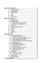
Table of Contents Box Contents ...6 Optional Items...6 GA-EX58-UD5P/GA-EX58-UD5 Motherboard Layout 7 Block Diagram...8 Chapter 1 Hardware Installation 9 1-1 Installation Precautions 9 1-2 Product Specifications 10 1-3 Installing the CPU and CPU Cooler 13 ... Panel Connectors 23 1-9 Onboard LEDs and Switches 25 1-10 Internal Connectors 27 Chapter 2 BIOS Setup 41 2-1 Startup Screen 42 2-2 The Main Menu 43 2-3 MB Intelligent Tweaker(M.I.T 45 2-4 Standard CMOS Features 55 2-5 Advanced BIOS Features 57 2-6 Integrated Peripherals 59 2-7 Power Management Setup 64 2-8 PC Health Status 66...
Table of Contents Box Contents ...6 Optional Items...6 GA-EX58-UD5P/GA-EX58-UD5 Motherboard Layout 7 Block Diagram...8 Chapter 1 Hardware Installation 9 1-1 Installation Precautions 9 1-2 Product Specifications 10 1-3 Installing the CPU and CPU Cooler 13 ... Panel Connectors 23 1-9 Onboard LEDs and Switches 25 1-10 Internal Connectors 27 Chapter 2 BIOS Setup 41 2-1 Startup Screen 42 2-2 The Main Menu 43 2-3 MB Intelligent Tweaker(M.I.T 45 2-4 Standard CMOS Features 55 2-5 Advanced BIOS Features 57 2-6 Integrated Peripherals 59 2-7 Power Management Setup 64 2-8 PC Health Status 66...
Manual
Page 5
...Q-Flash Utility 80 4-2-2 Updating the BIOS with the @BIOS Utility 83 4-3 EasyTune 6...84 4-4 Dynamic Energy Saver Advanced 85 4-5 Ultra TPM* ...87 4-6 Q-Share ...88 4-7 Time Repair ...89 4-8 Teaming ...90 Chapter 5 Appendix ...91 5-1 Configuring SATA Hard Drive(s 91 5-1-1 Configuring Intel ICH10R SATA Controllers 91 5-1-2 Configuring GIGABYTE SATA2/JMB322 SATA Controller 97 5-1-3 ... Sound Recorder 114 5-3 Troubleshooting 115 5-3-1 Frequently Asked Questions 115 5-3-2 Troubleshooting Procedure 116 5-4 POST Error Code 118 5-5 Regulatory Statements 122 "*" Only for GA-EX58-UD5P. - 5 -
...Q-Flash Utility 80 4-2-2 Updating the BIOS with the @BIOS Utility 83 4-3 EasyTune 6...84 4-4 Dynamic Energy Saver Advanced 85 4-5 Ultra TPM* ...87 4-6 Q-Share ...88 4-7 Time Repair ...89 4-8 Teaming ...90 Chapter 5 Appendix ...91 5-1 Configuring SATA Hard Drive(s 91 5-1-1 Configuring Intel ICH10R SATA Controllers 91 5-1-2 Configuring GIGABYTE SATA2/JMB322 SATA Controller 97 5-1-3 ... Sound Recorder 114 5-3 Troubleshooting 115 5-3-1 Frequently Asked Questions 115 5-3-2 Troubleshooting Procedure 116 5-4 POST Error Code 118 5-5 Regulatory Statements 122 "*" Only for GA-EX58-UD5P. - 5 -
Manual
Page 8
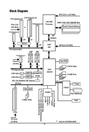
... PCIe CLK (100 MHz) x1 LAN2 LAN1 RJ45 RJ45 RTL RTL 8111D 8111D x1 x1 PCI Express Bus 2 SATA 3Gb/s 2 SATA 3Gb/s JMB322 JMB322 x1 GIGABYTE SATA2 ATA-133/100/66/33 IDE Channel PCI Bus TSB43AB23 QPI Interface Intel® X58 IOH CLK (133 MHz) Intel® ICH10R Dual... BIOS 6 SATA 3Gb/s 12 USB Ports CODEC LPC Bus IT8720 Floppy PS/2 KB/Mouse 3 IEEE 1394a TPM* Surround Speaker Out Center/Subwoofer Speaker Out Side Speaker ...
... PCIe CLK (100 MHz) x1 LAN2 LAN1 RJ45 RJ45 RTL RTL 8111D 8111D x1 x1 PCI Express Bus 2 SATA 3Gb/s 2 SATA 3Gb/s JMB322 JMB322 x1 GIGABYTE SATA2 ATA-133/100/66/33 IDE Channel PCI Bus TSB43AB23 QPI Interface Intel® X58 IOH CLK (133 MHz) Intel® ICH10R Dual... BIOS 6 SATA 3Gb/s 12 USB Ports CODEC LPC Bus IT8720 Floppy PS/2 KB/Mouse 3 IEEE 1394a TPM* Surround Speaker Out Center/Subwoofer Speaker Out Side Speaker ...
Manual
Page 12
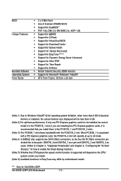
...flash Use of licensed AWARD BIOS Support for DualBIOSTM PnP 1.0a, DMI 2.0, SM BIOS 2.4, ACPI 1.0b Support for @BIOS Support for Q-Flash Support for Virtual Dual BIOS Support for Download Center ...a pair. (Refer to Chapter 2, "Integrated Peripherals" and Chapter 5, "Configuring SA TA Hard Drive(s)," for GA-EX58-UD5P. When PCIEX8_1 is recommended that you install them in the PCIEX16_1 and PCIEX16_2 slots. (Note 3) The PCIEX8_1...to install it is populated with the PCIEX16_2 slot. GA-EX58-UD5P/UD5 Motherboard - 12 -
...flash Use of licensed AWARD BIOS Support for DualBIOSTM PnP 1.0a, DMI 2.0, SM BIOS 2.4, ACPI 1.0b Support for @BIOS Support for Q-Flash Support for Virtual Dual BIOS Support for Download Center ...a pair. (Refer to Chapter 2, "Integrated Peripherals" and Chapter 5, "Configuring SA TA Hard Drive(s)," for GA-EX58-UD5P. When PCIEX8_1 is recommended that you install them in the PCIEX16_1 and PCIEX16_2 slots. (Note 3) The PCIEX8_1...to install it is populated with the PCIEX16_2 slot. GA-EX58-UD5P/UD5 Motherboard - 12 -

Manual
Page 16
...in only one DDR3 memory module is recommended that the motherboard supports the memory. GA-EX58-UD5P/UD5 Motherboard - 16 - When enabling Dual Channel mode with two memory modules, ...be sure to be installed in the DDR3_1 and DDR3_3 sockets. 3 Channel-1. 3 Channel mode cannot be enabled if only one DDR3 memory module is installed, the BIOS... has two memory sockets as following guidelines before installing the memory to GIGABYTE's website for the latest memory support list.) • Always turn ...
...in only one DDR3 memory module is recommended that the motherboard supports the memory. GA-EX58-UD5P/UD5 Motherboard - 16 - When enabling Dual Channel mode with two memory modules, ...be sure to be installed in the DDR3_1 and DDR3_3 sockets. 3 Channel-1. 3 Channel mode cannot be enabled if only one DDR3 memory module is installed, the BIOS... has two memory sockets as following guidelines before installing the memory to GIGABYTE's website for the latest memory support list.) • Always turn ...
Manual
Page 18
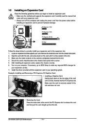
... to install an expansion card: • Make sure the motherboard supports the expansion card. If necessary, go to BIOS Setup to make any required BIOS changes for your expansion card in the slot. 3. GA-EX58-UD5P/UD5 Motherboard - 18 - Remove the metal slot cover from the slot. Secure the card's metal bracket to the chassis...
... to install an expansion card: • Make sure the motherboard supports the expansion card. If necessary, go to BIOS Setup to make any required BIOS changes for your expansion card in the slot. 3. GA-EX58-UD5P/UD5 Motherboard - 18 - Remove the metal slot cover from the slot. Secure the card's metal bracket to the chassis...
Manual
Page 33
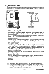
... indicator on the chassis front panel. The system reports system startup status by chassis. When connecting your system using the power switch (refer to Chapter 2, "BIOS Setup," "Power Management Setup," for information about beep codes. • HD (Hard Drive Activity LED, Blue) Connects to indicate the problem. A front ... System Status LED Connects to the pin assignments below. The S0 On LED is operating. The LED is off when the system is detected, the BIOS may issue beeps in S3/S4/S5 Off S3/S4 sleep state or powered off (S5). • PW (Power Switch, Red): Connects to ...
... indicator on the chassis front panel. The system reports system startup status by chassis. When connecting your system using the power switch (refer to Chapter 2, "BIOS Setup," "Power Management Setup," for information about beep codes. • HD (Hard Drive Activity LED, Blue) Connects to indicate the problem. A front ... System Status LED Connects to the pin assignments below. The S0 On LED is operating. The LED is off when the system is detected, the BIOS may issue beeps in S3/S4/S5 Off S3/S4 sleep state or powered off (S5). • PW (Power Switch, Red): Connects to ...
Manual
Page 37
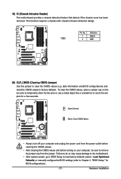
... pins to temporarily short the two pins or use a metal object like a screwdriver to touch the two pins for BIOS configurations). - 37 - date information and BIOS configurations) and reset the CMOS values to Chapter 2, "BIOS Setup," for a few seconds. This function requires a chassis with chassis intrusion detection design. To clear the CMOS values... computer and unplug the power cord from the jumper. Failure to do so may cause damage to the motherboard. • After system restart, go to BIOS Setup to load factory defaults (select Load Optimized Defaults) or manually configure the...
... pins to temporarily short the two pins or use a metal object like a screwdriver to touch the two pins for BIOS configurations). - 37 - date information and BIOS configurations) and reset the CMOS values to Chapter 2, "BIOS Setup," for a few seconds. This function requires a chassis with chassis intrusion detection design. To clear the CMOS values... computer and unplug the power cord from the jumper. Failure to do so may cause damage to the motherboard. • After system restart, go to BIOS Setup to load factory defaults (select Load Optimized Defaults) or manually configure the...
Manual
Page 38
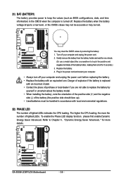
... the more details. Turn off your computer and unplug the power cord. 2. Gently remove the battery from the battery holder and wait for one . GA-EX58-UD5P/UD5 Motherboard - 38 - Refer to Chapter 4, "Dynamic Energy Saver Advanced, " for 5 seconds.) 3. To enable the Phase LED display function, please ...up). • Used batteries must be lost. 21) BAT (BATTERY) The battery provides power to keep the values (such as BIOS configurations, date, and time information) in accordance with local environmental regulations. 22) PHASE LED The number of lighted LEDs indicates the CPU loading....
... the more details. Turn off your computer and unplug the power cord. 2. Gently remove the battery from the battery holder and wait for one . GA-EX58-UD5P/UD5 Motherboard - 38 - Refer to Chapter 4, "Dynamic Energy Saver Advanced, " for 5 seconds.) 3. To enable the Phase LED display function, please ...up). • Used batteries must be lost. 21) BAT (BATTERY) The battery provides power to keep the values (such as BIOS configurations, date, and time information) in accordance with local environmental regulations. 22) PHASE LED The number of lighted LEDs indicates the CPU loading....

Manual
Page 41
... and loading operating system, etc. To upgrade the BIOS, use either the GIGABYTE Q-Flash or @BIOS utility . • Q-Flash allows the user to Chapter 4, "BIOS Update Utilities." • Because BIOS flashing is recommended that searches and downloads the latest version of BIOS from the Internet and updates the BIOS. For instructions on using the current version of...
... and loading operating system, etc. To upgrade the BIOS, use either the GIGABYTE Q-Flash or @BIOS utility . • Q-Flash allows the user to Chapter 4, "BIOS Update Utilities." • Because BIOS flashing is recommended that searches and downloads the latest version of BIOS from the Internet and updates the BIOS. For instructions on using the current version of...
Manual
Page 42
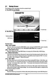
... boot from the device configured in Boot Menu. GA-EX58-UD5P/UD5 Motherboard - 42 - To exit Boot Menu, press . A. For more information, refer to Chapter 4, "Xpress Recovery2." : BOOT MENU Boot Menu allows you have ever entered Xpress Recovery2 to enter BIOS Setup first. To show the BIOS POST screen. You can be based on page...
... boot from the device configured in Boot Menu. GA-EX58-UD5P/UD5 Motherboard - 42 - To exit Boot Menu, press . A. For more information, refer to Chapter 4, "Xpress Recovery2." : BOOT MENU Boot Menu allows you have ever entered Xpress Recovery2 to enter BIOS Setup first. To show the BIOS POST screen. You can be based on page...
Manual
Page 43
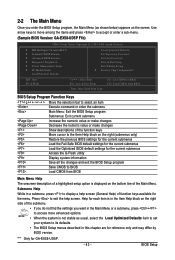
...of the Main Menu. Use arrow keys to move among the items and press to accept or enter a sub-menu. (Sample BIOS Version: GA-EX58-UD5P F1b) ) CMOS Setup Utility-Copyright (C) 1984-2008 Award Software MB Intelligent Tweaker(M.I.T.) Standard CMOS Features Advanced... Quit F8: Q-Flash Select Item F10: Save & Exit Setup F11: Save CMOS to BIOS F12: Load CMOS from BIOS Main Menu Help The onscreen description of function keys available for GA-EX58-UD5P. - 43 - BIOS Setup Program Function Keys Move the selection bar to select an item Execute command or enter ...
...of the Main Menu. Use arrow keys to move among the items and press to accept or enter a sub-menu. (Sample BIOS Version: GA-EX58-UD5P F1b) ) CMOS Setup Utility-Copyright (C) 1984-2008 Award Software MB Intelligent Tweaker(M.I.T.) Standard CMOS Features Advanced... Quit F8: Q-Flash Select Item F10: Save & Exit Setup F11: Save CMOS to BIOS F12: Load CMOS from BIOS Main Menu Help The onscreen description of function keys available for GA-EX58-UD5P. - 43 - BIOS Setup Program Function Keys Move the selection bar to select an item Execute command or enter ...

Manual
Page 44
... can use the SPACE key) and then press to complete. F12 : Load CMOS from a profile created before, without the hassles of reconfiguring the BIOS settings. GA-EX58-UD5P/UD5 Motherboard - 44 - First select the profile you can create up to 8 profiles (Profile 1-8) and name each profile. The Functions of the and keys...
... can use the SPACE key) and then press to complete. F12 : Load CMOS from a profile created before, without the hassles of reconfiguring the BIOS settings. GA-EX58-UD5P/UD5 Motherboard - 44 - First select the profile you can create up to 8 profiles (Profile 1-8) and name each profile. The Functions of the and keys...
Manual
Page 45
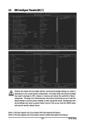
... stably with the overclock/overvoltage settings you made is for advanced users only and we recommend you install a memory module that supports this feature. - 45 - BIOS Setup If this occurs, clear the CMOS values and reset the board to CPU, chipset, or memory and reduce the useful life of these components...
... stably with the overclock/overvoltage settings you made is for advanced users only and we recommend you install a memory module that supports this feature. - 45 - BIOS Setup If this occurs, clear the CMOS values and reset the board to CPU, chipset, or memory and reduce the useful life of these components...
Manual
Page 47
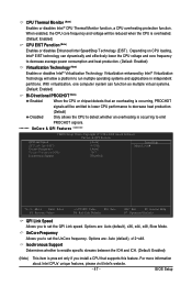
UnCore Frequency Allows you to set the UnCore frequency. BIOS Setup Virtualization enhanced by Intel® Virtualization Technology will be reduced when the CPU is present only if you install a CPU that an overheating is ...
UnCore Frequency Allows you to set the UnCore frequency. BIOS Setup Virtualization enhanced by Intel® Virtualization Technology will be reduced when the CPU is present only if you install a CPU that an overheating is ...

Manual
Page 49
Standard Lets the system operate at its basic performance level. BIOS Setup Options are : 700mV, 800mV, 900mV (default), 1000mV. Options are : 0ps~750ps. (Default: 0ps) ******* Advanced DRAM Features******* CMOS Setup Utility-Copyright (C) 1984-2008 Award Software ... adjust the amplitude of the CPU and North Bridge clock. CPU Clock Skew Allows you to the CPU clock. Extreme Memory Profile (X.M.P.) (Note) Allows the BIOS to read the SPD data on XMP memory module(s) to adjust the amplitude of the PCI Express and North Bridge clock. Options are : 0ps~750ps...
Standard Lets the system operate at its basic performance level. BIOS Setup Options are : 700mV, 800mV, 900mV (default), 1000mV. Options are : 0ps~750ps. (Default: 0ps) ******* Advanced DRAM Features******* CMOS Setup Utility-Copyright (C) 1984-2008 Award Software ... adjust the amplitude of the CPU and North Bridge clock. CPU Clock Skew Allows you to the CPU clock. Extreme Memory Profile (X.M.P.) (Note) Allows the BIOS to read the SPD data on XMP memory module(s) to adjust the amplitude of the PCI Express and North Bridge clock. Options are : 0ps~750ps...
Manual
Page 51
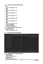
... Options are : Auto (default), 1~15. tRRD Options are : Auto (default), 1~8. - 51 - tRTP Options are : Auto (default), 1~63. ESC: Exit F1: General Help F7: Optimized Defaults BIOS Setup >>>>> Channel A/B/C Advanced Timing Control tRC Options are : Auto (default), 1~15. tWTR Options are : Auto (default), 1~31. tWR Options are : Auto (default), 1~31. tFAW Options...
... Options are : Auto (default), 1~15. tRRD Options are : Auto (default), 1~8. - 51 - tRTP Options are : Auto (default), 1~63. ESC: Exit F1: General Help F7: Optimized Defaults BIOS Setup >>>>> Channel A/B/C Advanced Timing Control tRC Options are : Auto (default), 1~15. tWTR Options are : Auto (default), 1~31. tWR Options are : Auto (default), 1~31. tFAW Options...

Manual
Page 53
...-Line Calibration Enables or disables Load-Line Calibration. Disabled sets the CPU voltage following Intel specifications. (Default: Disabled) CPU Vcore The default is Auto. - 53 - BIOS Setup Ch-B Address VRef. ******* Advanced Voltage Control******* CMOS Setup Utility-Copyright (C) 1984-2008 Award Software Advanced Voltage Control Voltage Types Normal Current >>> CPU Load-Line...
...-Line Calibration Enables or disables Load-Line Calibration. Disabled sets the CPU voltage following Intel specifications. (Default: Disabled) CPU Vcore The default is Auto. - 53 - BIOS Setup Ch-B Address VRef. ******* Advanced Voltage Control******* CMOS Setup Utility-Copyright (C) 1984-2008 Award Software Advanced Voltage Control Voltage Types Normal Current >>> CPU Load-Line...
Manual
Page 55
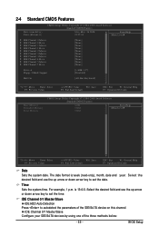
... the IDE/SA TA device on this channel. Select the desired field and use the up arrow or down arrow key to set the date. BIOS Setup 2-4 Standard CMOS Features Date (mm:dd:yy) Time (hh:mm:ss) CMOS Setup Utility-Copyright (C) 1984-2008 Award Software Standard CMOS Features Mon, May...
... the IDE/SA TA device on this channel. Select the desired field and use the up arrow or down arrow key to set the date. BIOS Setup 2-4 Standard CMOS Features Date (mm:dd:yy) Time (hh:mm:ss) CMOS Setup Utility-Copyright (C) 1984-2008 Award Software Standard CMOS Features Mon, May...


