Manual
Page 3
...or published in this : "REV: X.X." Disclaimer Information in the use GIGABYTE's unique features, read the User's Manual. For instructions on your motherboard revision before updating motherboard BIOS, drivers, or when looking for technical information. Documentation Classifications In order... to assist in this product, GIGABYTE provides the following types of documentations: For quick set...
...or published in this : "REV: X.X." Disclaimer Information in the use GIGABYTE's unique features, read the User's Manual. For instructions on your motherboard revision before updating motherboard BIOS, drivers, or when looking for technical information. Documentation Classifications In order... to assist in this product, GIGABYTE provides the following types of documentations: For quick set...

Manual
Page 4
Table of Contents Box Contents ...6 OptionalItems ...6 GA-EX58-DS4 Motherboard Layout 7 Block Diagram ...8 Chapter 1 Hardware Installation 9 1-1 Installation Precautions 9 1-2 Product Specifications 10 1-3 Installing the CPU and CPU Cooler ... Installing an Expansion Card 18 1-6 Back Panel Connectors 19 1-7 Internal Connectors 21 Chapter 2 BIOS Setup 35 2-1 Startup Screen 36 2-2 The Main Menu 37 2-3 MB Intelligent Tweaker(M.I.T 39 2-4 Standard CMOS Features 49 2-5 Advanced BIOS Features 51 2-6 IntegratedPeripherals 53 2-7 Power Management Setup 56 2-8 PC Health Status 58 2-9 Load...
Table of Contents Box Contents ...6 OptionalItems ...6 GA-EX58-DS4 Motherboard Layout 7 Block Diagram ...8 Chapter 1 Hardware Installation 9 1-1 Installation Precautions 9 1-2 Product Specifications 10 1-3 Installing the CPU and CPU Cooler ... Installing an Expansion Card 18 1-6 Back Panel Connectors 19 1-7 Internal Connectors 21 Chapter 2 BIOS Setup 35 2-1 Startup Screen 36 2-2 The Main Menu 37 2-3 MB Intelligent Tweaker(M.I.T 39 2-4 Standard CMOS Features 49 2-5 Advanced BIOS Features 51 2-6 IntegratedPeripherals 53 2-7 Power Management Setup 56 2-8 PC Health Status 58 2-9 Load...
Manual
Page 5
... Download Center 66 Chapter 4 Unique Features 67 4-1 Xpress Recovery2 67 4-2 BIOS Update Utilities 70 4-2-1 Updating the BIOS with the Q-Flash Utility 70 4-2-2 Updating the BIOS with the @BIOS Utility 73 4-3 EasyTune 6 ...74 4-4 Dynamic Energy Saver Advanced 75 4-5 ...Q-Share ...77 4-6 Time Repair ...78 Chapter 5 Appendix ...79 5-1 Configuring SATA Hard Drive(s 79 5-1-1 Configuring Intel ICH10R SATA Controllers 79 5-1-2 Configuring GIGABYTE...
... Download Center 66 Chapter 4 Unique Features 67 4-1 Xpress Recovery2 67 4-2 BIOS Update Utilities 70 4-2-1 Updating the BIOS with the Q-Flash Utility 70 4-2-2 Updating the BIOS with the @BIOS Utility 73 4-3 EasyTune 6 ...74 4-4 Dynamic Energy Saver Advanced 75 4-5 ...Q-Share ...77 4-6 Time Repair ...78 Chapter 5 Appendix ...79 5-1 Configuring SATA Hard Drive(s 79 5-1-1 Configuring Intel ICH10R SATA Controllers 79 5-1-2 Configuring GIGABYTE...
Manual
Page 8
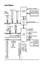
... 8111D x1 PCI Express Bus 2 SATA 3Gb/s ATA-133/100/66/33 IDE Channel PCI Bus x1 GIGABYTE SATA2 TSB43AB23 3 IEEE 1394a Intel® X58 Intel® ICH10R CODEC IOH CLK (133 MHz) Dual BIOS 6 SATA 3Gb/s 12 USB Ports LPC Bus IT8720 Floppy COM Port PS/2 KB/Mouse Surround Speaker Out...
... 8111D x1 PCI Express Bus 2 SATA 3Gb/s ATA-133/100/66/33 IDE Channel PCI Bus x1 GIGABYTE SATA2 TSB43AB23 3 IEEE 1394a Intel® X58 Intel® ICH10R CODEC IOH CLK (133 MHz) Dual BIOS 6 SATA 3Gb/s 12 USB Ports LPC Bus IT8720 Floppy COM Port PS/2 KB/Mouse Surround Speaker Out...

Manual
Page 12
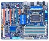
GA-EX58-DS4 Motherboard - 12 - if you are installing two PCI Express graphics cards, it is recommended that you install them in the PCIEX16_1 and PCIEX8_1 slots. (Note 3) ... Software Operating System Form Factor 2 x 8 Mbit flash Use of licensed AWARD BIOS Support for DualBIOSTM PnP 1.0a, DMI 2.0, SM BIOS 2.4, ACPI 1.0b Support for @BIOS Support for Q-Flash Support for Virtual Dual BIOS Support for Download Center Support for Xpress Install Support for Xpress...
GA-EX58-DS4 Motherboard - 12 - if you are installing two PCI Express graphics cards, it is recommended that you install them in the PCIEX16_1 and PCIEX8_1 slots. (Note 3) ... Software Operating System Form Factor 2 x 8 Mbit flash Use of licensed AWARD BIOS Support for DualBIOSTM PnP 1.0a, DMI 2.0, SM BIOS 2.4, ACPI 1.0b Support for @BIOS Support for Q-Flash Support for Virtual Dual BIOS Support for Download Center Support for Xpress Install Support for Xpress...
Manual
Page 16
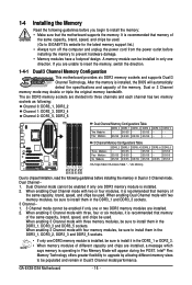
It is installed, the BIOS will appear during the POST. Dual or 3 Channel memory mode may double or triple the original memory...Four Modules Six Modules DDR3_2 - Intel® Flex Memory Technology offers greater flexibility to upgrade by allowing different memory sizes to GIGABYTE's website for the latest memory support list.) • Always turn off the computer and unplug the power cord from the ... Channel 0: DDR3_1, DDR3_2 Channel 1: DDR3_3, DDR3_4 Channel 2: DDR3_5, DDR3_6 Dual Channel Memory Configurations Table Two Modules Four Modules DDR3_2 - GA-EX58-DS4 Motherboard - 16 -
It is installed, the BIOS will appear during the POST. Dual or 3 Channel memory mode may double or triple the original memory...Four Modules Six Modules DDR3_2 - Intel® Flex Memory Technology offers greater flexibility to upgrade by allowing different memory sizes to GIGABYTE's website for the latest memory support list.) • Always turn off the computer and unplug the power cord from the ... Channel 0: DDR3_1, DDR3_2 Channel 1: DDR3_3, DDR3_4 Channel 2: DDR3_5, DDR3_6 Dual Channel Memory Configurations Table Two Modules Four Modules DDR3_2 - GA-EX58-DS4 Motherboard - 16 -
Manual
Page 18
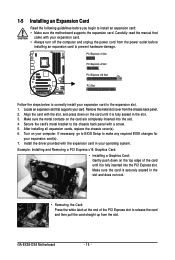
..., replace the chassis cover(s). 6. Turn on the card until it is fully inserted into the slot. 4. If necessary, go to BIOS Setup to make any required BIOS changes for your operating system. GA-EX58-DS4 Motherboard - 18 - PCI Express x1 Slot PCI Express x4 Slot PCI Express x16 Slot PCI Slot Follow the steps below...
..., replace the chassis cover(s). 6. Turn on the card until it is fully inserted into the slot. 4. If necessary, go to BIOS Setup to make any required BIOS changes for your operating system. GA-EX58-DS4 Motherboard - 18 - PCI Express x1 Slot PCI Express x4 Slot PCI Express x16 Slot PCI Slot Follow the steps below...
Manual
Page 26
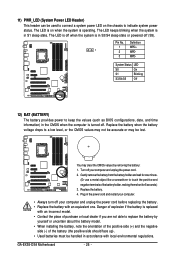
... System Status LED S0 On S1 Blinking S3/S4/S5 Off 12) BAT (BATTERY) The battery provides power to keep the values (such as BIOS configurations, date, and time information) in the CMOS when the computer is replaced with an incorrect model. • Contact the place of purchase ...state or powered off your computer and unplug the power cord before replacing the battery. • Replace the battery with local environmental regulations. Pin No. GA-EX58-DS4 Motherboard - 26 - 11) PWR_LED (System Power LED Header) This header can be used to connect a system power LED on when the system is...
... System Status LED S0 On S1 Blinking S3/S4/S5 Off 12) BAT (BATTERY) The battery provides power to keep the values (such as BIOS configurations, date, and time information) in the CMOS when the computer is replaced with an incorrect model. • Contact the place of purchase ...state or powered off your computer and unplug the power cord before replacing the battery. • Replace the battery with local environmental regulations. Pin No. GA-EX58-DS4 Motherboard - 26 - 11) PWR_LED (System Power LED Header) This header can be used to connect a system power LED on when the system is...
Manual
Page 27
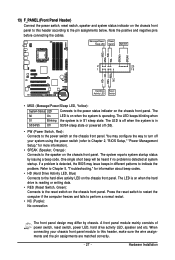
...of power switch, reset switch, power LED, hard drive activity LED, speaker and etc. When connecting your system using the power switch (refer to Chapter 2, "BIOS Setup," "Power Management Setup," for information about beep codes. • HD (Hard Drive Activity LED, Blue) Connects to the speaker on the chassis front ..., Yellow): System Status LED Connects to the reset switch on the chassis front panel. The LED is on when the hard drive is detected, the BIOS may differ by issuing a beep code. The LED is off (S5). • PW (Power Switch, Red): Connects to the power switch on the ...
...of power switch, reset switch, power LED, hard drive activity LED, speaker and etc. When connecting your system using the power switch (refer to Chapter 2, "BIOS Setup," "Power Management Setup," for information about beep codes. • HD (Hard Drive Activity LED, Blue) Connects to the speaker on the chassis front ..., Yellow): System Status LED Connects to the reset switch on the chassis front panel. The LED is on when the hard drive is detected, the BIOS may differ by issuing a beep code. The LED is off (S5). • PW (Power Switch, Red): Connects to the power switch on the ...

Manual
Page 32
... do so may cause damage to the motherboard. • After system restart, go to BIOS Setup to load factory defaults (select Load Optimized Defaults) or manually configure the BIOS settings (refer to touch the two pins for a few seconds. GA-EX58-DS4 Motherboard - 32 - To clear the CMOS values, place a jumper cap on your computer...
... do so may cause damage to the motherboard. • After system restart, go to BIOS Setup to load factory defaults (select Load Optimized Defaults) or manually configure the BIOS settings (refer to touch the two pins for a few seconds. GA-EX58-DS4 Motherboard - 32 - To clear the CMOS values, place a jumper cap on your computer...
Manual
Page 35
...instability or other unexpected results. When the power is recommended that searches and downloads the latest version of BIOS from the Internet and updates the BIOS. For instructions on the motherboard. Inadequate BIOS flashing may result in Chapter 1 for the beep codes description. • It is turned on ... Its major functions include conducting the Power-On Self-Test (POST) during the POST. To upgrade the BIOS, use either the GIGABYTE Q-Flash or @BIOS utility. • Q-Flash allows the user to activate certain system features. If this occurs, try to clear the CMOS values ...
...instability or other unexpected results. When the power is recommended that searches and downloads the latest version of BIOS from the Internet and updates the BIOS. For instructions on the motherboard. Inadequate BIOS flashing may result in Chapter 1 for the beep codes description. • It is turned on ... Its major functions include conducting the Power-On Self-Test (POST) during the POST. To upgrade the BIOS, use either the GIGABYTE Q-Flash or @BIOS utility. • Q-Flash allows the user to activate certain system features. If this occurs, try to clear the CMOS values ...
Manual
Page 36
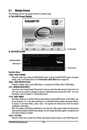
... system startup, refer to the instructions on the Full Screen LOGO Show item on BIOS Setup settings. A. The LOGO Screen (Default) B. To show the BIOS POST screen. 2-1 Startup Screen The following screens may appear when the computer boots. EX58-DS4 F2a . . . . : BIOS Setup : XpressRecovery2 : Boot Menu : Qflash 11/03/2008-X58-ICH10-7A89QG01C-00 Function... have ever entered Xpress Recovery2 to back up arrow key < > or the down arrow key< > to select the first boot device, then press to enter BIOS Setup first. To exit Boot Menu, press . GA-EX58-DS4 Motherboard - 36 -
... system startup, refer to the instructions on the Full Screen LOGO Show item on BIOS Setup settings. A. The LOGO Screen (Default) B. To show the BIOS POST screen. 2-1 Startup Screen The following screens may appear when the computer boots. EX58-DS4 F2a . . . . : BIOS Setup : XpressRecovery2 : Boot Menu : Qflash 11/03/2008-X58-ICH10-7A89QG01C-00 Function... have ever entered Xpress Recovery2 to back up arrow key < > or the down arrow key< > to select the first boot device, then press to enter BIOS Setup first. To exit Boot Menu, press . GA-EX58-DS4 Motherboard - 36 -
Manual
Page 37
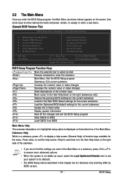
...Exit Setup Exit Without Saving ESC: Quit F8: Q-Flash Select Item F10: Save & Exit Setup F11: Save CMOS to BIOS F12: Load CMOS from BIOS Change CPU's Clock & Voltage BIOS Setup Program Function Keys Move the selection bar to select an item Execute command or enter the submenu Main Menu: Exit... the BIOS Setup program Submenus: Exit current submenu Increase the numeric value or make changes Decrease the numeric value or make changes Show descriptions...
...Exit Setup Exit Without Saving ESC: Quit F8: Q-Flash Select Item F10: Save & Exit Setup F11: Save CMOS to BIOS F12: Load CMOS from BIOS Change CPU's Clock & Voltage BIOS Setup Program Function Keys Move the selection bar to select an item Execute command or enter the submenu Main Menu: Exit... the BIOS Setup program Submenus: Exit current submenu Increase the numeric value or make changes Decrease the numeric value or make changes Show descriptions...
Manual
Page 38
...password. You can create up to the confirmation message will exit BIOS Setup. (Pressing can also carry out this task.) GA-EX58-DS4 Motherboard - 38 - An user password only allows you to save the current BIOS settings to load the BIOS settings from BIOS If your CPU, memory, etc. Standard CMOS ... and date, hard drive types, floppy disk drive types, and the type of errors that stop the system boot, etc. Advanced BIOS Features Use this menu to configure the device boot order, advanced features available on the CPU, and the primary display adapter. Integrated...
...password. You can create up to the confirmation message will exit BIOS Setup. (Pressing can also carry out this task.) GA-EX58-DS4 Motherboard - 38 - An user password only allows you to save the current BIOS settings to load the BIOS settings from BIOS If your CPU, memory, etc. Standard CMOS ... and date, hard drive types, floppy disk drive types, and the type of errors that stop the system boot, etc. Advanced BIOS Features Use this menu to configure the device boot order, advanced features available on the CPU, and the primary display adapter. Integrated...
Manual
Page 39
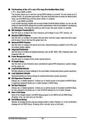
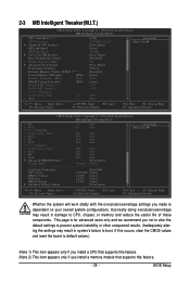
... system's failure to CPU, chipset, or memory and reduce the useful life of these components. Incorrectly doing overclock/overvoltage may result in damage to boot. BIOS Setup 2-3 MB Intelligent Tweaker(M.I.T.) CMOS Setup Utility-Copyright (C) 1984-2008 Award Software MB Intelligent Tweaker(M.I.T.) CPU Clock Ratio (Note 1) CPU Frequency Advanced CPU Features...
... system's failure to CPU, chipset, or memory and reduce the useful life of these components. Incorrectly doing overclock/overvoltage may result in damage to boot. BIOS Setup 2-3 MB Intelligent Tweaker(M.I.T.) CMOS Setup Utility-Copyright (C) 1984-2008 Award Software MB Intelligent Tweaker(M.I.T.) CPU Clock Ratio (Note 1) CPU Frequency Advanced CPU Features...
Manual
Page 41
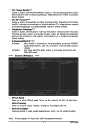
... overheated. (Default: Enabled) CPU EIST Function (Note) Enables or disables Enhanced Intel SpeedStep Technology (EIST). UnCore Frequency Allows you to set the QPI Link speed. BIOS Setup With virtualization, one computer system can dynamically and effectively lower the CPU voltage and core frequency to decrease average power consumption and heat production...
... overheated. (Default: Enabled) CPU EIST Function (Note) Enables or disables Enhanced Intel SpeedStep Technology (EIST). UnCore Frequency Allows you to set the QPI Link speed. BIOS Setup With virtualization, one computer system can dynamically and effectively lower the CPU voltage and core frequency to decrease average power consumption and heat production...
Manual
Page 43
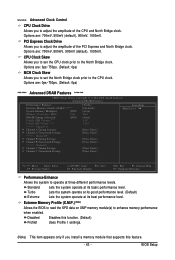
Standard Lets the system operate at its basic performance level. Extreme Memory Profile (X.M.P.) (Note) Allows the BIOS to read the SPD data on XMP memory module(s) to operate at three different performance levels. PCI Express Clock Drive Allows... to the CPU clock. Turbo Lets the system operate at its good performance level. (Default) Extreme Lets the system operate at its best performance level. BIOS Setup Options are : 700mV, 800mV, 900mV (default), 1000mV. Disabled Profile1 Disables this feature. - 43 - Options are : 0ps~750ps. (Default: 0ps) ******* Advanced ...
Standard Lets the system operate at its basic performance level. Extreme Memory Profile (X.M.P.) (Note) Allows the BIOS to read the SPD data on XMP memory module(s) to operate at three different performance levels. PCI Express Clock Drive Allows... to the CPU clock. Turbo Lets the system operate at its good performance level. (Default) Extreme Lets the system operate at its best performance level. BIOS Setup Options are : 700mV, 800mV, 900mV (default), 1000mV. Disabled Profile1 Disables this feature. - 43 - Options are : 0ps~750ps. (Default: 0ps) ******* Advanced ...
Manual
Page 45
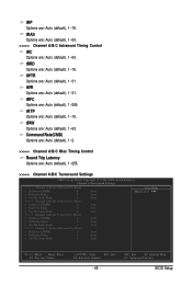
...(CMD) Options are: Auto (default), 1~2. >>>>> Channel A/B/C Misc Timing Control Round Trip Latency Options are : Auto (default), 1~255. ESC: Exit F1: General Help F7: Optimized Defaults BIOS Setup tRFC Options are : Auto (default), 1~255. >>>>> Channel A/B/C Turnaround Settings CMOS Setup Utility-Copyright (C) 1984-2008 Award Software Channel A Turnaround Settings >>>>> Channel A Writes Followed by...
...(CMD) Options are: Auto (default), 1~2. >>>>> Channel A/B/C Misc Timing Control Round Trip Latency Options are : Auto (default), 1~255. ESC: Exit F1: General Help F7: Optimized Defaults BIOS Setup tRFC Options are : Auto (default), 1~255. >>>>> Channel A/B/C Turnaround Settings CMOS Setup Utility-Copyright (C) 1984-2008 Award Software Channel A Turnaround Settings >>>>> Channel A Writes Followed by...
Manual
Page 47
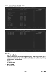
... ESC: Exit F1: General Help F7: Optimized Defaults >>> CPU Load-Line Calibration Enables or disables Load-Line Calibration. QPI/Vtt Voltage The default is Auto. BIOS Setup Ch-B Address VRef. Disabled sets the CPU voltage following Intel specifications. (Default: Disabled) CPU Vcore The default is Auto. - 47 - Enabling this feature adjusts...
... ESC: Exit F1: General Help F7: Optimized Defaults >>> CPU Load-Line Calibration Enables or disables Load-Line Calibration. QPI/Vtt Voltage The default is Auto. BIOS Setup Ch-B Address VRef. Disabled sets the CPU voltage following Intel specifications. (Default: Disabled) CPU Vcore The default is Auto. - 47 - Enabling this feature adjusts...
Manual
Page 49
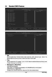
... field and use the up arrow or down arrow key to autodetect the parameters of the three methods below: - 49 - Time Sets the system time. BIOS Setup IDE Channel 0, 1 Master/Slave IDE HDD Auto-Detection Press to set the time. Select the desired field and use the up arrow or down...
... field and use the up arrow or down arrow key to autodetect the parameters of the three methods below: - 49 - Time Sets the system time. BIOS Setup IDE Channel 0, 1 Master/Slave IDE HDD Auto-Detection Press to set the time. Select the desired field and use the up arrow or down...


