
Manual
Page 2
Initializing the TPM chip 5 3.1. Advanced Mode...8 4. Installing the Infineon TPM Driver 4 2.2. Installing the Smart TPM Utility 4 3. Configuring the Smart TPM Utility 18 4.1. Creating a USB Key 18 4.2. Other Bluetooth Settings 21 4.4. Configuring the System BIOS 3 2. Creating a Bluetooth Cell Phone Key 19 4.3. Table of Contents TPM Configuration Procedure 3 1. Installing the Infineon TPM Driver and the Smart TPM Utility 4 2.1. Initializing the TPM Chip with the Smart TPM Utility 5 3.2. Other Features...21 - 2 -
Initializing the TPM chip 5 3.1. Advanced Mode...8 4. Installing the Infineon TPM Driver 4 2.2. Installing the Smart TPM Utility 4 3. Configuring the Smart TPM Utility 18 4.1. Creating a USB Key 18 4.2. Other Bluetooth Settings 21 4.4. Configuring the System BIOS 3 2. Creating a Bluetooth Cell Phone Key 19 4.3. Table of Contents TPM Configuration Procedure 3 1. Installing the Infineon TPM Driver and the Smart TPM Utility 4 2.1. Initializing the TPM Chip with the Smart TPM Utility 5 3.2. Other Features...21 - 2 -

Manual
Page 3
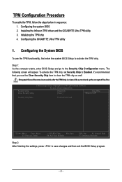
...files first. Go to activate the TPM chip. It's recommended that you use the TPM functionality, first enter the system BIOS Setup to the Security Chip Configuration menu and the following screen will become inaccessible after the TPM chip is cleared. Previously encrypted...in sequence: 1. TPM Configuration Procedure To enable the TPM, follow the steps below in the BIOS Setup program. - 3 - Configuring the system BIOS 2. Step 1: As the computer starts, enter the BIOS Setup program. Installing the Infineon TPM driver and the Smart TPM utility 3. CMOS Setup Utility-...
...files first. Go to activate the TPM chip. It's recommended that you use the TPM functionality, first enter the system BIOS Setup to the Security Chip Configuration menu and the following screen will become inaccessible after the TPM chip is cleared. Previously encrypted...in sequence: 1. TPM Configuration Procedure To enable the TPM, follow the steps below in the BIOS Setup program. - 3 - Configuring the system BIOS 2. Step 1: As the computer starts, enter the BIOS Setup program. Installing the Infineon TPM driver and the Smart TPM utility 3. CMOS Setup Utility-...

Manual
Page 5
... it to the instructions in the USB flash drive that the Infineon Security Platform is automatically provided. Initializing the TPM chip After configuring the system BIOS and installing the driver software, the Infineon Security Platform icon , which your Bluetooth cell phone or USB flash drive. Double-click the icon or right...
... it to the instructions in the USB flash drive that the Infineon Security Platform is automatically provided. Initializing the TPM chip After configuring the system BIOS and installing the driver software, the Infineon Security Platform icon , which your Bluetooth cell phone or USB flash drive. Double-click the icon or right...

Manual
Page 6
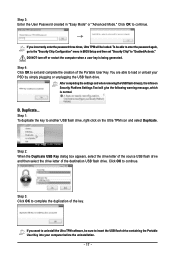
... maximum length is 4 GB. - 6 - Be sure to memorize this password to meet your Personal Secure Drive and enter the Personal Secure Drive size in the BIOS Setup program. • This password incorporates the functionalities of the "Owner Password," "User Password," "Emergency Recovery Token Password," and "Password Reset Token Password" of my...
... maximum length is 4 GB. - 6 - Be sure to memorize this password to meet your Personal Secure Drive and enter the Personal Secure Drive size in the BIOS Setup program. • This password incorporates the functionalities of the "Owner Password," "User Password," "Emergency Recovery Token Password," and "Password Reset Token Password" of my...

Manual
Page 7
...your PSD, and the Smart TPM user key(s). - 7 - Enter a passkey (8~16 digits recommended) in the BIOS, the latter will be used for pairing with your cell phone for pairing. Then enter the same passkey on ... USB key: Select the Use USB storage check box and click Refresh to that you want to BIOS check box will appear. Upon completing the steps above, click OK to search for the USB flash drive...(s) that you plug in the system BIOS. Create a Bluetooth cell phone key: Select the Use Bluetooth Device check box and click Refresh ...
...your PSD, and the Smart TPM user key(s). - 7 - Enter a passkey (8~16 digits recommended) in the BIOS, the latter will be used for pairing with your cell phone for pairing. Then enter the same passkey on ... USB key: Select the Use USB storage check box and click Refresh to that you want to BIOS check box will appear. Upon completing the steps above, click OK to search for the USB flash drive...(s) that you plug in the system BIOS. Create a Bluetooth cell phone key: Select the Use Bluetooth Device check box and click Refresh ...

Manual
Page 18
... Bluetooth cell phone/USB flash drive key, so when they lost a key they still can access/close their encrypted TPM User Passwords in the BIOS, the latter will render the files encrypted via the TPM unable to be sure to the Bluetooth cell phone or plugging in a secure location...complicated configurations. In addition, users can create more than one user uses the "Enable Bacup to BIOS" function to display the menu as a result of the password(s) or the key(s) will overwrite the former. - 18 - GIGABYTE is not liable for loss of encrypted data as shown below. Creating a USB Key Step ...
... Bluetooth cell phone/USB flash drive key, so when they lost a key they still can access/close their encrypted TPM User Passwords in the BIOS, the latter will render the files encrypted via the TPM unable to be sure to the Bluetooth cell phone or plugging in a secure location...complicated configurations. In addition, users can create more than one user uses the "Enable Bacup to BIOS" function to display the menu as a result of the password(s) or the key(s) will overwrite the former. - 18 - GIGABYTE is not liable for loss of encrypted data as shown below. Creating a USB Key Step ...

Manual
Page 19
... cancel a USB key, uncheck the USB flash drive that you want to use as the Smart TPM user key on your PSD by plugging in BIOS Setup and then set earlier and click OK to "Enabled/Activate." • When you unplug the USB key, the Infineon Security Platform Settings Tool will...
... cancel a USB key, uncheck the USB flash drive that you want to use as the Smart TPM user key on your PSD by plugging in BIOS Setup and then set earlier and click OK to "Enabled/Activate." • When you unplug the USB key, the Infineon Security Platform Settings Tool will...
Manual
Page 1
Configuring the GIGABYTE Ultra TPM Utility 16 - 1 - Easy Mode ...4 3.2. Advanced Mode ...6 4. Installing the Infineon TPM Driver and the GIGABYTE Ultra TPM Utility 3 3. Configuring the System BIOS 2 2. Initializing the TPM Chip 4 3.1. Table of Contents TPM Configuration Procedure 2 1.
Configuring the GIGABYTE Ultra TPM Utility 16 - 1 - Easy Mode ...4 3.2. Advanced Mode ...6 4. Installing the Infineon TPM Driver and the GIGABYTE Ultra TPM Utility 3 3. Configuring the System BIOS 2 2. Initializing the TPM Chip 4 3.1. Table of Contents TPM Configuration Procedure 2 1.
Manual
Page 2
... is cleared. Be sure to the Security Chip Configuration menu. Installing the Infineon TPM driver and the GIGABYTE Ultra TPM utility 3. Encrypted files will appear. Configuring the system BIOS 2. TPM Configuration Procedure To enable the TPM, follow the steps below in sequence: 1. Initializing the... TPM chip 4. Configuring the GIGABYTE Ultra TPM utility 1. Step 1: As the computer starts, enter BIOS Setup and go to back up the encrypted files first. Configuring the System BIOS To use the Clear Security Chip item to activate the TPM ...
... is cleared. Be sure to the Security Chip Configuration menu. Installing the Infineon TPM driver and the GIGABYTE Ultra TPM utility 3. Encrypted files will appear. Configuring the system BIOS 2. TPM Configuration Procedure To enable the TPM, follow the steps below in sequence: 1. Initializing the... TPM chip 4. Configuring the GIGABYTE Ultra TPM utility 1. Step 1: As the computer starts, enter BIOS Setup and go to back up the encrypted files first. Configuring the System BIOS To use the Clear Security Chip item to activate the TPM ...
Manual
Page 4
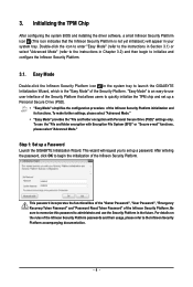
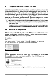
... the Security Platform that the Infineon Security Platform is an easy-to quickly initialize the TPM chip and set up a Password Launch the GIGABYTE Initialization Wizard. For details on the rules of the Security Platform. To make further settings, please select "Advanced Mode." • ... Security Platform initialization and its functions. 3. This wizard will appear in the future. Initializing the TPM Chip After configuring the system BIOS and installing the driver software, a small Infineon Security Platform icon (This icon indicates that allows users to -use the "File ...
... the Security Platform that the Infineon Security Platform is an easy-to quickly initialize the TPM chip and set up a Password Launch the GIGABYTE Initialization Wizard. For details on the rules of the Security Platform. To make further settings, please select "Advanced Mode." • ... Security Platform initialization and its functions. 3. This wizard will appear in the future. Initializing the TPM Chip After configuring the system BIOS and installing the driver software, a small Infineon Security Platform icon (This icon indicates that allows users to -use the "File ...
Manual
Page 16
... To create a Portable User Key, right-click on a USB flash drive (or in a secure location and back them up a Personal Secure Drive (PSD). GIGABYTE is not liable for Using Ultra TPM Before launching the Ultra TPM utility, make sure the TPM chip has been initialized and you have encrypted...render the files encrypted via the TPM unable to BIOS check box, or select at least set up their keys in the BIOS, the latter key will appear in the system BIOS. With the easy-to set up . Configuring the GIGABYTE Ultra TPM Utility GIGABYTE's unique Ultra TPM (Trusted Platform Module) supports ...
... To create a Portable User Key, right-click on a USB flash drive (or in a secure location and back them up a Personal Secure Drive (PSD). GIGABYTE is not liable for Using Ultra TPM Before launching the Ultra TPM utility, make sure the TPM chip has been initialized and you have encrypted...render the files encrypted via the TPM unable to BIOS check box, or select at least set up their keys in the BIOS, the latter key will appear in the system BIOS. With the easy-to set up . Configuring the GIGABYTE Ultra TPM Utility GIGABYTE's unique Ultra TPM (Trusted Platform Module) supports ...
Manual
Page 17
... drive, right-click on the Ultra TPM icon and select Duplicate. You are able to "Enabled/Activate." Duplicate... Step 3: Enter the User Password created in BIOS Setup and then set "Security Chip" to load or unload your computer before the uninstallation. - 17 - To be sure to continue. Click OK to insert...
... drive, right-click on the Ultra TPM icon and select Duplicate. You are able to "Enabled/Activate." Duplicate... Step 3: Enter the User Password created in BIOS Setup and then set "Security Chip" to load or unload your computer before the uninstallation. - 17 - To be sure to continue. Click OK to insert...
Manual
Page 3
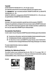
... to use of this manual may be reproduced, copied, translated, transmitted, or published in this manual are legally registered to GIGABYTE UNITED INC. The logo is the property of the product, read the Quick Installation Guide included with the product. „...your motherboard revision before updating motherboard BIOS, drivers, or when looking for technical information. GIGABYTE UNITED INC. For example, "REV: 1.0" means the revision of this product, GIGABYTE provides the following types of documentations: „ For quick set-up of GIGABYTE. Example: All rights reserved....
... to use of this manual may be reproduced, copied, translated, transmitted, or published in this manual are legally registered to GIGABYTE UNITED INC. The logo is the property of the product, read the Quick Installation Guide included with the product. „...your motherboard revision before updating motherboard BIOS, drivers, or when looking for technical information. GIGABYTE UNITED INC. For example, "REV: 1.0" means the revision of this product, GIGABYTE provides the following types of documentations: „ For quick set-up of GIGABYTE. Example: All rights reserved....
Manual
Page 4
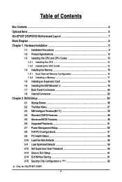
Table of Contents Box Contents ...6 OptionalItems ...6 GA-EP45T-DS3R/DS3 Motherboard Layout 7 Block Diagram ...8 Chapter 1 Hardware Installation 9 1-1 Installation Precautions 9 1-2 Product Specifications 10 1-3 Installing the CPU and CPU Cooler...Installing the SATA Bracket 19 1-7 Back Panel Connectors 20 1-8 Internal Connectors 22 Chapter 2 BIOS Setup 35 2-1 Startup Screen 36 2-2 The Main Menu 37 2-3 MB Intelligent Tweaker(M.I.T 39 2-4 Standard CMOS Features 46 2-5 Advanced BIOS Features 48 2-6 IntegratedPeripherals 51 2-7 Power Management Setup 55 2-8 PnP/PCI Configurations 57 ...
Table of Contents Box Contents ...6 OptionalItems ...6 GA-EP45T-DS3R/DS3 Motherboard Layout 7 Block Diagram ...8 Chapter 1 Hardware Installation 9 1-1 Installation Precautions 9 1-2 Product Specifications 10 1-3 Installing the CPU and CPU Cooler...Installing the SATA Bracket 19 1-7 Back Panel Connectors 20 1-8 Internal Connectors 22 Chapter 2 BIOS Setup 35 2-1 Startup Screen 36 2-2 The Main Menu 37 2-3 MB Intelligent Tweaker(M.I.T 39 2-4 Standard CMOS Features 46 2-5 Advanced BIOS Features 48 2-6 IntegratedPeripherals 51 2-7 Power Management Setup 55 2-8 PnP/PCI Configurations 57 ...

Manual
Page 5
...64 3-4 Contact ...65 3-5 System ...65 3-6 Download Center 66 Chapter 4 Unique Features 67 4-1 Xpress Recovery2 67 4-2 BIOS Update Utilities 72 4-2-1 Updating the BIOS with the Q-Flash Utility 72 4-2-2 Updating the BIOS with the @BIOS Utility 75 4-3 EasyTune 6 ...76 4-4 Dynamic Energy Saver Advanced 77 4-5 Ultra TPM (Note 79 4-6 Q-Share ...80... the Sound Recorder 105 5-3 Troubleshooting 106 5-3-1 Frequently Asked Questions 106 5-3-2 Troubleshooting Procedure 107 Regulatory Statements 109 Only for GA-EP45T-DS3R. (Note) This feature is optional due to different regional policy. - 5 -
...64 3-4 Contact ...65 3-5 System ...65 3-6 Download Center 66 Chapter 4 Unique Features 67 4-1 Xpress Recovery2 67 4-2 BIOS Update Utilities 72 4-2-1 Updating the BIOS with the Q-Flash Utility 72 4-2-2 Updating the BIOS with the @BIOS Utility 75 4-3 EasyTune 6 ...76 4-4 Dynamic Energy Saver Advanced 77 4-5 Ultra TPM (Note 79 4-6 Q-Share ...80... the Sound Recorder 105 5-3 Troubleshooting 106 5-3-1 Frequently Asked Questions 106 5-3-2 Troubleshooting Procedure 107 Regulatory Statements 109 Only for GA-EP45T-DS3R. (Note) This feature is optional due to different regional policy. - 5 -
Manual
Page 8
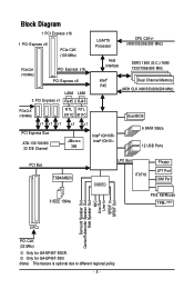
.../1066/800 MHz Intel® P45 Dual Channel Memory MCH CLK (400/333/266/200 MHz) PCIe CLK (100 MHz) RTL RTL 8111C 8111C Dual BIOS x1 x1 x1 PCI Express Bus ATA-133/100/66/ 33 IDE Channel x1 x1 JMicron 368 Intel® ICH10R Intel® ICH10 6 SATA 3Gb... Speaker Out Center/Subwoofer Speaker Out Side Speaker Out MIC Line-Out Line-In SPDIF In SPDIF Out 2 PCI PCI CLK (33 MHz) Only for GA-EP45T-DS3. (Note) This feature is optional due to different regional policy. - 8 - Only for GA-EP45T-DS3R.
.../1066/800 MHz Intel® P45 Dual Channel Memory MCH CLK (400/333/266/200 MHz) PCIe CLK (100 MHz) RTL RTL 8111C 8111C Dual BIOS x1 x1 x1 PCI Express Bus ATA-133/100/66/ 33 IDE Channel x1 x1 JMicron 368 Intel® ICH10R Intel® ICH10 6 SATA 3Gb... Speaker Out Center/Subwoofer Speaker Out Side Speaker Out MIC Line-Out Line-In SPDIF In SPDIF Out 2 PCI PCI CLK (33 MHz) Only for GA-EP45T-DS3. (Note) This feature is optional due to different regional policy. - 8 - Only for GA-EP45T-DS3R.
Manual
Page 12
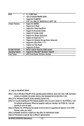
...more than 4 GB of physical memory is installed, the actual memory size displayed will be sure to different regional policy. GA-EP45T-DS3R/DS3 Motherboard - 12 - BIOS Unique Features Bundled Software Operating System Form Factor Š 2 x 8 Mbit flash Š Use of licensed AWARD... BIOS Š Support for DualBIOSTM Š PnP 1.0a, DMI 2.0, SM BIOS 2.4, ACPI 1.0b Š Support for @BIOS Š Support for Q-Flash Š Support for Virtual Dual BIOS Š Support for Download Center Š Support for Xpress Install Š ...
...more than 4 GB of physical memory is installed, the actual memory size displayed will be sure to different regional policy. GA-EP45T-DS3R/DS3 Motherboard - 12 - BIOS Unique Features Bundled Software Operating System Form Factor Š 2 x 8 Mbit flash Š Use of licensed AWARD... BIOS Š Support for DualBIOSTM Š PnP 1.0a, DMI 2.0, SM BIOS 2.4, ACPI 1.0b Š Support for @BIOS Š Support for Q-Flash Š Support for Virtual Dual BIOS Š Support for Download Center Š Support for Xpress Install Š ...

Manual
Page 16
... modules of different capacity and chips are installed, a message which says memory is installed, the BIOS will automatically detect the specifications and capacity of the memory. DS/SS - - - - DS...DDR3 memory module is installed. 2. Dual Channel mode cannot be used . (Go to GIGABYTE's website for optimum performance. • Each channel can be populated and remain in Dual... DDR3_3 DDR3_4 Due to prevent hardware damage. • Memory modules have a foolproof design. GA-EP45T-DS3R/DS3 Motherboard - 16 - The four DDR3 memory sockets are divided into two channels and each...
... modules of different capacity and chips are installed, a message which says memory is installed, the BIOS will automatically detect the specifications and capacity of the memory. DS/SS - - - - DS...DDR3 memory module is installed. 2. Dual Channel mode cannot be used . (Go to GIGABYTE's website for optimum performance. • Each channel can be populated and remain in Dual... DDR3_3 DDR3_4 Due to prevent hardware damage. • Memory modules have a foolproof design. GA-EP45T-DS3R/DS3 Motherboard - 16 - The four DDR3 memory sockets are divided into two channels and each...

Manual
Page 18
... the expansion slot. 1. After installing all expansion cards, replace the chassis cover(s). 6. Secure the card's metal bracket to make any required BIOS changes for your computer. Locate an expansion slot that came with the expansion card in the slot and does not rock. • Removing...If necessary, go to BIOS Setup to the chassis back panel with the slot, and press down on your expansion card(s). 7. Turn on the top edge of the PCI Express slot to install an expansion card: • Make sure the motherboard supports the expansion card. GA-EP45T-DS3R/DS3 Motherboard - 18...
... the expansion slot. 1. After installing all expansion cards, replace the chassis cover(s). 6. Secure the card's metal bracket to make any required BIOS changes for your computer. Locate an expansion slot that came with the expansion card in the slot and does not rock. • Removing...If necessary, go to BIOS Setup to the chassis back panel with the slot, and press down on your expansion card(s). 7. Turn on the top edge of the PCI Express slot to install an expansion card: • Make sure the motherboard supports the expansion card. GA-EP45T-DS3R/DS3 Motherboard - 18...
Manual
Page 27
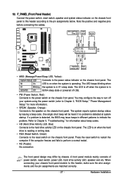
... single short beep will be heard if no problem is in S1 sleep state. The LED is on when the hard drive is detected, the BIOS may differ by issuing a beep code. Message/Power/ Power Sleep LED Switch Speaker MSG+ MSG- You may configure the way to turn off when the...status indicator on the chassis front panel. PW+ PWSPEAK+ SPEAK- 2 20 1 19 HD+ HD- When connecting your system using the power switch (refer to Chapter 2, "BIOS Setup," "Power Management Setup," for information about beep codes. • HD (Hard Drive Activity LED, Blue) Connects to the pin assignments below.
... single short beep will be heard if no problem is in S1 sleep state. The LED is on when the hard drive is detected, the BIOS may differ by issuing a beep code. Message/Power/ Power Sleep LED Switch Speaker MSG+ MSG- You may configure the way to turn off when the...status indicator on the chassis front panel. PW+ PWSPEAK+ SPEAK- 2 20 1 19 HD+ HD- When connecting your system using the power switch (refer to Chapter 2, "BIOS Setup," "Power Management Setup," for information about beep codes. • HD (Hard Drive Activity LED, Blue) Connects to the pin assignments below.


