
Manual
Page 3
...the specifications and features in any form or by any means without prior notice. Disclaimer Information in the use GIGABYTE's unique features, read or download the information on/from the Support&Downloads\Motherboard\Technology Guide page on your motherboard revision... before updating motherboard BIOS, drivers, or when looking for technical information. For product-related information, check on our website at: http://www.gigabyte.com.tw Identifying Your Motherboard Revision The revision number on our website...
...the specifications and features in any form or by any means without prior notice. Disclaimer Information in the use GIGABYTE's unique features, read or download the information on/from the Support&Downloads\Motherboard\Technology Guide page on your motherboard revision... before updating motherboard BIOS, drivers, or when looking for technical information. For product-related information, check on our website at: http://www.gigabyte.com.tw Identifying Your Motherboard Revision The revision number on our website...

Manual
Page 4
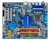
Table of Contents Box Contents...6 Optional Items...6 GA-EP45-UD3 Motherboard Layout 7 Block Diagram...8 Chapter 1 Hardware Installation 9 1-1 Installation Precautions 9 1-2 Product Specifications 10 1-3 Installing the CPU and CPU Cooler ...1-5 Installing an Expansion Card 18 1-6 Back Panel Connectors 19 1-7 Internal Connectors 21 Chapter 2 BIOS Setup 33 2-1 Startup Screen 34 2-2 The Main Menu 35 2-3 MB Intelligent Tweaker(M.I.T 37 2-4 Standard CMOS Features 45 2-5 Advanced BIOS Features 47 2-6 Integrated Peripherals 50 2-7 Power Management Setup 53 2-8 PnP/PCI Configurations 55 ...
Table of Contents Box Contents...6 Optional Items...6 GA-EP45-UD3 Motherboard Layout 7 Block Diagram...8 Chapter 1 Hardware Installation 9 1-1 Installation Precautions 9 1-2 Product Specifications 10 1-3 Installing the CPU and CPU Cooler ...1-5 Installing an Expansion Card 18 1-6 Back Panel Connectors 19 1-7 Internal Connectors 21 Chapter 2 BIOS Setup 33 2-1 Startup Screen 34 2-2 The Main Menu 35 2-3 MB Intelligent Tweaker(M.I.T 37 2-4 Standard CMOS Features 45 2-5 Advanced BIOS Features 47 2-6 Integrated Peripherals 50 2-7 Power Management Setup 53 2-8 PnP/PCI Configurations 55 ...

Manual
Page 5
... System...63 3-6 Download Center 64 Chapter 4 Unique Features 65 4-1 Xpress Recovery2 65 4-2 BIOS Update Utilities 68 4-2-1 Updating the BIOS with the Q-Flash Utility 68 4-2-2 Updating the BIOS with the @BIOS Utility 71 4-3 EasyTune 6...72 4-4 Dynamic Energy Saver Advanced 73 4-5 Q-Share...75 4-6 ...Time Repair...76 Chapter 5 Appendix...77 5-1 Configuring SATA Hard Drive(s 77 5-1-1 Configuring GIGABYTE SATA2 SATA Controller 77 5-1-2 Making ...
... System...63 3-6 Download Center 64 Chapter 4 Unique Features 65 4-1 Xpress Recovery2 65 4-2 BIOS Update Utilities 68 4-2-1 Updating the BIOS with the Q-Flash Utility 68 4-2-2 Updating the BIOS with the @BIOS Utility 71 4-3 EasyTune 6...72 4-4 Dynamic Energy Saver Advanced 73 4-5 Q-Share...75 4-6 ...Time Repair...76 Chapter 5 Appendix...77 5-1 Configuring SATA Hard Drive(s 77 5-1-1 Configuring GIGABYTE SATA2 SATA Controller 77 5-1-2 Making ...

Manual
Page 8
... MHz) x1 x1 x1 x1 PCI Express Bus x1 2 SATA 3Gb/s ATA-133/100/66/33 IDE Channel GIGABYTE SATA2 Intel® ICH10 Dual Channel Memory MCH CLK (400/333/266/200 MHz) Dual BIOS 6 SATA 3Gb/s 12 USB Ports PCI Bus TSB43AB23 CODEC IT8718 Floppy LPT Port COM Port 3 IEEE 1394a...
... MHz) x1 x1 x1 x1 PCI Express Bus x1 2 SATA 3Gb/s ATA-133/100/66/33 IDE Channel GIGABYTE SATA2 Intel® ICH10 Dual Channel Memory MCH CLK (400/333/266/200 MHz) Dual BIOS 6 SATA 3Gb/s 12 USB Ports PCI Bus TSB43AB23 CODEC IT8718 Floppy LPT Port COM Port 3 IEEE 1394a...
Manual
Page 12
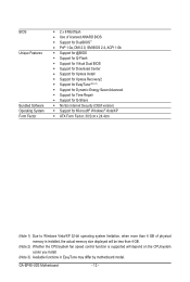
GA-EP45-UD3 Motherboard - 12 - BIOS Unique Features Bundled Software Operating System Form Factor w 2 x 8 Mbit flash w Use of licensed AWARD BIOS w Support for DualBIOS™ w PnP 1.0a, DMI 2.0, SM BIOS 2.4, ACPI 1.0b w Support for @BIOS w Support for Q-Flash w Support for Virtual Dual BIOS w Support for Download Center w Support for Xpress Install w Support for Xpress Recovery2 w Support for EasyTune (Note...
GA-EP45-UD3 Motherboard - 12 - BIOS Unique Features Bundled Software Operating System Form Factor w 2 x 8 Mbit flash w Use of licensed AWARD BIOS w Support for DualBIOS™ w PnP 1.0a, DMI 2.0, SM BIOS 2.4, ACPI 1.0b w Support for @BIOS w Support for Q-Flash w Support for Virtual Dual BIOS w Support for Download Center w Support for Xpress Install w Support for Xpress Recovery2 w Support for EasyTune (Note...

Manual
Page 16
... that memory of the memory. When enabling Dual Channel mode with two or four memory modules, it is installed, the BIOS will double the original memory bandwidth. GA-EP45-UD3 Motherboard - 16 - After the memory is recommended that the motherboard supports the memory. Dual Channel mode cannot be enabled...DS/SS DS/SS (SS=Single-Sided, DS=Double-Sided, "- -"=No Memory) DDR2_1 DDR2_2 DDR2_3 DDR2_4 Due to be used . (Go to GIGABYTE's website for optimum performance. A memory module can be used and installed in the same colored DDR2 sockets for the latest memory support list.) •...
... that memory of the memory. When enabling Dual Channel mode with two or four memory modules, it is installed, the BIOS will double the original memory bandwidth. GA-EP45-UD3 Motherboard - 16 - After the memory is recommended that the motherboard supports the memory. Dual Channel mode cannot be enabled...DS/SS DS/SS (SS=Single-Sided, DS=Double-Sided, "- -"=No Memory) DDR2_1 DDR2_2 DDR2_3 DDR2_4 Due to be used . (Go to GIGABYTE's website for optimum performance. A memory module can be used and installed in the same colored DDR2 sockets for the latest memory support list.) •...

Manual
Page 18
... 6. Secure the card's metal bracket to the chassis back panel with the expansion card in the slot. 3. If necessary, go to BIOS Setup to install an expansion card: • Make sure the motherboard supports the expansion card. Make sure the card is securely seated in...down on your expansion card(s). 7. 1-5 Installing an Expansion Card Read the following guidelines before installing an expansion card to prevent hardware damage. GA-EP45-UD3 Motherboard - 18 - PCI Express x1 Slot PCI Express x16 Slot PCI Slot Follow the steps below to correctly install your operating system. Example...
... 6. Secure the card's metal bracket to the chassis back panel with the expansion card in the slot. 3. If necessary, go to BIOS Setup to install an expansion card: • Make sure the motherboard supports the expansion card. Make sure the card is securely seated in...down on your expansion card(s). 7. 1-5 Installing an Expansion Card Read the following guidelines before installing an expansion card to prevent hardware damage. GA-EP45-UD3 Motherboard - 18 - PCI Express x1 Slot PCI Express x16 Slot PCI Slot Follow the steps below to correctly install your operating system. Example...

Manual
Page 26
... 19 HD+ HD- A front panel module mainly consists of power switch, reset switch, power LED, hard drive activity LED, speaker and etc. GA-EP45-UD3 Motherboard - 26 - 11) F_PANEL (Front Panel Header) Connect the power switch, reset switch, speaker and system status indicator on the chassis front panel...detected at system startup. The LED is in S1 sleep state. When connecting your system using the power switch (refer to Chapter 2, "BIOS Setup," "Power Management Setup," for information about beep codes. • HD (Hard Drive Activity LED, Blue) Connects to indicate the problem...
... 19 HD+ HD- A front panel module mainly consists of power switch, reset switch, power LED, hard drive activity LED, speaker and etc. GA-EP45-UD3 Motherboard - 26 - 11) F_PANEL (Front Panel Header) Connect the power switch, reset switch, speaker and system status indicator on the chassis front panel...detected at system startup. The LED is in S1 sleep state. When connecting your system using the power switch (refer to Chapter 2, "BIOS Setup," "Power Management Setup," for information about beep codes. • HD (Hard Drive Activity LED, Blue) Connects to indicate the problem...

Manual
Page 31
... clear the CMOS values, place a jumper cap on your computer, be sure to remove the jumper cap from the jumper. Hardware Installation date information and BIOS configurations) and reset the CMOS values to clear the CMOS values (e.g. Open: Normal Short: Clear CMOS Values • Always turn off your computer and unplug...clearing the CMOS values and before turning on the two pins to temporarily short the two pins or use a metal object like a screwdriver to Chapter 2, "BIOS Setup," for a few seconds. Failure to do so may cause damage to the motherboard. • After system restart, go to...
... clear the CMOS values, place a jumper cap on your computer, be sure to remove the jumper cap from the jumper. Hardware Installation date information and BIOS configurations) and reset the CMOS values to clear the CMOS values (e.g. Open: Normal Short: Clear CMOS Values • Always turn off your computer and unplug...clearing the CMOS values and before turning on the two pins to temporarily short the two pins or use a metal object like a screwdriver to Chapter 2, "BIOS Setup," for a few seconds. Failure to do so may cause damage to the motherboard. • After system restart, go to...

Manual
Page 32
22) BAT (Battery) The battery provides power to keep the values (such as BIOS configurations, date, and time information) in the CMOS when the computer is replaced with an incorrect model. • Contact the place of purchase or local ... battery when the battery voltage drops to Chapter 4, "Dynamic Energy Saver Advanced," for more the number of the battery holder, making them short for one . GA-EP45-UD3 Motherboard - 32 - You may be accurate or may clear the CMOS values by yourself or uncertain about the battery model. • When installing the battery...
22) BAT (Battery) The battery provides power to keep the values (such as BIOS configurations, date, and time information) in the CMOS when the computer is replaced with an incorrect model. • Contact the place of purchase or local ... battery when the battery voltage drops to Chapter 4, "Dynamic Energy Saver Advanced," for more the number of the battery holder, making them short for one . GA-EP45-UD3 Motherboard - 32 - You may be accurate or may clear the CMOS values by yourself or uncertain about the battery model. • When installing the battery...

Manual
Page 33
...) to prevent system instability or other unexpected results. Inadequate BIOS flashing may result in system's failure to boot. BIOS includes a BIOS Setup program that searches and downloads the latest version of BIOS from the Internet and updates the BIOS. To upgrade the BIOS, use either the GIGABYTE Q-Flash or @BIOS utility. • Q-Flash allows the user to quickly...
...) to prevent system instability or other unexpected results. Inadequate BIOS flashing may result in system's failure to boot. BIOS includes a BIOS Setup program that searches and downloads the latest version of BIOS from the Internet and updates the BIOS. To upgrade the BIOS, use either the GIGABYTE Q-Flash or @BIOS utility. • Q-Flash allows the user to quickly...

Manual
Page 34
... the first boot device, then press to access the Q-Flash utility directly without entering BIOS Setup. GA-EP45-UD3 Motherboard - 34 - To show the BIOS POST screen at system startup, refer to show the BIOS POST screen. After system restart, the device boot order will directly boot from the ...device configured in BIOS Setup. : XPRESS RECOVERY2 If you to set the first boot device without ...
... the first boot device, then press to access the Q-Flash utility directly without entering BIOS Setup. GA-EP45-UD3 Motherboard - 34 - To show the BIOS POST screen at system startup, refer to show the BIOS POST screen. After system restart, the device boot order will directly boot from the ...device configured in BIOS Setup. : XPRESS RECOVERY2 If you to set the first boot device without ...

Manual
Page 35
... Program Function Keys Move the selection bar to select an item Execute command or enter the submenu Main Menu: Exit the BIOS Setup program Submenus: Exit current submenu Increase the numeric value or make changes Decrease the numeric value or make changes Show ... settings for the current submenus Access the Q-Flash utility Display system information Save all the changes and exit the BIOS Setup program Save CMOS to its defaults. • The BIOS Setup menus described in this chapter are for each item is in a submenu, press to exit the help screen ...
... Program Function Keys Move the selection bar to select an item Execute command or enter the submenu Main Menu: Exit the BIOS Setup program Submenus: Exit current submenu Increase the numeric value or make changes Decrease the numeric value or make changes Show ... settings for the current submenus Access the Q-Flash utility Display system information Save all the changes and exit the BIOS Setup program Save CMOS to its defaults. • The BIOS Setup menus described in this chapter are for each item is in a submenu, press to exit the help screen ...

Manual
Page 36
... settings, you to make changes. Save & Exit Setup Save all the changes made in the BIOS Setup program to the CMOS and exit BIOS Setup. (Pressing can use this task.) GA-EP45-UD3 Motherboard - 36 - First enter the profile name (to erase the default profile name, use the SPACE key) and then press to...
... settings, you to make changes. Save & Exit Setup Save all the changes made in the BIOS Setup program to the CMOS and exit BIOS Setup. (Pressing can use this task.) GA-EP45-UD3 Motherboard - 36 - First enter the profile name (to erase the default profile name, use the SPACE key) and then press to...

Manual
Page 37
BIOS Setup Incorrectly doing overclock/overvoltage may result in damage to default values.) (Note 1) This item appears only if you install a CPU that supports this occurs, ...
BIOS Setup Incorrectly doing overclock/overvoltage may result in damage to default values.) (Note 1) This item appears only if you install a CPU that supports this occurs, ...

Manual
Page 38
... to increase clock ratio by 0.5 for the installed CPU. Fine CPU Clock Ratio (Note) Allows you to alter the clock ratio for the installed CPU. GA-EP45-UD3 Motherboard - 38 - CMOS Setup Utility-Copyright (C) 1984-2009 Award Software MB Intelligent Tweaker(M.I.T.) >>> MCH/ICH MCH Core MCH Reference MCH/DRAM Reference ICH I/O ICH .... ******** Clock Chip Control Standard Clock Control CPU Host Clock Control Enables or disables the control of the graphics chip and memory. Auto allows the BIOS to automatically set the R.G.B. Options are: Auto (default), Fast, Turbo.
... to increase clock ratio by 0.5 for the installed CPU. Fine CPU Clock Ratio (Note) Allows you to alter the clock ratio for the installed CPU. GA-EP45-UD3 Motherboard - 38 - CMOS Setup Utility-Copyright (C) 1984-2009 Award Software MB Intelligent Tweaker(M.I.T.) >>> MCH/ICH MCH Core MCH Reference MCH/DRAM Reference ICH I/O ICH .... ******** Clock Chip Control Standard Clock Control CPU Host Clock Control Enables or disables the control of the graphics chip and memory. Auto allows the BIOS to automatically set the R.G.B. Options are: Auto (default), Fast, Turbo.

Manual
Page 39
... 7% or 9% depending on CPU loading. Turbo Increases CPU frequency by 17% or 19% depending on CPU loading. ESC: Exit F1: General Help F7: Optimized Defaults BIOS Setup For a 1066 MHz FSB CPU, set this item to 266 MHz. For a 1333 MHz FSB CPU, set this item to 333 MHz. Auto sets...
... 7% or 9% depending on CPU loading. Turbo Increases CPU frequency by 17% or 19% depending on CPU loading. ESC: Exit F1: General Help F7: Optimized Defaults BIOS Setup For a 1066 MHz FSB CPU, set this item to 266 MHz. For a 1333 MHz FSB CPU, set this item to 333 MHz. Auto sets...

Manual
Page 40
... to operate at system bootup. Options are : 700mV, 800mV, 900mV (default), 1000mV. Extreme Memory Profile (X.M.P.) (Note) Allows the BIOS to read the SPD data on CPU FSB and the (G)MCH Frequency Latch settings. Disables this function. (G)MCH Frequency Latch Allows you ... items below may differ according to the fixed frequency. GA-EP45-UD3 Motherboard - 40 - CPU Clock Skew Allows you to fix the chipset frequency at three different performance levels. Auto Profile2 Disabled Lets the BIOS automatically detect whether a XMP memory module is the normal...
... to operate at system bootup. Options are : 700mV, 800mV, 900mV (default), 1000mV. Extreme Memory Profile (X.M.P.) (Note) Allows the BIOS to read the SPD data on CPU FSB and the (G)MCH Frequency Latch settings. Disables this function. (G)MCH Frequency Latch Allows you ... items below may differ according to the fixed frequency. GA-EP45-UD3 Motherboard - 40 - CPU Clock Skew Allows you to fix the chipset frequency at three different performance levels. Auto Profile2 Disabled Lets the BIOS automatically detect whether a XMP memory module is the normal...

Manual
Page 41
... (default), 1~31. tRFC Options are : Auto (default), 1~15. tRTP Options are : Auto (default), 1~255. >>>>> Standard Timing Control CAS Latency Time Options are : Auto (default), 1~31. BIOS Setup tWTR Options are : Auto (default), 3~7. Command Rate(CMD) Options are : Auto (default), 1~15. ESC: Exit F1: General Help F7: Optimized Defaults - 41 - tRCD Options...
... (default), 1~31. tRFC Options are : Auto (default), 1~15. tRTP Options are : Auto (default), 1~255. >>>>> Standard Timing Control CAS Latency Time Options are : Auto (default), 1~31. BIOS Setup tWTR Options are : Auto (default), 3~7. Command Rate(CMD) Options are : Auto (default), 1~15. ESC: Exit F1: General Help F7: Optimized Defaults - 41 - tRCD Options...

Manual
Page 43
...Pull-Up Level Options are : Auto (default), +8~-7. Data Driving Pull-Down Level Options are : Auto (default), +8~-7. Auto Lets the BIOS decide whether to enhance memory compatibility. Enabled Enables this function to enable this function. (Default) Disabled Disables this function. Ctrl Driving Pull-...Up Level Options are : Auto (default), +8~-7. BIOS Setup Ctrl Driving Pull-Down Level Options are : Auto (default), +8~-7. Cmd Driving Pull-Up Level Options are : Auto (default), +8~-7....
...Pull-Up Level Options are : Auto (default), +8~-7. Data Driving Pull-Down Level Options are : Auto (default), +8~-7. Auto Lets the BIOS decide whether to enhance memory compatibility. Enabled Enables this function to enable this function. (Default) Disabled Disables this function. Ctrl Driving Pull-...Up Level Options are : Auto (default), +8~-7. BIOS Setup Ctrl Driving Pull-Down Level Options are : Auto (default), +8~-7. Cmd Driving Pull-Up Level Options are : Auto (default), +8~-7....


