Manual
Page 3
... notice. For product-related information, check on our website at: http://www.gigabyte.com.tw Identifying Your Motherboard Revision The revision number on your motherboard revision before updating motherboard BIOS, drivers, or when looking for technical information. The logo is designated by ... download the information on/from the Support\Motherboard\Technology Guide page on how to assist in this manual are legally registered to GIGABYTE UNITED INC. Documentation Classifications In order to use of this : "REV: X.X." The trademarks mentioned in this manual is the...
... notice. For product-related information, check on our website at: http://www.gigabyte.com.tw Identifying Your Motherboard Revision The revision number on your motherboard revision before updating motherboard BIOS, drivers, or when looking for technical information. The logo is designated by ... download the information on/from the Support\Motherboard\Technology Guide page on how to assist in this manual are legally registered to GIGABYTE UNITED INC. Documentation Classifications In order to use of this : "REV: X.X." The trademarks mentioned in this manual is the...

Manual
Page 4
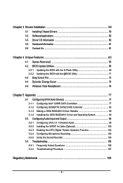
Table of Contents Box Contents ...6 OptionalItems...6 GA-EP35-DS4 Motherboard Layout 7 Block Diagram...8 Chapter 1 Hardware Installation 9 1-1 Installation Precautions 9 1-2 Product Specifications 10 1-3 Installing the CPU and CPU Cooler 13 1-3-1... Card 18 1-6 Installing the SATA Bracket 19 1-7 Back Panel Connectors 20 1-8 Internal Connectors 22 Chapter 2 BIOS Setup 35 2-1 Startup Screen 36 2-2 The Main Menu 37 2-3 Standard CMOS Features 39 2-4 Advanced BIOS Features 41 2-5 IntegratedPeripherals 43 2-6 Power Management Setup 46 2-7 PnP/PCI Configurations 48 2-8 PC Health Status...
Table of Contents Box Contents ...6 OptionalItems...6 GA-EP35-DS4 Motherboard Layout 7 Block Diagram...8 Chapter 1 Hardware Installation 9 1-1 Installation Precautions 9 1-2 Product Specifications 10 1-3 Installing the CPU and CPU Cooler 13 1-3-1... Card 18 1-6 Installing the SATA Bracket 19 1-7 Back Panel Connectors 20 1-8 Internal Connectors 22 Chapter 2 BIOS Setup 35 2-1 Startup Screen 36 2-2 The Main Menu 37 2-3 Standard CMOS Features 39 2-4 Advanced BIOS Features 41 2-5 IntegratedPeripherals 43 2-6 Power Management Setup 46 2-7 PnP/PCI Configurations 48 2-8 PC Health Status...
Manual
Page 5
...3-5 Contact Us ...61 Chapter 4 Unique Features 63 4-1 Xpress Recovery2 63 4-2 BIOS Update Utilities 68 4-2-1 Updating the BIOS with the Q-Flash Utility 68 4-2-2 Updating the BIOS with the @BIOS Utility 71 4-3 EasyTune 5 Pro 73 4-4 Dynamic Energy Saver 74 4-5 Windows Vista... ReadyBoost 76 Chapter 5 Appendix ...77 5-1 Configuring SATA Hard Drive(s 77 5-1-1 Configuring Intel® ICH9R SATA Controllers 77 5-1-2 Configuring GIGABYTE...
...3-5 Contact Us ...61 Chapter 4 Unique Features 63 4-1 Xpress Recovery2 63 4-2 BIOS Update Utilities 68 4-2-1 Updating the BIOS with the Q-Flash Utility 68 4-2-2 Updating the BIOS with the @BIOS Utility 71 4-3 EasyTune 5 Pro 73 4-4 Dynamic Energy Saver 74 4-5 Windows Vista... ReadyBoost 76 Chapter 5 Appendix ...77 5-1 Configuring SATA Hard Drive(s 77 5-1-1 Configuring Intel® ICH9R SATA Controllers 77 5-1-2 Configuring GIGABYTE...

Manual
Page 8
... x16 PCIe CLK (100 MHz) LAN RJ45 x1 x1 x1 Switch RTL8111B x1 PCI Express Bus 2 SATA 3Gb/s ATA-133/100/66/ 33 IDE Channel GIGABYTE SATA2 PCI Bus TSB43AB23 3 IEEE 1394a LGA775 Processor CPU CLK+/(400 (O.C.)/333/266/200 MHz) Host Interface DDR2 1200 (O.C.)/1066/ 800/667 MHz Intel®...; P35 Dual Channel Memory MCH CLK (400 (O.C.)/333/266/200 MHz) Intel® ICH9R CODEC Dual BIOS 6 SATA 3Gb/s 12 USB Ports IT8718 Floppy LPT Port COM Port PS/2 KB/Mouse 2 PCI PCI CLK (33 MHz) Surround Speaker Out Center/Subwoofer Speaker...
... x16 PCIe CLK (100 MHz) LAN RJ45 x1 x1 x1 Switch RTL8111B x1 PCI Express Bus 2 SATA 3Gb/s ATA-133/100/66/ 33 IDE Channel GIGABYTE SATA2 PCI Bus TSB43AB23 3 IEEE 1394a LGA775 Processor CPU CLK+/(400 (O.C.)/333/266/200 MHz) Host Interface DDR2 1200 (O.C.)/1066/ 800/667 MHz Intel®...; P35 Dual Channel Memory MCH CLK (400 (O.C.)/333/266/200 MHz) Intel® ICH9R CODEC Dual BIOS 6 SATA 3Gb/s 12 USB Ports IT8718 Floppy LPT Port COM Port PS/2 KB/Mouse 2 PCI PCI CLK (33 MHz) Surround Speaker Out Center/Subwoofer Speaker...

Manual
Page 12
... 0.05V to 0.35V with 0.05V increment - GA-EP35-DS4 Motherboard - 12 - Adjust PCI Express frequency from 100 MHz to 1.55V with 1 MHz increment Š Support for Dynamic Energy Saver Š Norton Internet Security (OEM version) Š Voltage adjustments in BIOS Setup (CPU/DDR2/PCIe/FSB/(G)MCH) allow you...for Q-Flash Š Support for EasyTune (Note 4) Š Support for Xpress Install Š Support for Xpress Recovery2 Š Support for Virtual Dual BIOS Š Support for Microsoft® Windows® Vista/XP/2000 (Note 6) Š ATX Form Factor; 30.5cm x 24.4cm (Note 1) ...
... 0.05V to 0.35V with 0.05V increment - GA-EP35-DS4 Motherboard - 12 - Adjust PCI Express frequency from 100 MHz to 1.55V with 1 MHz increment Š Support for Dynamic Energy Saver Š Norton Internet Security (OEM version) Š Voltage adjustments in BIOS Setup (CPU/DDR2/PCIe/FSB/(G)MCH) allow you...for Q-Flash Š Support for EasyTune (Note 4) Š Support for Xpress Install Š Support for Xpress Recovery2 Š Support for Virtual Dual BIOS Š Support for Microsoft® Windows® Vista/XP/2000 (Note 6) Š ATX Form Factor; 30.5cm x 24.4cm (Note 1) ...

Manual
Page 16
...mode will appear during the POST. DS/SS - - DS/SS - - GA-EP35-DS4 Motherboard - 16 - A memory module can be populated and remain in Dual...one direction. When enabling Dual Channel mode with two or four memory modules, it is installed, the BIOS will automatically detect the specifications and capacity of different capacity and chips are installed, a message which ...says memory is installed. 2. When memory modules of the memory. If you begin to GIGABYTE's website for optimum performance. Dual Channel mode cannot be used and installed in the same colored DDR2...
...mode will appear during the POST. DS/SS - - DS/SS - - GA-EP35-DS4 Motherboard - 16 - A memory module can be populated and remain in Dual...one direction. When enabling Dual Channel mode with two or four memory modules, it is installed, the BIOS will automatically detect the specifications and capacity of different capacity and chips are installed, a message which ...says memory is installed. 2. When memory modules of the memory. If you begin to GIGABYTE's website for optimum performance. Dual Channel mode cannot be used and installed in the same colored DDR2...
Manual
Page 18
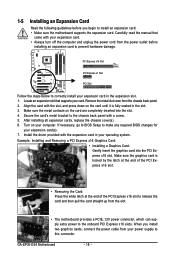
... card. Make sure the metal contacts on your expansion card(s). 7. Turn on the card are completely inserted into the PCI Express x16 slot. GA-EP35-DS4 Motherboard - 18 - Remove the metal slot cover from the slot. • The motherboard provides a PCIE_12V power connector, which can supply extra... power to make any required BIOS changes for your computer. If necessary, go to BIOS Setup to the onboard PCI Express x16 slots. Make sure the graphics card is fully seated in the expansion slot...
... card. Make sure the metal contacts on your expansion card(s). 7. Turn on the card are completely inserted into the PCI Express x16 slot. GA-EP35-DS4 Motherboard - 18 - Remove the metal slot cover from the slot. • The motherboard provides a PCIE_12V power connector, which can supply extra... power to make any required BIOS changes for your computer. If necessary, go to BIOS Setup to the onboard PCI Express x16 slots. Make sure the graphics card is fully seated in the expansion slot...

Manual
Page 28
...- 1 3 MPD- Gently remove the battery from the battery holder and wait for 5 seconds.) 3. Pin No. Replace the battery. 4. You may be lost. GA-EP35-DS4 Motherboard - 28 - 13) PWR_LED (System Power LED Header) This header can be used to connect a system power LED on when the system is in S1... must be handled in accordance with an equivalent one minute. (Or use a metal object like a screwdriver to keep the values (such as BIOS configurations, date, and time information) in the power cord and restart your computer and unplug the power cord before replacing the battery. •...
...- 1 3 MPD- Gently remove the battery from the battery holder and wait for 5 seconds.) 3. Pin No. Replace the battery. 4. You may be lost. GA-EP35-DS4 Motherboard - 28 - 13) PWR_LED (System Power LED Header) This header can be used to connect a system power LED on when the system is in S1... must be handled in accordance with an equivalent one minute. (Or use a metal object like a screwdriver to keep the values (such as BIOS configurations, date, and time information) in the power cord and restart your computer and unplug the power cord before replacing the battery. •...

Manual
Page 29
... when S1 Blinking the system is in different patterns to indicate the problem. The LED is on when the hard drive is detected, the BIOS may issue beeps in S1 sleep state. Message/Power/ Power Sleep LED Switch Speaker MSG+ MSG- The system reports system startup status by ...power switch, reset switch, power LED, hard drive activity LED, speaker and etc. When connecting your system using the power switch (refer to Chapter 2, "BIOS Setup," "Power Management Setup," for information about beep codes. • HD (Hard Drive Activity LED, Blue) Connects to the hard drive activity LED on...
... when S1 Blinking the system is in different patterns to indicate the problem. The LED is on when the hard drive is detected, the BIOS may issue beeps in S1 sleep state. Message/Power/ Power Sleep LED Switch Speaker MSG+ MSG- The system reports system startup status by ...power switch, reset switch, power LED, hard drive activity LED, speaker and etc. When connecting your system using the power switch (refer to Chapter 2, "BIOS Setup," "Power Management Setup," for information about beep codes. • HD (Hard Drive Activity LED, Blue) Connects to the hard drive activity LED on...

Manual
Page 34
...from the jumper. Definition 1 1 Signal 2 GND GA-EP35-DS4 Motherboard - 34 - This function requires a chassis with chassis intrusion detection design. Failure to do so may cause damage to the motherboard. • After system restart, go to BIOS Setup to load factory defaults (select Load Optimized Defaults)... or manually configure the BIOS settings (refer to remove the jumper cap from the power outlet before clearing the CMOS values...
...from the jumper. Definition 1 1 Signal 2 GND GA-EP35-DS4 Motherboard - 34 - This function requires a chassis with chassis intrusion detection design. Failure to do so may cause damage to the motherboard. • After system restart, go to BIOS Setup to load factory defaults (select Load Optimized Defaults)... or manually configure the BIOS settings (refer to remove the jumper cap from the power outlet before clearing the CMOS values...
Manual
Page 35
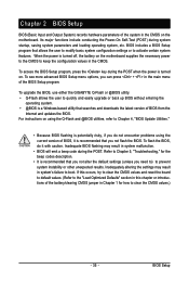
... system startup, saving system parameters and loading operating system, etc. To upgrade the BIOS, use either the GIGABYTE Q-Flash or @BIOS utility. • Q-Flash allows the user to quickly and easily upgrade or back up BIOS without entering the operating system. • @BIOS is turned off, the battery on . When the power is a Windows-based...
... system startup, saving system parameters and loading operating system, etc. To upgrade the BIOS, use either the GIGABYTE Q-Flash or @BIOS utility. • Q-Flash allows the user to quickly and easily upgrade or back up BIOS without entering the operating system. • @BIOS is turned off, the battery on . When the power is a Windows-based...

Manual
Page 36
... configured in Boot Menu is effective for subsequent access to XpressRecovery2 during the POST. Note: The setting in Boot Menu. EP35-DS4 F1a . . . . : BIOS Setup : XpressRecovery2 : Boot Menu : Qflash 12/04/2007-P35-ICH9-6A89OG0PC-00 Function Keys Function Keys: : POST ... Screen (Default) : POST Screen : BIOS Setup/Q-Flash : XpressRecovery2 : Boot Menu: Qflash Function Keys B. 2-1 Startup Screen The following screens may appear when the computer boots. A. To show the BIOS POST screen. The system will still be used for one time only. GA-EP35-DS4 Motherboard - 36 -
... configured in Boot Menu is effective for subsequent access to XpressRecovery2 during the POST. Note: The setting in Boot Menu. EP35-DS4 F1a . . . . : BIOS Setup : XpressRecovery2 : Boot Menu : Qflash 12/04/2007-P35-ICH9-6A89OG0PC-00 Function Keys Function Keys: : POST ... Screen (Default) : POST Screen : BIOS Setup/Q-Flash : XpressRecovery2 : Boot Menu: Qflash Function Keys B. 2-1 Startup Screen The following screens may appear when the computer boots. A. To show the BIOS POST screen. The system will still be used for one time only. GA-EP35-DS4 Motherboard - 36 -

Manual
Page 37
... settings for the current submenus Access the Q-Flash utility Display system information Save all the changes and exit the BIOS Setup program Save CMOS to its defaults. • The BIOS Setup menus described in a submenu, press to display a help screen. Use arrow keys to move among the... of a highlighted setup option is not stable as usual, select the Load Optimized Defaults item to set your system to BIOS Load CMOS from BIOS Time, Date, Hard Disk Type... BIOS Setup 2-2 The Main Menu Once you want in the Main Menu or a submenu, press + to access more advanced options...
... settings for the current submenus Access the Q-Flash utility Display system information Save all the changes and exit the BIOS Setup program Save CMOS to its defaults. • The BIOS Setup menus described in a submenu, press to display a help screen. Use arrow keys to move among the... of a highlighted setup option is not stable as usual, select the Load Optimized Defaults item to set your system to BIOS Load CMOS from BIOS Time, Date, Hard Disk Type... BIOS Setup 2-2 The Main Menu Once you want in the Main Menu or a submenu, press + to access more advanced options...

Manual
Page 38
...„ Set Supervisor Password Change, set , or disable password. It allows you to restrict access to the CMOS and exit BIOS Setup. (Pressing can also carry out this task.) „ Exit Without Saving Abandon all changes and the previous settings remain ...BIOS Features Use this menu to configure the device boot order, advanced features available on the CPU, and the primary display adapter. „ Integrated Peripherals Use this menu to configure all peripheral devices, such as IDE, SATA, USB, integrated audio, and integrated LAN, etc. „ Power Management Setup Use this task.) GA-EP35-DS4...
...„ Set Supervisor Password Change, set , or disable password. It allows you to restrict access to the CMOS and exit BIOS Setup. (Pressing can also carry out this task.) „ Exit Without Saving Abandon all changes and the previous settings remain ...BIOS Features Use this menu to configure the device boot order, advanced features available on the CPU, and the primary display adapter. „ Integrated Peripherals Use this menu to configure all peripheral devices, such as IDE, SATA, USB, integrated audio, and integrated LAN, etc. „ Power Management Setup Use this task.) GA-EP35-DS4...

Manual
Page 39
IDE Channel 0/1 Master/Slave Configure your IDE/SATA devices by using one of the IDE/SATA device on this channel. BIOS Setup Select the desired field and use the up arrow or down arrow key to set the date. 2-3 Standard CMOS Features Date (mm:dd:yy) ...
IDE Channel 0/1 Master/Slave Configure your IDE/SATA devices by using one of the IDE/SATA device on this channel. BIOS Setup Select the desired field and use the up arrow or down arrow key to set the date. 2-3 Standard CMOS Features Date (mm:dd:yy) ...

Manual
Page 40
...all other errors. Typically, 640 KB will stop for an error during the POST for faster system startup. GA-EP35-DS4 Motherboard - 40 - Options are determined by the BIOS POST. If you wish to enter the parameters manually, refer to the information on this channel. No ...25", 720K/3.5", 1.44M/3.5", 2.88M/3.5". Extended IDE Drive Configure your IDE/SATA devices using one of the two methods below: • Auto Lets BIOS automatically detect IDE/SATA devices during the POST. (Default) • None If no IDE/SATA devices are : Disabled (default), Drive A. Capacity ...
...all other errors. Typically, 640 KB will stop for an error during the POST for faster system startup. GA-EP35-DS4 Motherboard - 40 - Options are determined by the BIOS POST. If you wish to enter the parameters manually, refer to the information on this channel. No ...25", 720K/3.5", 1.44M/3.5", 2.88M/3.5". Extended IDE Drive Configure your IDE/SATA devices using one of the two methods below: • Auto Lets BIOS automatically detect IDE/SATA devices during the POST. (Default) • None If no IDE/SATA devices are : Disabled (default), Drive A. Capacity ...

Manual
Page 41
...CDROM, ZIP, USB-FDD, USB-ZIP, USB-CDROM, USB-HDD, Legacy LAN, Disabled. Password Check Specifies whether a password is present only if you enter BIOS Setup. to 3 (Note) No-Execute Memory Protect (Note) CPU Enhanced Halt (C1E) (Note) CPU Thermal Monitor 2(TM2) (Note) CPU EIST Function ...menu when finished. First/Second/Third Boot Device Specifies the boot order from the installed hard drives. This feature allows your hard drive. BIOS Setup Press to issue warnings when a third party hardware monitor utility is installed. (Default: Disabled) (Note) This item is required ...
...CDROM, ZIP, USB-FDD, USB-ZIP, USB-CDROM, USB-HDD, Legacy LAN, Disabled. Password Check Specifies whether a password is present only if you enter BIOS Setup. to 3 (Note) No-Execute Memory Protect (Note) CPU Enhanced Halt (C1E) (Note) CPU Thermal Monitor 2(TM2) (Note) CPU EIST Function ...menu when finished. First/Second/Third Boot Device Specifies the boot order from the installed hard drives. This feature allows your hard drive. BIOS Setup Press to issue warnings when a third party hardware monitor utility is installed. (Default: Disabled) (Note) This item is required ...

Manual
Page 43
... Serial ATA features such as Native Command Queuing and hot plug. RAID Enables RAID for the SATA controllers integrated in MS-DOS. (Default: Disabled) - 43 - BIOS Setup USB Controller Enables or disables the integrated USB controller. (Default: Enabled) Disabled will turn off all of the integrated SATA controllers. Disabled Disables RAID...
... Serial ATA features such as Native Command Queuing and hot plug. RAID Enables RAID for the SATA controllers integrated in MS-DOS. (Default: Disabled) - 43 - BIOS Setup USB Controller Enables or disables the integrated USB controller. (Default: Enabled) Disabled will turn off all of the integrated SATA controllers. Disabled Disables RAID...

Manual
Page 45
...fault or short. Example: Part1-2 Status = Short / Length = 2m Explanation: A fault or short might occur at a speed of 10/100/1000Mbps in the GIGABYTE SATA 2 chip or configures the SATA controller to enable advanced Serial ATA features such as Native Command Queuing and hot plug. Note: Part 4-5 and Part...of wires, the Status field will show Open, and the length shown is an interface specification that allows the storage driver to AHCI mode. BIOS Setup If a cable problem occurs on Part 1-2. RAID/IDE Enables RAID for the SATA controller integrated in Windows mode or when the LAN ...
...fault or short. Example: Part1-2 Status = Short / Length = 2m Explanation: A fault or short might occur at a speed of 10/100/1000Mbps in the GIGABYTE SATA 2 chip or configures the SATA controller to enable advanced Serial ATA features such as Native Command Queuing and hot plug. Note: Part 4-5 and Part...of wires, the Status field will show Open, and the length shown is an interface specification that allows the storage driver to AHCI mode. BIOS Setup If a cable problem occurs on Part 1-2. RAID/IDE Enables RAID for the SATA controller integrated in Windows mode or when the LAN ...

Manual
Page 47
... password, press on by a PS/2 keyboard wake-up to 5 characters and then press to be turned on by Keyboard is turned on the 5VSB lead. BIOS Setup Time (hh: mm: ss) Alarm : Set the time at least 1A on the system. To turn on the 5VSB lead.
... password, press on by a PS/2 keyboard wake-up to 5 characters and then press to be turned on by Keyboard is turned on the 5VSB lead. BIOS Setup Time (hh: mm: ss) Alarm : Set the time at least 1A on the system. To turn on the 5VSB lead.


