
Manual
Page 4
...GA-965P-DS4 Motherboard Layout 7 Block Diagram ...8 Chapter 1 Hardware Installation 9 1-1 Considerations Prior to Installation 9 1-2 Feature Summary 10 1-3 Installation of the CPU and CPU Cooler 13 1-3-1 Installation of the CPU 13 1-3-2 Installation of the CPU Cooler 14 1-4 Installation of Memory 15 1-5 Installation of Expansion Cards 17 1-6 I/O Back Panel Introduction 18 1-7 Connectors Introduction 19 Chapter 2 BIOS... Setup 31 The Main Menu (For example: BIOS Ver. : F8a 32 2-1 Standard CMOS Features 34 2-2 Advanced BIOS Features 36 2-3 ...
...GA-965P-DS4 Motherboard Layout 7 Block Diagram ...8 Chapter 1 Hardware Installation 9 1-1 Considerations Prior to Installation 9 1-2 Feature Summary 10 1-3 Installation of the CPU and CPU Cooler 13 1-3-1 Installation of the CPU 13 1-3-2 Installation of the CPU Cooler 14 1-4 Installation of Memory 15 1-5 Installation of Expansion Cards 17 1-6 I/O Back Panel Introduction 18 1-7 Connectors Introduction 19 Chapter 2 BIOS... Setup 31 The Main Menu (For example: BIOS Ver. : F8a 32 2-1 Standard CMOS Features 34 2-2 Advanced BIOS Features 36 2-3 ...

Manual
Page 5
GIGABYTE SATA2 Controller 76 4-1-5 2- / 4- / 6- / 8- Chapter 3 Drivers Installation 51 3-1 Install Chipset Drivers 51 3-2 SoftwareApplications 52 3-3 Driver CD Information 52 3-4 Hardware Information 53 3-5 Contact Us ...53 Chapter 4 Appendix 55 4-1 Unique Software Utilities 55 4-1-1 EasyTune 5 Introduction 55 4-1-2 Xpress Recovery2 Introduction 56 4-1-3 Flash BIOS Method Introduction 58 4-1-4 Configuring SATA Hard Drive(s 65 A. Channel Audio Function Introduction 88 4-2 Troubleshooting 94 - 5 - Intel® ICH8R Southbridge 65 B.
GIGABYTE SATA2 Controller 76 4-1-5 2- / 4- / 6- / 8- Chapter 3 Drivers Installation 51 3-1 Install Chipset Drivers 51 3-2 SoftwareApplications 52 3-3 Driver CD Information 52 3-4 Hardware Information 53 3-5 Contact Us ...53 Chapter 4 Appendix 55 4-1 Unique Software Utilities 55 4-1-1 EasyTune 5 Introduction 55 4-1-2 Xpress Recovery2 Introduction 56 4-1-3 Flash BIOS Method Introduction 58 4-1-4 Configuring SATA Hard Drive(s 65 A. Channel Audio Function Introduction 88 4-2 Troubleshooting 94 - 5 - Intel® ICH8R Southbridge 65 B.
Manual
Page 8
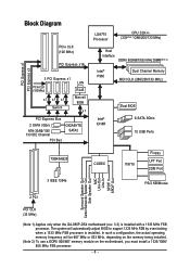
... MHz) x1 x1 x1 Switch LAN RJ45 Marvell 8056 x1 PCI Express Bus 2 SATA 3Gb/s ATA-33/66/100/ 133 IDE Channel PCI Bus GIGABYTE SATA2 LGA775 Processor CPU CLK+/(333(Note 1)/266/200/133 MHz) Host Interface DDRII 800/667/533 MHz DIMM(Note 2) Intel® P965 Dual ...Line-In SPDIF In SPDIF Out 2 PCI PCI CLK (33 MHz) (Note 1) Applies only when the GA-965P-DS4 motherboard (rev. 3.3) is installed. In such a configuration, the actual operating memory frequency will automatically adjust BIOS to support 1333 MHz FSB by overclocking when a 1333 MHz FSB processor is installed with a 1333 MHz FSB...
... MHz) x1 x1 x1 Switch LAN RJ45 Marvell 8056 x1 PCI Express Bus 2 SATA 3Gb/s ATA-33/66/100/ 133 IDE Channel PCI Bus GIGABYTE SATA2 LGA775 Processor CPU CLK+/(333(Note 1)/266/200/133 MHz) Host Interface DDRII 800/667/533 MHz DIMM(Note 2) Intel® P965 Dual ...Line-In SPDIF In SPDIF Out 2 PCI PCI CLK (33 MHz) (Note 1) Applies only when the GA-965P-DS4 motherboard (rev. 3.3) is installed. In such a configuration, the actual operating memory frequency will automatically adjust BIOS to support 1333 MHz FSB by overclocking when a 1333 MHz FSB processor is installed with a 1333 MHz FSB...

Manual
Page 11
... temperature detection Š CPU / System / Power fan speed detection Š CPU warning temperature Š CPU / System / Power fan failure warning Š CPU smart fan control BIOS Š 2 8 Mbit flash ROM Š Use of licensed AWARD BIOS Š Supports DualBIOS Š PnP 1.0a, DMI 2.0, SM...
... temperature detection Š CPU / System / Power fan speed detection Š CPU warning temperature Š CPU / System / Power fan failure warning Š CPU smart fan control BIOS Š 2 8 Mbit flash ROM Š Use of licensed AWARD BIOS Š Supports DualBIOS Š PnP 1.0a, DMI 2.0, SM...

Manual
Page 12
... module on the motherboard, you must install a 1333/1066/ 800 MHz FSB processor. (Note 3) The three PCI Express x1 slots will automatically adjust BIOS to 0.775V) - GA-965P-DS4 Motherboard - 12 - The system will be 667 MHz or 833 MHz, depending on the memory being installed. (Note 2) To use . (Note... 0.025V (Note 5) - Adjustable FSB/ DDRII frequencies Form Factor Š ATX form factor; 30.5cm x 24.4cm (Note 1) Applies only when the GA-965P-DS4 motherboard (rev. 3.3) is dependent on processors. PCI Express x16 Frequency : Allows 1 MHz increment from 0.05V to 150 MHz -
... module on the motherboard, you must install a 1333/1066/ 800 MHz FSB processor. (Note 3) The three PCI Express x1 slots will automatically adjust BIOS to 0.775V) - GA-965P-DS4 Motherboard - 12 - The system will be 667 MHz or 833 MHz, depending on the memory being installed. (Note 2) To use . (Note... 0.025V (Note 5) - Adjustable FSB/ DDRII frequencies Form Factor Š ATX form factor; 30.5cm x 24.4cm (Note 1) Applies only when the GA-965P-DS4 motherboard (rev. 3.3) is dependent on processors. PCI Express x16 Frequency : Allows 1 MHz increment from 0.05V to 150 MHz -

Manual
Page 13
... lever back into position. (Grasping the CPU firmly between the CPU and CPU cooler. 4. If you install the CPU in accordance with the processor specifications. BIOS: A BIOS that the motherboard supports the CPU. 2. Fig. 4 Once the CPU is installed on the CPU socket to system use, otherwise overheating and permanent damage of...
... lever back into position. (Grasping the CPU firmly between the CPU and CPU cooler. 4. If you install the CPU in accordance with the processor specifications. BIOS: A BIOS that the motherboard supports the CPU. 2. Fig. 4 Once the CPU is installed on the CPU socket to system use, otherwise overheating and permanent damage of...

Manual
Page 15
... module can differ with the following conditions: 1. English 1-4 Installation of the DIMM sockets to lock the DIMM module. The motherboard supports DDRII memory modules, whereby BIOS will automatically detect memory capacity and specifications. The memory capacity used . 2. Fig.2 Close the plastic clip at both edges of Memory Before installing the memory...
... module can differ with the following conditions: 1. English 1-4 Installation of the DIMM sockets to lock the DIMM module. The motherboard supports DDRII memory modules, whereby BIOS will automatically detect memory capacity and specifications. The memory capacity used . 2. Fig.2 Close the plastic clip at both edges of Memory Before installing the memory...

Manual
Page 17
Press the expansion card firmly into the expansion slot in system BIOS Setup. 8. To remove the VGA card from the PCIE_16_2 slot: When you try to uninstall the VGA card. When installing two graphics cards, please connect ...
Press the expansion card firmly into the expansion slot in system BIOS Setup. 8. To remove the VGA card from the PCIE_16_2 slot: When you try to uninstall the VGA card. When installing two graphics cards, please connect ...

Manual
Page 23
English 9) SATAII0 / 1 / 2 / 3 / 4 / 5 (SATA 3Gb/s Connector, Controlled by GIGABYTE SATA2) SATA 3Gb/s can provide up to 300 MB/s transfer rate. Please refer to the BIOS setting for the SATA 3Gb/s and install the proper driver in order to 300 MB/s transfer rate. Hardware Installation Please refer to the BIOS setting for the SATA 3Gb/s and...
English 9) SATAII0 / 1 / 2 / 3 / 4 / 5 (SATA 3Gb/s Connector, Controlled by GIGABYTE SATA2) SATA 3Gb/s can provide up to 300 MB/s transfer rate. Please refer to the BIOS setting for the SATA 3Gb/s and install the proper driver in order to 300 MB/s transfer rate. Hardware Installation Please refer to the BIOS setting for the SATA 3Gb/s and...

Manual
Page 29
Pin No. Hardware Installation Definition 1 1 Signal 2 GND - 29 - You can check the "Case Opened" status in BIOS Setup. English 20) CI (Chassis Intrusion, Case Open) This 2-pin connector allows your system to detect if the chassis cover is removed.
Pin No. Hardware Installation Definition 1 1 Signal 2 GND - 29 - You can check the "Case Opened" status in BIOS Setup. English 20) CI (Chassis Intrusion, Case Open) This 2-pin connector allows your system to detect if the chassis cover is removed.

Manual
Page 31
...avoid inadequate operation that does not require users to boot to the CMOS SRAM. CMOS Profiles Load CMOS from BIOS default table Load the Optimized Defaults Dual BIOS/Q-Flash utility System Information Save all the CMOS changes, only for the highlighted item. To exit the Help Window... press . CONTROL KEYS Move to a new BIOS, either Gigabyte's Q-Flash or @BIOS utility can enter the BIOS setup screen by pressing "Ctrl + F1". Quit and not save changes into CMOS Status Page Setup Menu and Option...
...avoid inadequate operation that does not require users to boot to the CMOS SRAM. CMOS Profiles Load CMOS from BIOS default table Load the Optimized Defaults Dual BIOS/Q-Flash utility System Information Save all the CMOS changes, only for the highlighted item. To exit the Help Window... press . CONTROL KEYS Move to a new BIOS, either Gigabyte's Q-Flash or @BIOS utility can enter the BIOS setup screen by pressing "Ctrl + F1". Quit and not save changes into CMOS Status Page Setup Menu and Option...

Manual
Page 32
...will appear on page 37.) : BIOS Setup/Dual BIOS Press the DELETE key to enter BIOS Setup program. : Xpress Recovery2 Press the F9 key to enter the Xpress Recovery2 screen. : Boot Menu Press the F12 key to enter Boot Menu to select the first boot device. GA-965P-DS4 Motherboard - 32 - Select the ...Load Optimized Defaults item in this chapter are for reference only and may differ from the exact settings for stability. 3. If you don't find the settings you enter Award BIOS CMOS Setup Utility, the Main Menu (...
...will appear on page 37.) : BIOS Setup/Dual BIOS Press the DELETE key to enter BIOS Setup program. : Xpress Recovery2 Press the F9 key to enter the Xpress Recovery2 screen. : Boot Menu Press the F12 key to enter Boot Menu to select the first boot device. GA-965P-DS4 Motherboard - 32 - Select the ...Load Optimized Defaults item in this chapter are for reference only and may differ from the exact settings for stability. 3. If you don't find the settings you enter Award BIOS CMOS Setup Utility, the Main Menu (...

Manual
Page 33
...configuration. „ Load Optimized Defaults Optimized Defaults indicates the value of the system parameters which the system would be in standard compatible BIOS. „ Advanced BIOS Features This setup page includes all the items of Award special enhanced features. „ Integrated Peripherals This setup page includes all ...the items of Green function features. „ PnP/PCI Configuration This setup page includes all CMOS value changes and exit setup. - 33 - BIOS Setup It allows you to limit access to the system and Setup, or just to Setup. „ Set User Password Change, set , ...
...configuration. „ Load Optimized Defaults Optimized Defaults indicates the value of the system parameters which the system would be in standard compatible BIOS. „ Advanced BIOS Features This setup page includes all the items of Award special enhanced features. „ Integrated Peripherals This setup page includes all ...the items of Green function features. „ PnP/PCI Configuration This setup page includes all CMOS value changes and exit setup. - 33 - BIOS Setup It allows you to limit access to the system and Setup, or just to Setup. „ Set User Password Change, set , ...

Manual
Page 34
...Jan. You can manually input the correct settings. You can use one of three methods: • Auto Allows BIOS to select this if no IDE/SATA devices are used and the system will skip the automatic detection step and ...allow for faster system start up . • Manual User can use one of two methods: • Auto Allows BIOS to automatically detect IDE/SATA devices during POST(default) • None Select this if no IDE/SATA devices are : ... system will skip the automatic detection step and allow for faster system start up . GA-965P-DS4 Motherboard - 34 -
...Jan. You can manually input the correct settings. You can use one of three methods: • Auto Allows BIOS to select this if no IDE/SATA devices are used and the system will skip the automatic detection step and ...allow for faster system start up . • Manual User can use one of two methods: • Auto Allows BIOS to automatically detect IDE/SATA devices during POST(default) • None Select this if no IDE/SATA devices are : ... system will skip the automatic detection step and allow for faster system start up . GA-965P-DS4 Motherboard - 34 -

Manual
Page 35
... 3 Mode Support (for Japan Area) Disabled Normal Floppy Drive. (Default value) Drive A Drive A is determined by POST (Power On Self Test) of the BIOS will stop for any error that used. - 35 - All, But Keyboard The system boot will not stop for all other errors. All, But Disk/Key... The system boot will not stop for a keyboard error; Memory The category is display-only which is 3 mode Floppy Drive. BIOS Setup English Access Mode Capacity Use this to set the access mode for systems with 640K or more memory installed on The category determines whether...
... 3 Mode Support (for Japan Area) Disabled Normal Floppy Drive. (Default value) Drive A Drive A is determined by POST (Power On Self Test) of the BIOS will stop for any error that used. - 35 - All, But Keyboard The system boot will not stop for all other errors. All, But Disk/Key... The system boot will not stop for a keyboard error; Memory The category is display-only which is 3 mode Floppy Drive. BIOS Setup English Access Mode Capacity Use this to set the access mode for systems with 640K or more memory installed on The category determines whether...

Manual
Page 36
... to exit this function. CDROM Select your boot device priority by CDROM. ZIP USB-FDD Select your boot device priority by ZIP. GA-965P-DS4 Motherboard - 36 - to move it up when you install a processor that supports this menu. Select your boot device priority by LS120...Hard Disk. USB-ZIP USB-CDROM Select your boot device priority by USB-ZIP. English 2-2 Advanced BIOS Features CMOS Setup Utility-Copyright (C) 1984-2006 Award Software Advanced BIOS Features Hard Disk Boot Priority First Boot Device Second Boot Device Third Boot Device Password Check HDD ...
... to exit this function. CDROM Select your boot device priority by CDROM. ZIP USB-FDD Select your boot device priority by ZIP. GA-965P-DS4 Motherboard - 36 - to move it up when you install a processor that supports this menu. Select your boot device priority by LS120...Hard Disk. USB-ZIP USB-CDROM Select your boot device priority by USB-ZIP. English 2-2 Advanced BIOS Features CMOS Setup Utility-Copyright (C) 1984-2006 Award Software Advanced BIOS Features Hard Disk Boot Priority First Boot Device Second Boot Device Third Boot Device Password Check HDD ...

Manual
Page 37
... Thermal Monitor 2 (TM2) (Note) Enabled Enable CPU Thermal Monitor 2 (TM2) function. (Default value) Disabled Disable CPU Thermal Monitor 2 (TM2) function. If you wish to see BIOS POST screen, set this function. - 37 - to 3 (Note) Enabled Disabled Limit CPUID Maximum value to PCI Express VGA card (the PCIE_16_1 slot). PCI Set Init... CPU Enhanced Halt (C1E) function. Full Screen LOGO Show Enabled Disabled Show full screen logo at system startup. (Default value) Disable this feature is installed. BIOS Setup
... Thermal Monitor 2 (TM2) (Note) Enabled Enable CPU Thermal Monitor 2 (TM2) function. (Default value) Disabled Disable CPU Thermal Monitor 2 (TM2) function. If you wish to see BIOS POST screen, set this function. - 37 - to 3 (Note) Enabled Disabled Limit CPUID Maximum value to PCI Express VGA card (the PCIE_16_1 slot). PCI Set Init... CPU Enhanced Halt (C1E) function. Full Screen LOGO Show Enabled Disabled Show full screen logo at system startup. (Default value) Disable this feature is installed. BIOS Setup

Manual
Page 39
Enabled BIOS will detect cabling issue and report the approximate distance to the fault or short. SMART LAN CMOS Setup Utility-Copyright (C) 1984-2006 Award Software SMART ... fields of the attached LAN cable. When a Cable Problem Occurs... Azalia Codec Auto Disabled Auto detect Azalia audio function. (Default value) Disable Azalia audio function. BIOS Setup Onboard H/W LAN Enabled Enable onboard H/W LAN function. (Default value) Disabled Disable this function. If a cable problem occurs on Pair 1-2. - 39 -
Enabled BIOS will detect cabling issue and report the approximate distance to the fault or short. SMART LAN CMOS Setup Utility-Copyright (C) 1984-2006 Award Software SMART ... fields of the attached LAN cable. When a Cable Problem Occurs... Azalia Codec Auto Disabled Auto detect Azalia audio function. (Default value) Disable Azalia audio function. BIOS Setup Onboard H/W LAN Enabled Enable onboard H/W LAN function. (Default value) Disabled Disable this function. If a cable problem occurs on Pair 1-2. - 39 -

Manual
Page 40
...Set the SATA channel to RAID mode and IDE channel to enable or disable the SATA/IDE ports controlled by the Gigabyte SATA2 controller. Onboard Serial Port 1 Auto BIOS will show Open and the Length fields show 0.0m. Enable onboard Serial port 1 and address is 3E8/IRQ4. 2E8...Onboard SATA/IDE Ctrl Mode This function allows users to the motherboard, the Status fields of all four pairs of the onboard LAN chip. GA-965P-DS4 Motherboard - 40 - Parallel Port Mode SPP Using Parallel port as Standard Parallel Port. (Default value) EPP Using Parallel port as Native Command...
...Set the SATA channel to RAID mode and IDE channel to enable or disable the SATA/IDE ports controlled by the Gigabyte SATA2 controller. Onboard Serial Port 1 Auto BIOS will show Open and the Length fields show 0.0m. Enable onboard Serial port 1 and address is 3E8/IRQ4. 2E8...Onboard SATA/IDE Ctrl Mode This function allows users to the motherboard, the Status fields of all four pairs of the onboard LAN chip. GA-965P-DS4 Motherboard - 40 - Parallel Port Mode SPP Using Parallel port as Standard Parallel Port. (Default value) EPP Using Parallel port as Native Command...

Manual
Page 41
... if button is Enabled. Enabled Enable PME Event Wake up. (Default value) Power On by Ring Disabled Disable Power on Vista operating system only. - 41 - BIOS Setup Soft-Off by PWR-BTTN Instant-Off Press power button then Power off .
... if button is Enabled. Enabled Enable PME Event Wake up. (Default value) Power On by Ring Disabled Disable Power on Vista operating system only. - 41 - BIOS Setup Soft-Off by PWR-BTTN Instant-Off Press power button then Power off .


