Manual
Page 1
GA-965GM-DS2 / GA-965GM-S2 Intel® CoreTM 2 Extreme quad-core / CoreTM 2 Quad / Intel® CoreTM 2 Extreme dual-core / CoreTM 2 Duo / Intel® Pentium® Processor Extreme Edition / Intel® Pentium® D / Pentium® 4 LGA775 Processor Motherboard User's Manual Rev. 2031 12ME-965GMDR-2031R * The WEEE marking on the product indicates this product must not be...
GA-965GM-DS2 / GA-965GM-S2 Intel® CoreTM 2 Extreme quad-core / CoreTM 2 Quad / Intel® CoreTM 2 Extreme dual-core / CoreTM 2 Duo / Intel® Pentium® Processor Extreme Edition / Intel® Pentium® D / Pentium® 4 LGA775 Processor Motherboard User's Manual Rev. 2031 12ME-965GMDR-2031R * The WEEE marking on the product indicates this product must not be...
Manual
Page 2
Motherboard GA-965GM-DS2 / GA-965GM-S2 Oct. 1, 2006 Motherboard GA-965GM-DS2 / GA-965GM-S2 Oct. 1, 2006
Motherboard GA-965GM-DS2 / GA-965GM-S2 Oct. 1, 2006 Motherboard GA-965GM-DS2 / GA-965GM-S2 Oct. 1, 2006
Manual
Page 4
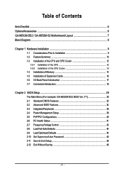
Table of Contents ItemChecklist ...6 OptionalAccessories ...6 GA-965GM-DS2 / GA-965GM-S2 Motherboard Layout 7 Block Diagram ...8 Chapter 1 Hardware Installation 9 1-1 Considerations Prior to Installation 9 1-2 Feature Summary 10 1-3 Installation of the CPU...1-5 Installation of Expansion Cards 16 1-6 I/O Back Panel Introduction 17 1-7 Connectors Introduction 18 Chapter 2 BIOS Setup 29 The Main Menu (For example: GA-965GM-DS2 BIOS Ver.: F1 30 2-1 Standard CMOS Features 32 2-2 Advanced BIOS Features 34 2-3 IntegratedPeripherals 36 2-4 Power Management Setup 39 2-5 PnP/PCI ...
Table of Contents ItemChecklist ...6 OptionalAccessories ...6 GA-965GM-DS2 / GA-965GM-S2 Motherboard Layout 7 Block Diagram ...8 Chapter 1 Hardware Installation 9 1-1 Considerations Prior to Installation 9 1-2 Feature Summary 10 1-3 Installation of the CPU...1-5 Installation of Expansion Cards 16 1-6 I/O Back Panel Introduction 17 1-7 Connectors Introduction 18 Chapter 2 BIOS Setup 29 The Main Menu (For example: GA-965GM-DS2 BIOS Ver.: F1 30 2-1 Standard CMOS Features 32 2-2 Advanced BIOS Features 34 2-3 IntegratedPeripherals 36 2-4 Power Management Setup 39 2-5 PnP/PCI ...
Manual
Page 7
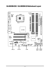
GA-965GM-DS2 / GA-965GM-S2 Motherboard Layout KB_MS ATX_12V LGA775 CPU_FAN ATX FDD IT8718 COMA GA-965GM-DS2 / GA-965GM-S2 DDRII1 LPT VGA USB_1394 USB_LAN Intel® G965 AUDIO F_AUDIO Marvell 88E8056 PCIE_16 PCI1 BIOS PCI2 Intel® ICH8 IDE GIGABYTE SATA2 CD_IN CODEC PCIE_1 CI CLR_CMOS BATTERY COMB F1_1394 F2_1394 F_USB2 F_USB3 SATAII2 SATAII3 SPDIF_IO SYS _FAN F_USB1 SATAII0 GSATAII0 SATAII1 GSATAII1 DDRII2 DDRII3 DDRII4 PWR_LED F_PANEL - 7 -
GA-965GM-DS2 / GA-965GM-S2 Motherboard Layout KB_MS ATX_12V LGA775 CPU_FAN ATX FDD IT8718 COMA GA-965GM-DS2 / GA-965GM-S2 DDRII1 LPT VGA USB_1394 USB_LAN Intel® G965 AUDIO F_AUDIO Marvell 88E8056 PCIE_16 PCI1 BIOS PCI2 Intel® ICH8 IDE GIGABYTE SATA2 CD_IN CODEC PCIE_1 CI CLR_CMOS BATTERY COMB F1_1394 F2_1394 F_USB2 F_USB3 SATAII2 SATAII3 SPDIF_IO SYS _FAN F_USB1 SATAII0 GSATAII0 SATAII1 GSATAII1 DDRII2 DDRII3 DDRII4 PWR_LED F_PANEL - 7 -

Manual
Page 8
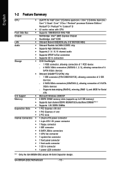
... CLK (100 MHz) LGA775 Processor CPU CLK+/-(266/200/133 MHz) VGA PCI Express x16 2 SATA 3Gb/s LAN ATA-33/66/100/133 IDE Channel GIGABYTE RJ45 Marvell SATA2 88E8056 PCI Express Bus x 1 x1 x1 PCIe CLK (100 MHz) 1 PCI Express x1 PCI Bus TSB43AB23 Host Interface DDRII 800/667/533... Line-In SPDIF In SPDIF Out 2 PCI PCI CLK(33 MHz) 10 USB Ports (Note) To use a DDR II 800/667 memory module on the motherboard, you must install an 1066/ 800 MHz FSB processor. - 8 -
... CLK (100 MHz) LGA775 Processor CPU CLK+/-(266/200/133 MHz) VGA PCI Express x16 2 SATA 3Gb/s LAN ATA-33/66/100/133 IDE Channel GIGABYTE RJ45 Marvell SATA2 88E8056 PCI Express Bus x 1 x1 x1 PCIe CLK (100 MHz) 1 PCI Express x1 PCI Bus TSB43AB23 Host Interface DDRII 800/667/533... Line-In SPDIF In SPDIF Out 2 PCI PCI CLK(33 MHz) 10 USB Ports (Note) To use a DDR II 800/667 memory module on the motherboard, you must install an 1066/ 800 MHz FSB processor. - 8 -

Manual
Page 9
... do not remove the stickers on an uneven surface. 7. Prior to be an unofficial Gigabyte product. - 9 - English Chapter 1 Hardware Installation 1-1 Considerations Prior to Installation Preparing Your Computer The motherboard contains numerous delicate electronic circuits and components which can lead to damage to system components as well as physical harm to the user...
... do not remove the stickers on an uneven surface. 7. Prior to be an unofficial Gigabyte product. - 9 - English Chapter 1 Hardware Installation 1-1 Considerations Prior to Installation Preparing Your Computer The motherboard contains numerous delicate electronic circuits and components which can lead to damage to system components as well as physical harm to the user...
Manual
Page 10
GA-965GM-(D)S2 Motherboard - 10 - Supports data striping (RAID 0), mirroring (RAID 1), and JBOD for Intel® CoreTM 2 Extreme quad-core / CoreTM 2 Extreme dual-core / CoreTM 2 Quad / CoreTM 2 Duo /... Storage Š ICH8 Southbrigde - 1 FDD connector, allowing connection of 1 FDD device - 4 SATA 3Gb/s connectors (SATAII0,1, 2, 3), allowing connection of 4 SATA 3Gb/s devices Š Onboard GIGABYTE SATA2 chip - 1 IDE connector (ATA-33/66/100/133), allowing connection of 2 IDE devices - 2 SATA 3Gb/s connectors (GSATAII0,1), allowing connection of 2 SATA 3Gb/s devices - English...
GA-965GM-(D)S2 Motherboard - 10 - Supports data striping (RAID 0), mirroring (RAID 1), and JBOD for Intel® CoreTM 2 Extreme quad-core / CoreTM 2 Extreme dual-core / CoreTM 2 Quad / CoreTM 2 Duo /... Storage Š ICH8 Southbrigde - 1 FDD connector, allowing connection of 1 FDD device - 4 SATA 3Gb/s connectors (SATAII0,1, 2, 3), allowing connection of 4 SATA 3Gb/s devices Š Onboard GIGABYTE SATA2 chip - 1 IDE connector (ATA-33/66/100/133), allowing connection of 2 IDE devices - 2 SATA 3Gb/s connectors (GSATAII0,1), allowing connection of 2 SATA 3Gb/s devices - English...

Manual
Page 11
... Security (OEM version) Form Factor Š Micro ATX form factor; 24.4cm x 24.4cm (Note 1) To use a DDR II 800/667 memory module on the motherboard, you must install an 1066/ 800 MHz FSB processor. (Note 2) EasyTune functions may vary depending on different...
... Security (OEM version) Form Factor Š Micro ATX form factor; 24.4cm x 24.4cm (Note 1) To use a DDR II 800/667 memory module on the motherboard, you must install an 1066/ 800 MHz FSB processor. (Note 2) EasyTune functions may vary depending on different...

Manual
Page 12
... HT Technology and has it enabled - Fig. 4 Once the CPU is installed on the CPU socket to the CPU during installation.) GA-965GM-(D)S2 Motherboard - 12 - HT functionality requirement content : Enabling the functionality of Hyper-Threading Technology for your thumb and forefinger, carefully place it does... so according to system use, otherwise overheating and permanent damage of the CPU may occur. 5. It is not recommended that the motherboard supports the CPU. 2. Please make sure the heatsink is properly inserted, please replace the plastic covering and push the metal lever ...
... HT Technology and has it enabled - Fig. 4 Once the CPU is installed on the CPU socket to the CPU during installation.) GA-965GM-(D)S2 Motherboard - 12 - HT functionality requirement content : Enabling the functionality of Hyper-Threading Technology for your thumb and forefinger, carefully place it does... so according to system use, otherwise overheating and permanent damage of the CPU may occur. 5. It is not recommended that the motherboard supports the CPU. 2. Please make sure the heatsink is properly inserted, please replace the plastic covering and push the metal lever ...

Manual
Page 13
Hardware Installation Fig. 6 Finally, please attach the power connector of motherboard after installing. Fig. 2 (Turning the push pin along the direction of arrow is to remove ... manual) Fig. 5 Please check the back of the CPU cooler to the pin hole on the motherboard.Pressing down the push pins diagonally. Fig. 4 Please make sure the push pins aim to the CPU fan header located ...on the motherboard. To prevent such an occurrence, it is only for Intel boxed fan) Fig. 3 Place the CPU cooler atop...
Hardware Installation Fig. 6 Finally, please attach the power connector of motherboard after installing. Fig. 2 (Turning the push pin along the direction of arrow is to remove ... manual) Fig. 5 Please check the back of the CPU cooler to the pin hole on the motherboard.Pressing down the push pins diagonally. Fig. 4 Please make sure the push pins aim to the CPU fan header located ...on the motherboard. To prevent such an occurrence, it is only for Intel boxed fan) Fig. 3 Place the CPU cooler atop...

Manual
Page 14
Memory modules have a foolproof insertion design. The motherboard supports DDRII memory modules, whereby BIOS will automatically detect memory capacity and specifications. Memory modules are unable to prevent hardware damage. 3. The memory capacity used . 2. ... with the following conditions: 1. Then push it down. Before installing or removing memory modules, please make sure that the computer power is supported by the motherboard. Fig.2 Close the plastic clip at both edges of the DIMM sockets to remove the DIMM module. GA-965GM-(D)S2 Motherboard - 14 -
Memory modules have a foolproof insertion design. The motherboard supports DDRII memory modules, whereby BIOS will automatically detect memory capacity and specifications. Memory modules are unable to prevent hardware damage. 3. The memory capacity used . 2. ... with the following conditions: 1. Then push it down. Before installing or removing memory modules, please make sure that the computer power is supported by the motherboard. Fig.2 Close the plastic clip at both edges of the DIMM sockets to remove the DIMM module. GA-965GM-(D)S2 Motherboard - 14 -

Manual
Page 16
Make sure your computer's chassis cover, screws and slot bracket from BIOS. 8. GA-965GM-(D)S2 Motherboard - 16 - Remove your VGA card is locked by following the steps outlined below: 1. English 1-5 Installation of Expansion Cards You can also press the latch on ... the computer. 3. Please align the VGA card to the onboard PCI Express x16 slot and press firmly down on the card are indeed seated in motherboard. 4. Read the related expansion card's instruction document before install the expansion card into expansion slot in the slot. 5. To install a VGA card or to ...
Make sure your computer's chassis cover, screws and slot bracket from BIOS. 8. GA-965GM-(D)S2 Motherboard - 16 - Remove your VGA card is locked by following the steps outlined below: 1. English 1-5 Installation of Expansion Cards You can also press the latch on ... the computer. 3. Please align the VGA card to the onboard PCI Express x16 slot and press firmly down on the card are indeed seated in motherboard. 4. Read the related expansion card's instruction document before install the expansion card into expansion slot in the slot. 5. To install a VGA card or to ...

Manual
Page 18
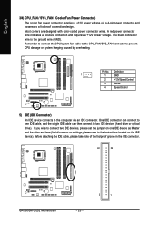
... 15 19 14 78 11) F_AUDIO 12) CD_IN 13) SPDIF_IO 14) F_USB1 / F_USB2 / F_USB3 15) F1_1394 / F2_1394 16) COMB 17) CI 18) CLR_CMOS 19) BATTERY GA-965GM-(D)S2 Motherboard - 18 - Stereo speakers, earphone or front surround speakers can be connected to the 2-/4-/6-/8-
... 15 19 14 78 11) F_AUDIO 12) CD_IN 13) SPDIF_IO 14) F_USB1 / F_USB2 / F_USB3 15) F1_1394 / F2_1394 16) COMB 17) CI 18) CLR_CMOS 19) BATTERY GA-965GM-(D)S2 Motherboard - 18 - Stereo speakers, earphone or front surround speakers can be connected to the 2-/4-/6-/8-
Manual
Page 19
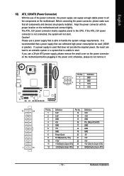
... power consumption be used (300W or greater). Align the power connector with its proper location on the motherboard before plugging in the power cord; If you use a power supply that all the components on the motherboard. Please use a 24-pin ATX power supply, please remove the small cover on the power connector...
... power consumption be used (300W or greater). Align the power connector with its proper location on the motherboard before plugging in the power cord; If you use a power supply that all the components on the motherboard. Please use a 24-pin ATX power supply, please remove the small cover on the power connector...
Manual
Page 20
... connector wire is the ground wire (GND). Before attaching the IDE cable, please take note of the foolproof groove in the IDE connector. 40 39 GA-965GM-(D)S2 Motherboard - 20 - 2 1 Pin No.
... connector wire is the ground wire (GND). Before attaching the IDE cable, please take note of the foolproof groove in the IDE connector. 40 39 GA-965GM-(D)S2 Motherboard - 20 - 2 1 Pin No.
Manual
Page 22
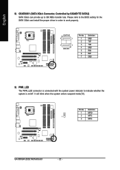
It will blink when the system enters suspend mode(S1). GA-965GM-(D)S2 Motherboard - 22 - English 8) GSATAII0/1 (SATA 3Gb/s Connector, Controlled by GIGABYTE SATA2) SATA 3Gb/s can provide up to work properly. Please refer to the BIOS setting for the SATA 3Gb/s and install the proper driver in ...
It will blink when the system enters suspend mode(S1). GA-965GM-(D)S2 Motherboard - 22 - English 8) GSATAII0/1 (SATA 3Gb/s Connector, Controlled by GIGABYTE SATA2) SATA 3Gb/s can provide up to work properly. Please refer to the BIOS setting for the SATA 3Gb/s and install the proper driver in ...

Manual
Page 24
... this connector. Incorrect connection between the module and connector will make the audio device unable to the instructions on Page 80 about the software settings. GA-965GM-(D)S2 Motherboard - 24 - For optional front panel audio module, please contact your chassis manufacturer. 10 9 2 1 HD Audio: Pin No. 1 2 3 4 5 6 7 8 9 10 Definition MIC2_L GND MIC2_R -ACZ_DET LINE2_R FSENSE1...
... this connector. Incorrect connection between the module and connector will make the audio device unable to the instructions on Page 80 about the software settings. GA-965GM-(D)S2 Motherboard - 24 - For optional front panel audio module, please contact your chassis manufacturer. 10 9 2 1 HD Audio: Pin No. 1 2 3 4 5 6 7 8 9 10 Definition MIC2_L GND MIC2_R -ACZ_DET LINE2_R FSENSE1...
Manual
Page 26
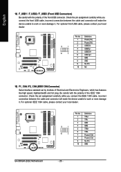
... optional front USB cable, please contact your local dealer. 9 1 10 2 Pin No. 1 2 3 4 5 6 7 8 9 10 Definition TPA+ TPAGND GND TPB+ TPBPower (12V) Power (12V) No Pin GND GA-965GM-(D)S2 Motherboard - 26 - Check the pin assignment carefully while you connect the IEEE 1394 cable, incorrect connection between the cable and connector will make the device unable...
... optional front USB cable, please contact your local dealer. 9 1 10 2 Pin No. 1 2 3 4 5 6 7 8 9 10 Definition TPA+ TPAGND GND TPB+ TPBPower (12V) Power (12V) No Pin GND GA-965GM-(D)S2 Motherboard - 26 - Check the pin assignment carefully while you connect the IEEE 1394 cable, incorrect connection between the cable and connector will make the device unable...
Manual
Page 28
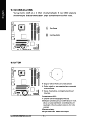
... CMOS) You may clear the CMOS data to erase CMOS... 1. Dispose of explosion if battery is incorrectly replaced. Open: Normal Short: Clear CMOS 19) BATTERY GA-965GM-(D)S2 Motherboard Danger of used batteries according to the manufacturer's instructions. To clear CMOS, temporarily short the two pins.
... CMOS) You may clear the CMOS data to erase CMOS... 1. Dispose of explosion if battery is incorrectly replaced. Open: Normal Short: Clear CMOS 19) BATTERY GA-965GM-(D)S2 Motherboard Danger of used batteries according to the manufacturer's instructions. To clear CMOS, temporarily short the two pins.
Manual
Page 29
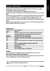
...not save changes into CMOS Status Page Setup Menu and Option Page Setup Menu - Because BIOS flashing is displayed at the bottom of the motherboard. CONTROL KEYS Enter> Move to the CMOS SRAM. Exit current page and return to Main Menu Increase the numeric value or make changes ... 2 BIOS Setup BIOS (Basic Input and Output System) includes a CMOS SETUP utility which allows user to configure required settings or to a new BIOS, either Gigabyte's Q-Flash or @BIOS utility can enter the BIOS setup screen by pressing "Ctrl + F1". If you to pop up a small help , only for...
...not save changes into CMOS Status Page Setup Menu and Option Page Setup Menu - Because BIOS flashing is displayed at the bottom of the motherboard. CONTROL KEYS Enter> Move to the CMOS SRAM. Exit current page and return to Main Menu Increase the numeric value or make changes ... 2 BIOS Setup BIOS (Basic Input and Output System) includes a CMOS SETUP utility which allows user to configure required settings or to a new BIOS, either Gigabyte's Q-Flash or @BIOS utility can enter the BIOS setup screen by pressing "Ctrl + F1". If you to pop up a small help , only for...


