Manual
Page 1
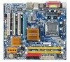
GA-945GCM-S2 GA-945GCMX-S2 Intel® CoreTM 2 Extreme dual-core / CoreTM 2 Duo / Intel® Pentium® D / Pentium® 4 / Celeron® D LGA775 Processor Motherboard User's Manual Rev. 6602 12ME-945CMX2R-6602R * The WEEE marking on the product indicates this product must not be disposed of with user's other household waste and must be handed over to a designated collection point for the recycling of waste electrical and electronic equipment!! * The WEEE marking applies only in European Union's member states.
GA-945GCM-S2 GA-945GCMX-S2 Intel® CoreTM 2 Extreme dual-core / CoreTM 2 Duo / Intel® Pentium® D / Pentium® 4 / Celeron® D LGA775 Processor Motherboard User's Manual Rev. 6602 12ME-945CMX2R-6602R * The WEEE marking on the product indicates this product must not be disposed of with user's other household waste and must be handed over to a designated collection point for the recycling of waste electrical and electronic equipment!! * The WEEE marking applies only in European Union's member states.

Manual
Page 2
Motherboard GA-945GCMX-S2 Mar. 23, 2007 Motherboard GA-945GCMX-S2 Mar. 23, 2007
Motherboard GA-945GCMX-S2 Mar. 23, 2007 Motherboard GA-945GCMX-S2 Mar. 23, 2007
Manual
Page 3
Motherboard GA-945GCM-S2 Jan. 12, 2007 Motherboard GA-945GCM-S2 Jan. 12, 2007
Motherboard GA-945GCM-S2 Jan. 12, 2007 Motherboard GA-945GCM-S2 Jan. 12, 2007
Manual
Page 5
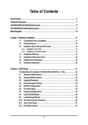
Table of Contents ItemChecklist ...7 OptionalAccessories ...7 GA-945GCMX-S2 Motherboard Layout 8 GA-945GCM-S2 Motherboard Layout 9 Block Diagram ...10 Chapter 1 Hardware Installation 11 1-1 Considerations Prior to Installation 11 1-2 Feature Summary 12 1-3 ...1-5 Installation of Expansion Cards 18 1-6 I/O Back Panel Introduction 19 1-7 Connectors Introduction 20 Chapter 2 BIOS Setup 31 The Main Menu (For example: GA-945GCMX-S2 BIOS Ver. : F5a 32 2-1 Standard CMOS Features 34 2-2 Advanced BIOS Features 36 2-3 IntegratedPeripherals 38 2-4 Power Management Setup 42 2-5 PnP/PCI ...
Table of Contents ItemChecklist ...7 OptionalAccessories ...7 GA-945GCMX-S2 Motherboard Layout 8 GA-945GCM-S2 Motherboard Layout 9 Block Diagram ...10 Chapter 1 Hardware Installation 11 1-1 Considerations Prior to Installation 11 1-2 Feature Summary 12 1-3 ...1-5 Installation of Expansion Cards 18 1-6 I/O Back Panel Introduction 19 1-7 Connectors Introduction 20 Chapter 2 BIOS Setup 31 The Main Menu (For example: GA-945GCMX-S2 BIOS Ver. : F5a 32 2-1 Standard CMOS Features 34 2-2 Advanced BIOS Features 36 2-3 IntegratedPeripherals 38 2-4 Power Management Setup 42 2-5 PnP/PCI ...

Manual
Page 8
GA-945GCMX-S2 Motherboard Layout KB_MS ATX_12V CPU_FAN LGA775 IT8718 COMA LPT VGA GA-945GCMX-S2 ATX R_USB LAN USB AUDIO SYS_FAN F_AUDIO Intel® 945 DDRII1 DDRII2 IDE FDD PCIE_16 RTL8110SC PCI1 SATAII0 SATAII2 SATAII1 SATAII3 PCI2 Intel® ICH7 PCIE_4 BIOS CODEC CD_IN COMB SPDIF_IO F_USB1 F_USB2 BATTERY CLR_CMOS CI PWR_LED F_PANEL - 8 -
GA-945GCMX-S2 Motherboard Layout KB_MS ATX_12V CPU_FAN LGA775 IT8718 COMA LPT VGA GA-945GCMX-S2 ATX R_USB LAN USB AUDIO SYS_FAN F_AUDIO Intel® 945 DDRII1 DDRII2 IDE FDD PCIE_16 RTL8110SC PCI1 SATAII0 SATAII2 SATAII1 SATAII3 PCI2 Intel® ICH7 PCIE_4 BIOS CODEC CD_IN COMB SPDIF_IO F_USB1 F_USB2 BATTERY CLR_CMOS CI PWR_LED F_PANEL - 8 -
Manual
Page 9
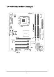
GA-945GCM-S2 Motherboard Layout KB_MS ATX_12V CPU_FAN LGA775 IT8718 COMA LPT VGA GA-945GCM-S2 ATX R_USB LAN USB AUDIO SYS_FAN F_AUDIO PCIE_16 RTL8110SC CODEC CD_IN COMB SPDIF_IO Intel® 945 DDRII1 DDRII2 IDE FDD PCI1 SATAII0 SATAII2 SATAII1 SATAII3 PCI2 Intel® ICH7 PCI3 BIOS F_USB1 F_USB2 BATTERY CLR_CMOS CI PWR_LED F_PANEL - 9 -
GA-945GCM-S2 Motherboard Layout KB_MS ATX_12V CPU_FAN LGA775 IT8718 COMA LPT VGA GA-945GCM-S2 ATX R_USB LAN USB AUDIO SYS_FAN F_AUDIO PCIE_16 RTL8110SC CODEC CD_IN COMB SPDIF_IO Intel® 945 DDRII1 DDRII2 IDE FDD PCI1 SATAII0 SATAII2 SATAII1 SATAII3 PCI2 Intel® ICH7 PCI3 BIOS F_USB1 F_USB2 BATTERY CLR_CMOS CI PWR_LED F_PANEL - 9 -

Manual
Page 11
... required for warranty validation. 2. Damage as physical harm to come in the user manual. 3. Damage due to be an unofficial Gigabyte product. - 11 - Installation Notices 1. Thus, prior to improper installation. 4. Damage due to installation, please follow the instructions below...: 1. Prior to installing the electronic components, please have a problem related to Installation Preparing Your Computer The motherboard contains numerous delicate electronic circuits and components which can lead to damage to system components as well as a result ...
... required for warranty validation. 2. Damage as physical harm to come in the user manual. 3. Damage due to be an unofficial Gigabyte product. - 11 - Installation Notices 1. Thus, prior to improper installation. 4. Damage due to installation, please follow the instructions below...: 1. Prior to installing the electronic components, please have a problem related to Installation Preparing Your Computer The motherboard contains numerous delicate electronic circuits and components which can lead to damage to system components as well as a result ...
Manual
Page 12
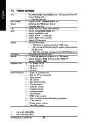
...; 1 S/PDIF In/Out connector Š 2 USB 2.0/1.1 connectors for additional 4 ports by cables Š 1 COMB connector Š 1 Chassis Intrusion connector Š 1 power LED connector Only for GA-945GCM-S2. Only for GA-945GCMX-S2. GA-945GCM(X)-S2 Motherboard - 12 -
...; 1 S/PDIF In/Out connector Š 2 USB 2.0/1.1 connectors for additional 4 ports by cables Š 1 COMB connector Š 1 Chassis Intrusion connector Š 1 power LED connector Only for GA-945GCM-S2. Only for GA-945GCMX-S2. GA-945GCM(X)-S2 Motherboard - 12 -

Manual
Page 13
... of a 1066/800 MHz FSB CPU is required if you wish to install DDR2 667 MHz memory. (Note 3) EasyTune functions may vary depending on different motherboards. - 13 - Hardware Installation
... of a 1066/800 MHz FSB CPU is required if you wish to install DDR2 667 MHz memory. (Note 3) EasyTune functions may vary depending on different motherboards. - 13 - Hardware Installation
Manual
Page 14
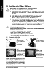
... upright position. Please take note of the one indented corner of the CPU. 3. It is installed on the CPU socket to the CPU during installation.) GA-945GCM(X)-S2 Motherboard - 14 - Chipset: An Intel® Chipset that the system bus frequency be set the frequency beyond hardware specifications since it enabled - If this occurs, ...a straight and downwards motion. HT functionality requirement content : Enabling the functionality of Hyper-Threading Technology for the peripherals. Avoid twisting or bending motions that the motherboard supports the CPU. 2.
... upright position. Please take note of the one indented corner of the CPU. 3. It is installed on the CPU socket to the CPU during installation.) GA-945GCM(X)-S2 Motherboard - 14 - Chipset: An Intel® Chipset that the system bus frequency be set the frequency beyond hardware specifications since it enabled - If this occurs, ...a straight and downwards motion. HT functionality requirement content : Enabling the functionality of Hyper-Threading Technology for the peripherals. Avoid twisting or bending motions that the motherboard supports the CPU. 2.
Manual
Page 15
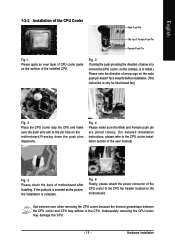
... is only for detailed installation instructions, please refer to the CPU cooler installation section of the user manual) Fig. 5 Please check the back of motherboard after installing. Fig. 2 (Turning the push pin along the direction of arrow sign on the male push pin doesn't face inwards before installation. ... Push Pin Fig.1 Please apply an even layer of CPU cooler paste on the surface of the CPU cooler to the pin hole on the motherboard.Pressing down the push pins diagonally. Fig. 4 Please make sure the Male and Female push pin are joined closely. (for Intel boxed fan) ...
... is only for detailed installation instructions, please refer to the CPU cooler installation section of the user manual) Fig. 5 Please check the back of motherboard after installing. Fig. 2 (Turning the push pin along the direction of arrow sign on the male push pin doesn't face inwards before installation. ... Push Pin Fig.1 Please apply an even layer of CPU cooler paste on the surface of the CPU cooler to the pin hole on the motherboard.Pressing down the push pins diagonally. Fig. 4 Please make sure the Male and Female push pin are joined closely. (for Intel boxed fan) ...
Manual
Page 16
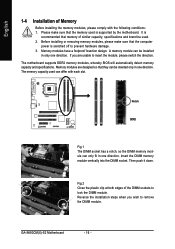
... the plastic clip at both edges of similar capacity, specifications and brand be installed in one direction. Then push it down. GA-945GCM(X)-S2 Motherboard - 16 - Reverse the installation steps when you are designed so that the memory used can only fit in only one direction. The... motherboard supports DDR2 memory modules, whereby BIOS will automatically detect memory capacity and specifications. The memory capacity used is switched off to ...
... the plastic clip at both edges of similar capacity, specifications and brand be installed in one direction. Then push it down. GA-945GCM(X)-S2 Motherboard - 16 - Reverse the installation steps when you are designed so that the memory used can only fit in only one direction. The... motherboard supports DDR2 memory modules, whereby BIOS will automatically detect memory capacity and specifications. The memory capacity used is switched off to ...
Manual
Page 18
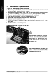
Replace the screw to your computer resulting from its power source and read the expansion card's installation manual before installing the expansion card in the motherboard. 4. Make sure the card is fully inserted into the expansion slot in the computer. 2. Ground yourself to prevent damage to secure the slot bracket .... 1. Install related driver in the slot and does not rock. Power on the slot and then lift the card straight out from the computer. GA-945GCM(X)-S2 Motherboard - 18 - Disconnect your computer's chassis cover, screws and slot bracket from the slot.
Replace the screw to your computer resulting from its power source and read the expansion card's installation manual before installing the expansion card in the motherboard. 4. Make sure the card is fully inserted into the expansion slot in the computer. 2. Ground yourself to prevent damage to secure the slot bracket .... 1. Install related driver in the slot and does not rock. Power on the slot and then lift the card straight out from the computer. GA-945GCM(X)-S2 Motherboard - 18 - Disconnect your computer's chassis cover, screws and slot bracket from the slot.

Manual
Page 20
... Connector) 3) CPU_FAN 4) SYS_FAN 5) FDD 6) IDE 7) SATAII0 / 1 / 2 / 3 8) PWR_LED 9) BATTERY 10) F_PANEL 11) F_AUDIO 12) CD_IN 13) SPDIF_IO 14) F_USB1 / F_USB2 15) COMB 16) CLR_CMOS 17) CI GA-945GCM(X)-S2 Motherboard - 20 - In addition to the default speakers settings, the ~ audio jacks can be reconfigured to the 2-/4-/6-/8-
... Connector) 3) CPU_FAN 4) SYS_FAN 5) FDD 6) IDE 7) SATAII0 / 1 / 2 / 3 8) PWR_LED 9) BATTERY 10) F_PANEL 11) F_AUDIO 12) CD_IN 13) SPDIF_IO 14) F_USB1 / F_USB2 15) COMB 16) CLR_CMOS 17) CI GA-945GCM(X)-S2 Motherboard - 20 - In addition to the default speakers settings, the ~ audio jacks can be reconfigured to the 2-/4-/6-/8-

Manual
Page 21
...(Only for 24-pin ATX) - 21 - Before connecting the power connector, please make sure that all the components on the motherboard. Align the power connector with its proper location on the motherboard before plugging in the power cord; Caution! It is recommended that a power supply that can withstand high power consumption be... unable to start . Please use a power supply that provides a 24-pin ATX power connector, please remove the small cover on the power connector on the motherboard and connect tightly. The ATX_12V power connector mainly supplies power to the CPU.
...(Only for 24-pin ATX) - 21 - Before connecting the power connector, please make sure that all the components on the motherboard. Align the power connector with its proper location on the motherboard before plugging in the power cord; Caution! It is recommended that a power supply that can withstand high power consumption be... unable to start . Please use a power supply that provides a 24-pin ATX power connector, please remove the small cover on the power connector on the motherboard and connect tightly. The ATX_12V power connector mainly supplies power to the CPU.

Manual
Page 22
.... The black connector wire is used to connect the FDD cable while the other end of the foolproof groove in the FDD connector. 34 33 2 1 GA-945GCM(X)-S2 Motherboard - 22 -
.... The black connector wire is used to connect the FDD cable while the other end of the foolproof groove in the FDD connector. 34 33 2 1 GA-945GCM(X)-S2 Motherboard - 22 -

Manual
Page 24
Definition 1 1 MPD+ 2 MPD- 3 MPD- 9) BATTERY GA-945GCM(X)-S2 Motherboard Danger of used batteries according to the manufacturer's instructions. Gently take out the battery and put it aside for about one minute. (Or you want ...
Definition 1 1 MPD+ 2 MPD- 3 MPD- 9) BATTERY GA-945GCM(X)-S2 Motherboard Danger of used batteries according to the manufacturer's instructions. Gently take out the battery and put it aside for about one minute. (Or you want ...

Manual
Page 26
.... English 11) F_AUDIO (Front Audio Connector) This connector supports either HD (High Definition) or AC'97 front panel audio module. Definition 1 CD-L 1 2 GND 3 GND 4 CD-R GA-945GCM(X)-S2 Motherboard - 26 - For optional front panel audio module, please contact your chassis manufacturer. 10 9 HD Audio: Pin No. 1 2 3 4 5 6 7 8 9 10 2 Definition MIC2_L GND MIC2_R -ACZ_DET LINE2_R FSENSE1...
.... English 11) F_AUDIO (Front Audio Connector) This connector supports either HD (High Definition) or AC'97 front panel audio module. Definition 1 CD-L 1 2 GND 3 GND 4 CD-R GA-945GCM(X)-S2 Motherboard - 26 - For optional front panel audio module, please contact your chassis manufacturer. 10 9 HD Audio: Pin No. 1 2 3 4 5 6 7 8 9 10 2 Definition MIC2_L GND MIC2_R -ACZ_DET LINE2_R FSENSE1...

Manual
Page 28
... NDSRBNRTSBNCTSBNRIBNo Pin 16) CLR_CMOS (Clear CMOS) You may clear the CMOS data to avoid improper use of the COMB connector. Open: Normal Short: Clear CMOS GA-945GCM(X)-S2 Motherboard - 28 - To clear CMOS, temporarily short the two pins. Check the pin assignments while you connect the COMB cable.
... NDSRBNRTSBNCTSBNRIBNo Pin 16) CLR_CMOS (Clear CMOS) You may clear the CMOS data to avoid improper use of the COMB connector. Open: Normal Short: Clear CMOS GA-945GCM(X)-S2 Motherboard - 28 - To clear CMOS, temporarily short the two pins. Check the pin assignments while you connect the COMB cable.

Manual
Page 30
English GA-945GCM(X)-S2 Motherboard - 30 -
English GA-945GCM(X)-S2 Motherboard - 30 -


