
User Manual
Page 6
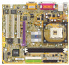
...5 GA-8SIMLH Motherboard Layout 7 Chapter 2 Hardware Installation Process 8 Step 1: Install the Central Processing Unit (CPU 9 Step1-1 : CPU Installation 9 Step1-2 : CPU Heat Sink Installation 10 Step 2: Install memory modules 11 Step 3: Install expansion cards 12 Step 4: Connect ribbon cables, cabinet wires, and power supply 13 Step 4-1 : I/O Back Panel Introduction 13 Step 4-2 : Connectors Introduction 15 Chapter 3 BIOS Setup 23 The Main Menu (For example: BIOS Ver. : F1o 24 Standard CMOS Features 26 Advanced BIOS Features 29 Integrated Peripherals 31 Power Management Setup 35...
...5 GA-8SIMLH Motherboard Layout 7 Chapter 2 Hardware Installation Process 8 Step 1: Install the Central Processing Unit (CPU 9 Step1-1 : CPU Installation 9 Step1-2 : CPU Heat Sink Installation 10 Step 2: Install memory modules 11 Step 3: Install expansion cards 12 Step 4: Connect ribbon cables, cabinet wires, and power supply 13 Step 4-1 : I/O Back Panel Introduction 13 Step 4-2 : Connectors Introduction 15 Chapter 3 BIOS Setup 23 The Main Menu (For example: BIOS Ver. : F1o 24 Standard CMOS Features 26 Advanced BIOS Features 29 Integrated Peripherals 31 Power Management Setup 35...
User Manual
Page 8
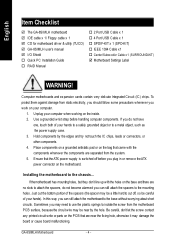
... the PCB that the ATX power supply is switched off , so be a little hard to the mounting holes. Just cut off before handling computer components. English Item Checklist þ The GA-8SIMLH motherboard þ IDE cable x 1/ Floppy cable x 1 þ CD for motherboard driver & utility (TUCD) þ GA-8SIMLH user's manual þ I/O Shield o Quick PC Installation Guide o RAID Manual o 2 Port USB Cable x 1 o 4 Port USB Cable x 1 o SPDIF-KIT x 1 (SPD-KIT) o IEEE 1394 Cable x1 o Center/Subw oofer Cable x 1 (SURROUND-KIT) þ Motherboard Settings Label WARNING! If...
... the PCB that the ATX power supply is switched off , so be a little hard to the mounting holes. Just cut off before handling computer components. English Item Checklist þ The GA-8SIMLH motherboard þ IDE cable x 1/ Floppy cable x 1 þ CD for motherboard driver & utility (TUCD) þ GA-8SIMLH user's manual þ I/O Shield o Quick PC Installation Guide o RAID Manual o 2 Port USB Cable x 1 o 4 Port USB Cable x 1 o SPDIF-KIT x 1 (SPD-KIT) o IEEE 1394 Cable x1 o Center/Subw oofer Cable x 1 (SURROUND-KIT) þ Motherboard Settings Label WARNING! If...
User Manual
Page 10
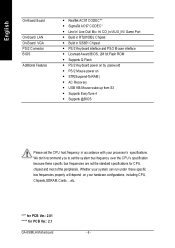
... Chipset - Supports Q-Flash - We don't recommend you to set the CPU host frequency in accordance with your hardware configurations, including CPU, Chipsets,SDRAM,Cards... .etc. PS/2 Keyboard power on - Licensed Award BIOS, 2M bit Flash ROM - Supports @BIOS Please set the system bus frequency over the CPU's specification because these specific bus frequencies properly will depend on your processor's specifications. Supports EasyTune 4 - "*" for PCB Ver.: 2.01 "**" for CPU, chipset and most of the peripherals. AC Recovery - English On-Board Sound On-Board LAN On-Board VGA...
... Chipset - Supports Q-Flash - We don't recommend you to set the CPU host frequency in accordance with your hardware configurations, including CPU, Chipsets,SDRAM,Cards... .etc. PS/2 Keyboard power on - Licensed Award BIOS, 2M bit Flash ROM - Supports @BIOS Please set the system bus frequency over the CPU's specification because these specific bus frequencies properly will depend on your processor's specifications. Supports EasyTune 4 - "*" for PCB Ver.: 2.01 "**" for CPU, chipset and most of the peripherals. AC Recovery - English On-Board Sound On-Board LAN On-Board VGA...
User Manual
Page 12
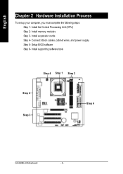
English Chapter 2 Hardware Installation Process To set up your computer, you must complete the following steps: Step 1- Setup BIOS software Step 6- Install supporting software tools Step 4 Step 1 Step 2 Step 4 Step 3 Step 4 GA-8SIMLH Motherboard - 8 - Connect ribbon cables, cabinet wires, and power supply Step 5- Install expansion cards Step 4- Install memory modules Step 3- Install the Central Processing Unit (CPU) Step 2-
English Chapter 2 Hardware Installation Process To set up your computer, you must complete the following steps: Step 1- Setup BIOS software Step 6- Install supporting software tools Step 4 Step 1 Step 2 Step 4 Step 3 Step 4 GA-8SIMLH Motherboard - 8 - Connect ribbon cables, cabinet wires, and power supply Step 5- Install expansion cards Step 4- Install memory modules Step 3- Install the Central Processing Unit (CPU) Step 2-
User Manual
Page 16
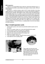
... the computer, if necessary, setup BIOS utility of the AGP slot when you try to its availability, pricing and overall market support. AGP Card GA-8SIMLH Motherboard Please carefully pull out the small whitedrawable bar at both the rising and falling edge of 2.1GB per second, DDR memory enables system OEMs to build high performance and low latency DRAM subsystems that allows easy...
... the computer, if necessary, setup BIOS utility of the AGP slot when you try to its availability, pricing and overall market support. AGP Card GA-8SIMLH Motherboard Please carefully pull out the small whitedrawable bar at both the rising and falling edge of 2.1GB per second, DDR memory enables system OEMs to build high performance and low latency DRAM subsystems that allows easy...
User Manual
Page 18
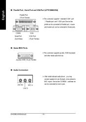
... Serial Port (9 pin Male) VGA VGA Port (15 pin Female) x Game /MIDI Ports Joystick/ MIDI (15 pin Female) ØThis connector supports joystick, MIDI keyboard and other relate audio devices. Device like CD-ROM , walkman etc can be connected to Parallel port ; GA-8SIMLH Motherboard - 14 - y Audio Connectors Line Out MIC In Line In Ø After install onboard audio driver, you may connect speaker to Line Out jack, micro phone to Serial ports. English w Parallel Port , Serial Port and VGA Port (LPT/COMA/VGA) Parallel Port (25 pin Female...
... Serial Port (9 pin Male) VGA VGA Port (15 pin Female) x Game /MIDI Ports Joystick/ MIDI (15 pin Female) ØThis connector supports joystick, MIDI keyboard and other relate audio devices. Device like CD-ROM , walkman etc can be connected to Parallel port ; GA-8SIMLH Motherboard - 14 - y Audio Connectors Line Out MIC In Line In Ø After install onboard audio driver, you may connect speaker to Line Out jack, micro phone to Serial ports. English w Parallel Port , Serial Port and VGA Port (LPT/COMA/VGA) Parallel Port (25 pin Female...
User Manual
Page 20
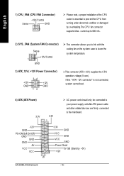
... CPU operation voltage (Vcore). If this " ATX+ 12V connector" is essential to prevent the CPU from running under abnormal condition or damaged by +5V) +12V GA-8SIMLH Motherboard - 16 - English 1) CPU_FAN (CPU FAN Connector) +12V/C ontrol Sense GND 1 Ø Please note, a proper installation of the CPU cooler is not connected, system cannot boot. 4) ATX (ATX Power) 3.3V 3.3V 1 Ø AC power cord should only be connected to your power supply unit after ATX power cable...
... CPU operation voltage (Vcore). If this " ATX+ 12V connector" is essential to prevent the CPU from running under abnormal condition or damaged by +5V) +12V GA-8SIMLH Motherboard - 16 - English 1) CPU_FAN (CPU FAN Connector) +12V/C ontrol Sense GND 1 Ø Please note, a proper installation of the CPU cooler is not connected, system cannot boot. 4) ATX (ATX Power) 3.3V 3.3V 1 Ø AC power cord should only be connected to your power supply unit after ATX power cable...

User Manual
Page 22
...) BAT1 (Battery) + GA-8SIMLH Motherboard CAUTI ON v Danger of used batteries according to the manufacturer's instructions. - 18 - v Dispose of explosion if battery is incorrectly replaced. English 9) F_PANEL (2x10 pins Connector) MPD+ MPDPW+ PWSPK+ SPK- 21 1 1 20 11 1 19 HD+ HDRSTRST+ NC HD (IDE Hard Disk Activ e LED) SPK (Speaker Connector) RST (Reset Switch) PW (Soft Power Connector) MPD(Message LED/Power/ Sleep LED) NC Pin 1: LED anode(+) Pin 2: LED cathode(-) Pin 1: VCC(+) Pin 2- v Replace only with the same or equivalent type recommended by...
...) BAT1 (Battery) + GA-8SIMLH Motherboard CAUTI ON v Danger of used batteries according to the manufacturer's instructions. - 18 - v Dispose of explosion if battery is incorrectly replaced. English 9) F_PANEL (2x10 pins Connector) MPD+ MPDPW+ PWSPK+ SPK- 21 1 1 20 11 1 19 HD+ HDRSTRST+ NC HD (IDE Hard Disk Activ e LED) SPK (Speaker Connector) RST (Reset Switch) PW (Soft Power Connector) MPD(Message LED/Power/ Sleep LED) NC Pin 1: LED anode(+) Pin 2: LED cathode(-) Pin 1: VCC(+) Pin 2- v Replace only with the same or equivalent type recommended by...

User Manual
Page 24
... the pin assignment while you connect the front USB cable. GND USB Dx+ 16) COMB (COM B Connector)(White) N DTRBNSINB N DSRB- Please contact your system to enable or disable the "Case Open"item inBIOS if the system case begin remove. GA-8SIMLH Motherboard - 20 - N SOU TB GND N RIBN RTSB- Ø Be careful with the polarity of the COMB connector. Please contact your nearest dealer for optional COMB cable...
... the pin assignment while you connect the front USB cable. GND USB Dx+ 16) COMB (COM B Connector)(White) N DTRBNSINB N DSRB- Please contact your system to enable or disable the "Case Open"item inBIOS if the system case begin remove. GA-8SIMLH Motherboard - 20 - N SOU TB GND N RIBN RTSB- Ø Be careful with the polarity of the COMB connector. Please contact your nearest dealer for optional COMB cable...
User Manual
Page 28
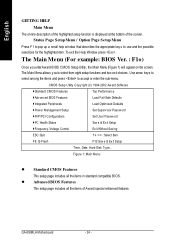
... This setup page includes all the items of the screen. The Main Menu allows you enterAward BIOS CMOS Setup Utility, the Main Menu (Figure 1) will appear on -line description of the highlighted setup function is displayed at the bottom of Award special enhanced features. Status Page Setup Menu / Option Page Setup Menu Press F1 to pop up a small help window that describes the appropriate keys to accept or enter the sub-menu. GA-8SIMLH Motherboard...
... This setup page includes all the items of the screen. The Main Menu allows you enterAward BIOS CMOS Setup Utility, the Main Menu (Figure 1) will appear on -line description of the highlighted setup function is displayed at the bottom of Award special enhanced features. Status Page Setup Menu / Option Page Setup Menu Press F1 to pop up a small help window that describes the appropriate keys to accept or enter the sub-menu. GA-8SIMLH Motherboard...

User Manual
Page 31
... HDD type. For example, 1 p.m. There are two types: auto type, and manual type. Number of cy linders 8HEADS Number of heads 8PRECOMP Write precomp 8LANDZONE Landing zone 8SECTORSNumber of hard disk from the keyboard and press . Auto type which will not work properly if you enter improper information for this category. BIOS Setup The time is user-definable; Note that has been installed in the computer. 8None No floppy...
... HDD type. For example, 1 p.m. There are two types: auto type, and manual type. Number of cy linders 8HEADS Number of heads 8PRECOMP Write precomp 8LANDZONE Landing zone 8SECTORSNumber of hard disk from the keyboard and press . Auto type which will not work properly if you enter improper information for this category. BIOS Setup The time is user-definable; Note that has been installed in the computer. 8None No floppy...

User Manual
Page 35
... stem Share Memory Size [32MB] USB Controller [Enabled] [ATA66/100/133] USB Legacy Support [Disabled] Set Conductor cable On Board LAN Function [Enabled] to ATA66/100/133(80-pins) Init Display First Onboard Serial Port A [AGP] [3F8/IRQ4] [ATA33] Onboard Serial Port B [2F8/IRQ3] Set Conductor cable Serial Port B Mode [Normal] to ATA33(40-pins) Onboard Parallel Port [378/IRQ7] Parallel Port Mode [ECP] x EPP Mode Select EPP1.7 ECP Mode Use DMA [3] Game Port Address [201] Midi Port Address [330] Midi Port IRQ [10] higf: Mov e Enter:Select +/-/PU...
... stem Share Memory Size [32MB] USB Controller [Enabled] [ATA66/100/133] USB Legacy Support [Disabled] Set Conductor cable On Board LAN Function [Enabled] to ATA66/100/133(80-pins) Init Display First Onboard Serial Port A [AGP] [3F8/IRQ4] [ATA33] Onboard Serial Port B [2F8/IRQ3] Set Conductor cable Serial Port B Mode [Normal] to ATA33(40-pins) Onboard Parallel Port [378/IRQ7] Parallel Port Mode [ECP] x EPP Mode Select EPP1.7 ECP Mode Use DMA [3] Game Port Address [201] Midi Port Address [330] Midi Port IRQ [10] higf: Mov e Enter:Select +/-/PU...

User Manual
Page 36
... Board LAN Function 8Disabled 8Enabled Disable this function. C On-Chip Primary PCI IDE 8Enabled Enable onboard 1st channel IDE port. (Default v alue) 8Disabled Disable onboard 1st channel IDE port. Enable Onboard Lan Chip function. (Default Value) GA-8SIMLH Motherboard - 32 - C System Share Memory Size 84MB/8MB/16MB/32MB/64MB Set onchip VGA shared memory size.(Default Value:32MB) C USB Controller 8Enabled Enable USB Controller. (Default v alue) 8Disabled Disable USB Controller. English C IDE2 Conductor Cable 8Auto Will be automatically detected by BIOS. (Default...
... Board LAN Function 8Disabled 8Enabled Disable this function. C On-Chip Primary PCI IDE 8Enabled Enable onboard 1st channel IDE port. (Default v alue) 8Disabled Disable onboard 1st channel IDE port. Enable Onboard Lan Chip function. (Default Value) GA-8SIMLH Motherboard - 32 - C System Share Memory Size 84MB/8MB/16MB/32MB/64MB Set onchip VGA shared memory size.(Default Value:32MB) C USB Controller 8Enabled Enable USB Controller. (Default v alue) 8Disabled Disable USB Controller. English C IDE2 Conductor Cable 8Auto Will be automatically detected by BIOS. (Default...

User Manual
Page 39
...:ss) 0 0 0 Pow er LED in "Off" state. (Default Value) - 35 - C Soft-off by Alarm Disabled Set suspend ty pe to x Month Alarm NA Suspend to RAM under PME Ev ent Wake Up Enabled ACPI OS Pow er On by Key board Disabled Pow er On by Mouse Disabled [S3] Resume by PWR_BTTN 8Off The user press the pow er button once, he can enter suspend mode.
...:ss) 0 0 0 Pow er LED in "Off" state. (Default Value) - 35 - C Soft-off by Alarm Disabled Set suspend ty pe to x Month Alarm NA Suspend to RAM under PME Ev ent Wake Up Enabled ACPI OS Pow er On by Key board Disabled Pow er On by Mouse Disabled [S3] Resume by PWR_BTTN 8Off The user press the pow er button once, he can enter suspend mode.

User Manual
Page 46
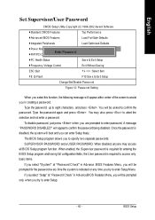
English Top Performance CMOS Setup Utility -Copy right (C) 1984-2002 Aw ard Softw are }Standard CMOS Features Top Performance }Adv anced Chipset Features Load Fail-Safe Defaults }Integrated PeripThoepralPserformance Load Optimized Defaults }Pow er Management Setup Set Superv isor Passw ord Disabled n] }PnP/PCI Configurations Set User Passw ord Enabled }PC Health Status Sav e & Ex it Setup }Frequency /Voltage Control Ex it Without Sav ing ESC:Quit F8: Q-Flash hi: Mov e ESC: Abort higf...
English Top Performance CMOS Setup Utility -Copy right (C) 1984-2002 Aw ard Softw are }Standard CMOS Features Top Performance }Adv anced Chipset Features Load Fail-Safe Defaults }Integrated PeripThoepralPserformance Load Optimized Defaults }Pow er Management Setup Set Superv isor Passw ord Disabled n] }PnP/PCI Configurations Set User Passw ord Enabled }PC Health Status Sav e & Ex it Setup }Frequency /Voltage Control Ex it Without Sav ing ESC:Quit F8: Q-Flash hi: Mov e ESC: Abort higf...
User Manual
Page 49
... Adv ance BIOS Features Menu, y ou will appear at "Password Check"in creating a password. You may access all BIOS Setup program function. BIOS Setup A message "PASSWORD DISABLED" will boot and you can enter Setup freely. Type the password again and press . Once the password is disabled, the system will appear to confirm the password being disabled. When disabled, anyone may also press to abort the selection and not enter a password. English Set Supervisor/User Password CMOS Setup Utility -Copy...
... Adv ance BIOS Features Menu, y ou will appear at "Password Check"in creating a password. You may access all BIOS Setup program function. BIOS Setup A message "PASSWORD DISABLED" will boot and you can enter Setup freely. Type the password again and press . Once the password is disabled, the system will appear to confirm the password being disabled. When disabled, anyone may also press to abort the selection and not enter a password. English Set Supervisor/User Password CMOS Setup Utility -Copy...

User Manual
Page 55
... and use manydifferenthardware or BIOS tools to do "Overclock" ateasy step . Users can "Save" this is a saferway for both normaland powerusers. "Advanced Mode", allows users to change the system bus / AGP / Memory working frequency in "Overclock", what's the truth? Therefore, this setting and "Load" itin nexttime. But have autoed and immediate CPU overclocking. But as to pave the way for any damage or instability to your processor, motherboard, or...
... and use manydifferenthardware or BIOS tools to do "Overclock" ateasy step . Users can "Save" this is a saferway for both normaland powerusers. "Advanced Mode", allows users to change the system bus / AGP / Memory working frequency in "Overclock", what's the truth? Therefore, this setting and "Load" itin nexttime. But have autoed and immediate CPU overclocking. But as to pave the way for any damage or instability to your processor, motherboard, or...

User Manual
Page 64
... System will be taken effectnextboot-up. AMIBIOS SETUP - Use the arrows to CM OS & Exit SETUP GA-8SIMLH Motherboard - 60 - All Rights Reserved 1st Boot Device 2nd Boot Device 3rd Boot Device S.M .A.R.T. All Rights Reserved STANDARD CMOS SETUP INTEGRATED PERIPHERALS BIOS FEATURES SETUP HARDWARE MONITOR & M ISC SETUP CHIPSET FEATURES SETUP SUPERVISOR PASSWORD POWER MANAGEMENT SETUP USER PASSWORD PNP / PCI CONFIGURATIONSave to CMOS and EXIDIET H(YD/DNA)?UTYO DETECTION LOAD BIOS DEFAULTS SAVE & EXIT SETUP LOAD SETUP DEFAULTS EXIT WITHOUT SAVING ESC: Quit hifg : Select...
... System will be taken effectnextboot-up. AMIBIOS SETUP - Use the arrows to CM OS & Exit SETUP GA-8SIMLH Motherboard - 60 - All Rights Reserved 1st Boot Device 2nd Boot Device 3rd Boot Device S.M .A.R.T. All Rights Reserved STANDARD CMOS SETUP INTEGRATED PERIPHERALS BIOS FEATURES SETUP HARDWARE MONITOR & M ISC SETUP CHIPSET FEATURES SETUP SUPERVISOR PASSWORD POWER MANAGEMENT SETUP USER PASSWORD PNP / PCI CONFIGURATIONSave to CMOS and EXIDIET H(YD/DNA)?UTYO DETECTION LOAD BIOS DEFAULTS SAVE & EXIT SETUP LOAD SETUP DEFAULTS EXIT WITHOUT SAVING ESC: Quit hifg : Select...
User Manual
Page 80
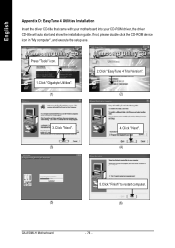
If not, please double click the CD-ROM device icon in "My computer", and execute the setup.exe. English RApepvenisdiixoDn: EHaissyTtuonrey4 Utilities Installation Insert the driver CD-title that came with your motherboard into your CD-ROM driver, the driver CD-title will auto start and show the installation guide. Press "Tools" icon. 1.Click "Gigabyte Utilities". (1) 2.Click "EasyTune 4 Trial Version". (2) 3.Click "Next". (3) 4.Click "Next". (4) (5) GA-8SIMLH Motherboard 5.Click "Finish" to restart computer. (6) - 76 -
If not, please double click the CD-ROM device icon in "My computer", and execute the setup.exe. English RApepvenisdiixoDn: EHaissyTtuonrey4 Utilities Installation Insert the driver CD-title that came with your motherboard into your CD-ROM driver, the driver CD-title will auto start and show the installation guide. Press "Tools" icon. 1.Click "Gigabyte Utilities". (1) 2.Click "EasyTune 4 Trial Version". (2) 3.Click "Next". (3) 4.Click "Next". (4) (5) GA-8SIMLH Motherboard 5.Click "Finish" to restart computer. (6) - 76 -

User Manual
Page 81
... Desktop Management Interface DIMM Dual Inline Memory Module DRM Dual Retention Mechanism DRAM Dynamic Random Access Memory DDR Double Data Rate ECP Extended Capabilities Port ESCD Extended System Configuration Data ECC Error Checking and Correcting EMC Electromagnetic Compatibility EPP Enhanced Parallel Port ESD Electrostatic Discharge FDD Floppy Disk Device FSB Front Side Bus HDD Hard Disk Device IDE Integrated Dual Channel Enhanced IRQ Interrupt Request I/O Input / Output IOAPIC Input Output Advanced Programmable Input Controller...
... Desktop Management Interface DIMM Dual Inline Memory Module DRM Dual Retention Mechanism DRAM Dynamic Random Access Memory DDR Double Data Rate ECP Extended Capabilities Port ESCD Extended System Configuration Data ECC Error Checking and Correcting EMC Electromagnetic Compatibility EPP Enhanced Parallel Port ESD Electrostatic Discharge FDD Floppy Disk Device FSB Front Side Bus HDD Hard Disk Device IDE Integrated Dual Channel Enhanced IRQ Interrupt Request I/O Input / Output IOAPIC Input Output Advanced Programmable Input Controller...


