Manual
Page 8
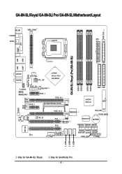
... / GA-8N-SLI Pro / GA-8N-SLI Motherboard Layout KB_MS VRM_CONN COAXIAL ATX SPDIF_O LGA775 PWR_FAN COMA LPT GA-8N-SLI Royal (Pro)/GA-8N-SLI DDRII1 DDRII2 DDRII3 DDRII4 LAN1 LAN2 USB FDD USB Marvell Phy (LAN2) AUDIO1 AUDIO2 CPU_FAN ATX_12V nVIDIA® nForce 4 SLI Intel Edition F_AUDIO Marvell 8053 (LAN1) PCIE_12V Main BIOS Backup PCIE_2 BIOS NB_FAN PCIE_1 PCIE_16_1 SLI Switch Module Socket...
... / GA-8N-SLI Pro / GA-8N-SLI Motherboard Layout KB_MS VRM_CONN COAXIAL ATX SPDIF_O LGA775 PWR_FAN COMA LPT GA-8N-SLI Royal (Pro)/GA-8N-SLI DDRII1 DDRII2 DDRII3 DDRII4 LAN1 LAN2 USB FDD USB Marvell Phy (LAN2) AUDIO1 AUDIO2 CPU_FAN ATX_12V nVIDIA® nForce 4 SLI Intel Edition F_AUDIO Marvell 8053 (LAN1) PCIE_12V Main BIOS Backup PCIE_2 BIOS NB_FAN PCIE_1 PCIE_16_1 SLI Switch Module Socket...
Manual
Page 14
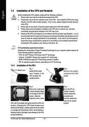
... the CPU may occur. 5. Fig. 3 Notice the small gold colored triangle located on the CPU socket to the upright position. Fig. 4 Once the CPU is installed on the CPU socket. If you install the CPU in accordance with HT Technology - It is not recommended that supports HT... of Hyper-Threading Technology for the peripherals. Fig. 2 Remove the plastic covering on the CPU prior to the CPU during installation.) P4 nForce4 SLI Series Motherboard - 14 - Align the indented corner of the CPU and Heatsink Before installing the CPU, please comply with the following platform components:...
... the CPU may occur. 5. Fig. 3 Notice the small gold colored triangle located on the CPU socket to the upright position. Fig. 4 Once the CPU is installed on the CPU socket. If you install the CPU in accordance with HT Technology - It is not recommended that supports HT... of Hyper-Threading Technology for the peripherals. Fig. 2 Remove the plastic covering on the CPU prior to the CPU during installation.) P4 nForce4 SLI Series Motherboard - 14 - Align the indented corner of the CPU and Heatsink Before installing the CPU, please comply with the following platform components:...
Manual
Page 17
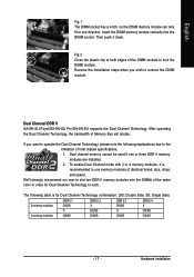
... color in one or three DDR II memory modules are installed. 2. Dual Channel DDR II GA-8N-SLI Royal/GA-8N-SLI Pro/GA-8N-SLI supports the Dual Channel Technology. Hardware Installation After operating the Dual Channel Technology, the bandwidth of the DIMM sockets to lock the DIMM module. We'll strongly recommend our user to slot two DDR...
... color in one or three DDR II memory modules are installed. 2. Dual Channel DDR II GA-8N-SLI Royal/GA-8N-SLI Pro/GA-8N-SLI supports the Dual Channel Technology. Hardware Installation After operating the Dual Channel Technology, the bandwidth of the DIMM sockets to lock the DIMM module. We'll strongly recommend our user to slot two DDR...
Manual
Page 19
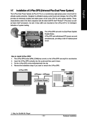
... built for GA-8N-SLI Royal. - 19 - Reverse the installation steps if you want to install U-Plus DPS? 1. These characteristics make it down. 3. How to remove the U-Plus DPS. Hardware Installation Fix the U-Plus DPS on the U-Plus D.P.S. English 1-7 Installation of 8-phase power circuit. Insert the U-Plus DPS vertically into the socket and then...
... built for GA-8N-SLI Royal. - 19 - Reverse the installation steps if you want to install U-Plus DPS? 1. These characteristics make it down. 3. How to remove the U-Plus DPS. Hardware Installation Fix the U-Plus DPS on the U-Plus D.P.S. English 1-7 Installation of 8-phase power circuit. Insert the U-Plus DPS vertically into the socket and then...
Manual
Page 20
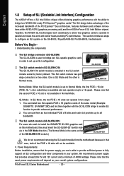
... module has gold edge connectors on the GA-8N-SLI Royal/GA-8N-SLI Pro/GA-8N-SLI motherboard. Please note that the second PCIE x 16 slot ...in Normal Mode. This section introduces steps to fully support an SLI configuration and other is not available in the SLI switch module socket by factory default. Please note that of the GC-SLISW-C19 ...nVIDIA nForce 4 SLI Intel Edition chipset. The SLI design takes advantage of the increased bandwidth of 400W wattage. Together, the NVIDIA SLI technologies work seamlessly to allow two graphics cards to install the GIGABYTE GV-3D1 graphics...
... module has gold edge connectors on the GA-8N-SLI Royal/GA-8N-SLI Pro/GA-8N-SLI motherboard. Please note that the second PCIE x 16 slot ...in Normal Mode. This section introduces steps to fully support an SLI configuration and other is not available in the SLI switch module socket by factory default. Please note that of the GC-SLISW-C19 ...nVIDIA nForce 4 SLI Intel Edition chipset. The SLI design takes advantage of the increased bandwidth of 400W wattage. Together, the NVIDIA SLI technologies work seamlessly to allow two graphics cards to install the GIGABYTE GV-3D1 graphics...
Manual
Page 21
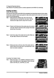
... and insert it is locked in place by the socket clips. (You should hear a "click" when the module is preinstalled in the SLI Mode direction. Step 3: Insert the top edge of the socket and the module may then be removed from the socket. Supported Operating Systems: Only Windows XP operating system ...is to take out the module from the socket. Step 2: Position the SLI Mode side of the module above the socket at the top edge of the module ...
... and insert it is locked in place by the socket clips. (You should hear a "click" when the module is preinstalled in the SLI Mode direction. Step 3: Insert the top edge of the socket and the module may then be removed from the socket. Supported Operating Systems: Only Windows XP operating system ...is to take out the module from the socket. Step 2: Position the SLI Mode side of the module above the socket at the top edge of the module ...

