
Manual
Page 1
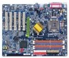
The factory default for this card in it . Note : Although Gigabyte's AG32S(G) graphics card is based on ATi Rage 128 Pro chip, the design of AG32S(G) is compliance with 2X(3.3V)/4X(1.5V) mode AGP slot, ... graphics card manufacturer & some SiS 305 cards, their golden finger is 2X(3.3V). The GA-8IPE775 Series (or any AGP 4X/8X only) motherboards might not function properly, If you install PCI cards, please remove the Dual BIOS label from PCI slots if there is fully understood and practiced. Before you install this...
The factory default for this card in it . Note : Although Gigabyte's AG32S(G) graphics card is based on ATi Rage 128 Pro chip, the design of AG32S(G) is compliance with 2X(3.3V)/4X(1.5V) mode AGP slot, ... graphics card manufacturer & some SiS 305 cards, their golden finger is 2X(3.3V). The GA-8IPE775 Series (or any AGP 4X/8X only) motherboards might not function properly, If you install PCI cards, please remove the Dual BIOS label from PCI slots if there is fully understood and practiced. Before you install this...
Manual
Page 6
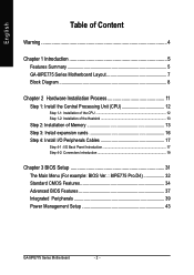
English Table of Content Warning 4 Chapter 1 Introduction 5 Features Summary 5 GA-8IPE775 Series Motherboard Layout 7 Block Diagram 8 Chapter 2 Hardware Installation Process 11 Step 1: Install the Central Processing Unit (CPU 12 Step ... 16 Step 4: Install I/O Peripherals Cables 17 Step 4-1: I/O Back Panel Introduction 17 Step 4-2: Connectors Introduction 19 Chapter 3 BIOS Setup 31 The Main Menu (For example: BIOS Ver. : 8IPE775 Pro.D4 32 Standard CMOS Features 34 Advanced BIOS Features 37 Integrated Peripherals 39 Power Management Setup 43 GA-8IPE775 Series Motherboard - 2 -
English Table of Content Warning 4 Chapter 1 Introduction 5 Features Summary 5 GA-8IPE775 Series Motherboard Layout 7 Block Diagram 8 Chapter 2 Hardware Installation Process 11 Step 1: Install the Central Processing Unit (CPU 12 Step ... 16 Step 4: Install I/O Peripherals Cables 17 Step 4-1: I/O Back Panel Introduction 17 Step 4-2: Connectors Introduction 19 Chapter 3 BIOS Setup 31 The Main Menu (For example: BIOS Ver. : 8IPE775 Pro.D4 32 Standard CMOS Features 34 Advanced BIOS Features 37 Integrated Peripherals 39 Power Management Setup 43 GA-8IPE775 Series Motherboard - 2 -
Manual
Page 7
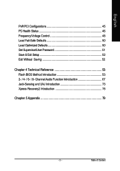
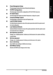
English PnP/PCI Configurations 45 PC Health Status 46 Frequency/Voltage Control 48 Load Fail-Safe Defaults 50 Load Optimized Defaults 50 Set Supervisor/User Password 51 Save & Exit Setup 52 Exit Without Saving 52 Chapter 4 Technical Reference 53 Flash BIOS Method Introduction 53 2- / 4- / 6- / 8- Table of Content Channel Audio Function Introduction 67 Jack-Sensing and UAJ Introduction 73 Xpress Recovery2 Introduction 75 Chapter 5 Appendix 79 - 3 -
English PnP/PCI Configurations 45 PC Health Status 46 Frequency/Voltage Control 48 Load Fail-Safe Defaults 50 Load Optimized Defaults 50 Set Supervisor/User Password 51 Save & Exit Setup 52 Exit Without Saving 52 Chapter 4 Technical Reference 53 Flash BIOS Method Introduction 53 2- / 4- / 6- / 8- Table of Content Channel Audio Function Introduction 67 Jack-Sensing and UAJ Introduction 73 Xpress Recovery2 Introduction 75 Chapter 5 Appendix 79 - 3 -
Manual
Page 10
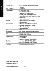
Only for GA-8IPE775 Pro. GA-8IPE775 Series Motherboard - 6 - English On-Board LAN On-Board IEEE1394 On-Board Sound Serial ATA Hardware Monitor I/O Control PS/2 Connector BIOS Additional Features Overclocking Form Factor y Build in Marvell 8001 Chipset (10/100/1000 Mbit) y 1 RJ45 port y Ti... and PS/2 Mouse interface y Licensed AWARD BIOS y Supports Dual BIOS /Q-Flash y Supports EasyTune y Supports @BIOS y Supports CPU Smart Fan Control function y Over Voltage (DDR/AGP/CPU) by BIOS y Over Clock (DDR/AGP/CPU/PCI) by BIOS y ATX size form factor; 30.5cm x 24.4cm Only for GA-8IPE775-G.
Only for GA-8IPE775 Pro. GA-8IPE775 Series Motherboard - 6 - English On-Board LAN On-Board IEEE1394 On-Board Sound Serial ATA Hardware Monitor I/O Control PS/2 Connector BIOS Additional Features Overclocking Form Factor y Build in Marvell 8001 Chipset (10/100/1000 Mbit) y 1 RJ45 port y Ti... and PS/2 Mouse interface y Licensed AWARD BIOS y Supports Dual BIOS /Q-Flash y Supports EasyTune y Supports @BIOS y Supports CPU Smart Fan Control function y Over Voltage (DDR/AGP/CPU) by BIOS y Over Clock (DDR/AGP/CPU/PCI) by BIOS y ATX size form factor; 30.5cm x 24.4cm Only for GA-8IPE775-G.
Manual
Page 12
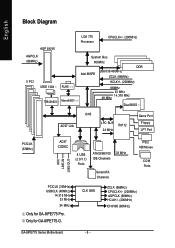
...+/- (200MHz) ICH3V66 (66MHz) GA-8IPE775 Series Motherboard - 8 - English Block Diagram AGP 8X/4X AGPCLK (66MHz) 5 PCI IEEE 1394 RJ45 TSB43AB23 Marvell 8001 LGA 775 Processor CPUCLK+/- (200MHz) System Bus 800MHz DDR 266/333/400MHz Intel 865PE ZCLK (66MHz) HCLK+/- (200MHz) 66MHz 33 MHz 48 MHz 14.318 MHz Dual BIOS AC97 Link ICH5... 33 MHz IDE Channels Serial ATA Channels PS/2 KB/Mouse COM Ports PCICLK (33MHz) USBCLK (48MHz) 14.318 MHz 33 MHz 24 MHz Only for GA-8IPE775-G.
...+/- (200MHz) ICH3V66 (66MHz) GA-8IPE775 Series Motherboard - 8 - English Block Diagram AGP 8X/4X AGPCLK (66MHz) 5 PCI IEEE 1394 RJ45 TSB43AB23 Marvell 8001 LGA 775 Processor CPUCLK+/- (200MHz) System Bus 800MHz DDR 266/333/400MHz Intel 865PE ZCLK (66MHz) HCLK+/- (200MHz) 66MHz 33 MHz 48 MHz 14.318 MHz Dual BIOS AC97 Link ICH5... 33 MHz IDE Channels Serial ATA Channels PS/2 KB/Mouse COM Ports PCICLK (33MHz) USBCLK (48MHz) 14.318 MHz 33 MHz 24 MHz Only for GA-8IPE775-G.
Manual
Page 15
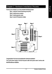
Install the Central Processing Unit (CPU) Step 2- Turn on the power supply or connect the power cable to the power outlet. English Chapter 2 Hardware Installation Process To set up your computer, you must complete the following steps: Step 1- Install I/O Peripherals Cables Step 4 Step 1 Step 2 Step 4 Step 4 Step 3 Congratulations! Continue with the BIOS/software installation. - 11 - You have accomplished the hardware installation! Install memory modules Step 3- Install expansion cards Step 4- Hardware Installation Process
Install the Central Processing Unit (CPU) Step 2- Turn on the power supply or connect the power cable to the power outlet. English Chapter 2 Hardware Installation Process To set up your computer, you must complete the following steps: Step 1- Install I/O Peripherals Cables Step 4 Step 1 Step 2 Step 4 Step 4 Step 3 Congratulations! Continue with the BIOS/software installation. - 11 - You have accomplished the hardware installation! Install memory modules Step 3- Install expansion cards Step 4- Hardware Installation Process
Manual
Page 16
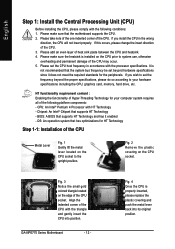
... does not meet the required standards for HT Technology Step 1-1: Installation of the CPU. 3. BIOS: A BIOS that supports HT Technology - English Step 1: Install the Central Processing Unit (CPU) Before installing the CPU, please comply with the following platform components: - GA-8IPE775 Series Motherboard - 12 - If you install the CPU in accordance with HT Technology -
... does not meet the required standards for HT Technology Step 1-1: Installation of the CPU. 3. BIOS: A BIOS that supports HT Technology - English Step 1: Install the Central Processing Unit (CPU) Before installing the CPU, please comply with the following platform components: - GA-8IPE775 Series Motherboard - 12 - If you install the CPU in accordance with HT Technology -
Manual
Page 18
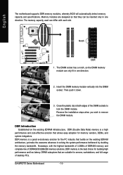
...fit in solving the system performance bottleneck by doubling the memory bandwidth. Insert the DIMM memory module vertically into the DIMM socket. GA-8IPE775 Series Motherboard - 14 - Memory modules are suitable for memory vendors, OEMs, and system integrators. DDR memory is the best ...that allows easy adoption for servers, workstations, and full range of desktop PCs. English The motherboard supports DDR memory modules, whereby BIOS will automatically detect memory capacity and specifications. Close the plastic clip at both edges of DDR400/333/266/200 memory solutions, ...
...fit in solving the system performance bottleneck by doubling the memory bandwidth. Insert the DIMM memory module vertically into the DIMM socket. GA-8IPE775 Series Motherboard - 14 - Memory modules are suitable for memory vendors, OEMs, and system integrators. DDR memory is the best ...that allows easy adoption for servers, workstations, and full range of desktop PCs. English The motherboard supports DDR memory modules, whereby BIOS will automatically detect memory capacity and specifications. Close the plastic clip at both edges of DDR400/333/266/200 memory solutions, ...
Manual
Page 20
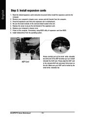
...from the operating system. drawable bar at the end of the AGP slot when you try to secure the slot bracket of expansion card from BIOS. 8. GA-8IPE775 Series Motherboard - 16 - Be sure the metal contacts on the slot .Make sure your computer's chassis cover. 7. Install related driver from... pull out the small white- Replace your AGP card is locked by the small white- Power on the computer, if necessary, setup BIOS utility of the expansion card. 6. Read the related expansion card's instruction document before install the expansion card into expansion slot in the slot...
...from the operating system. drawable bar at the end of the AGP slot when you try to secure the slot bracket of expansion card from BIOS. 8. GA-8IPE775 Series Motherboard - 16 - Be sure the metal contacts on the slot .Make sure your computer's chassis cover. 7. Install related driver from... pull out the small white- Replace your AGP card is locked by the small white- Power on the computer, if necessary, setup BIOS utility of the expansion card. 6. Read the related expansion card's instruction document before install the expansion card into expansion slot in the slot...
Manual
Page 33
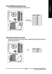
Definition 1 GND 2 TXP 3 TXN 7 1 4 GND 5 RXN 6 RXP 7 GND 21) CI (Chassis Intrusion, Case Open) This 2-pin connector allows your system to this connector. Hardware Installation Process English 20) SATA0/SATA1 (Serial ATA Connector) You can connect the Serial ATA device to enable or disable the "Case Open" item in BIOS, if the system case begin remove. Definition 1 1 Signal 2 GND - 29 - Pin No. Pin No.
Definition 1 GND 2 TXP 3 TXN 7 1 4 GND 5 RXN 6 RXP 7 GND 21) CI (Chassis Intrusion, Case Open) This 2-pin connector allows your system to this connector. Hardware Installation Process English 20) SATA0/SATA1 (Serial ATA Connector) You can connect the Serial ATA device to enable or disable the "Case Open" item in BIOS, if the system case begin remove. Definition 1 1 Signal 2 GND - 29 - Pin No. Pin No.
Manual
Page 35
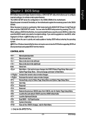
... to a new BIOS, either Gigabyte's Q-Flash or @BIOS utility can enter the BIOS setup screen by pressing "Ctrl + F1". BIOS Setup The CMOS SETUP saves the configuration in the right hand Select item Main Menu - When the power is turned off, the battery on , pushing the button during the BIOS POST (Power-On...previous CMOS value from CMOS, only for Option Page Setup Menu Load the file-safe default CMOS value from the Internet. When setting up BIOS for GA-8IPE775 Pro. - 31 - CONTROL KEYS Enter Move to previous item Move to next item Move to the item in the left hand Move to...
... to a new BIOS, either Gigabyte's Q-Flash or @BIOS utility can enter the BIOS setup screen by pressing "Ctrl + F1". BIOS Setup The CMOS SETUP saves the configuration in the right hand Select item Main Menu - When the power is turned off, the battery on , pushing the button during the BIOS POST (Power-On...previous CMOS value from CMOS, only for Option Page Setup Menu Load the file-safe default CMOS value from the Internet. When setting up BIOS for GA-8IPE775 Pro. - 31 - CONTROL KEYS Enter Move to previous item Move to next item Move to the item in the left hand Move to...
Manual
Page 36
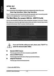
... setting you to use and the possible selections for GA-8IPE775 Pro. z Integrated Peripherals This setup page includes all the items in standard compatible BIOS. The Main Menu (For example: BIOS Ver. : 8IPE775 Pro.D4) Once you enter Award BIOS CMOS Setup Utility, the Main Menu will appear on...on the screen. The Main Menu allows you want, please press "Ctrl+F1" to accept or enter the sub-menu. GA-8IPE775 Series Motherboard - 32 - z Advanced BIOS Features This setup page includes all the items of the screen. CMOS Setup Utility-Copyright (C) 1984-2004 Award Software ` Standard...
... setting you to use and the possible selections for GA-8IPE775 Pro. z Integrated Peripherals This setup page includes all the items in standard compatible BIOS. The Main Menu (For example: BIOS Ver. : 8IPE775 Pro.D4) Once you enter Award BIOS CMOS Setup Utility, the Main Menu will appear on...on the screen. The Main Menu allows you want, please press "Ctrl+F1" to accept or enter the sub-menu. GA-8IPE775 Series Motherboard - 32 - z Advanced BIOS Features This setup page includes all the items of the screen. CMOS Setup Utility-Copyright (C) 1984-2004 Award Software ` Standard...
Manual
Page 37
..., or just to the system. z Set Supervisor password Change, set , or disable password. z Save & Exit Setup Save CMOS value settings to CMOS and exit setup. BIOS Setup
..., or just to the system. z Set Supervisor password Change, set , or disable password. z Save & Exit Setup Save CMOS value settings to CMOS and exit setup. BIOS Setup
Manual
Page 38
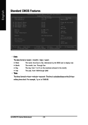
... On Base Memory Extended Memory Total Memory [All, But Keyboard] 640K 127M 128M 1 to 31 (or maximum allowed in . GA-8IPE775 Series Motherboard - 34 - The time is , , , . to Sat, determined by the BIOS and is 13:00:00. Week Month Day Year Time The week, from 1999 through 2098 The times format in...
... On Base Memory Extended Memory Total Memory [All, But Keyboard] 640K 127M 128M 1 to 31 (or maximum allowed in . GA-8IPE775 Series Motherboard - 34 - The time is , , , . to Sat, determined by the BIOS and is 13:00:00. Week Month Day Year Time The week, from 1999 through 2098 The times format in...
Manual
Page 39
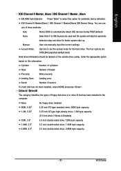
.... IDE Channel 0 Master(Slave) / IDE Channel 1 Master(Slave) IDE Device Setup. User can use one of three methods: Auto None Allows BIOS to set the access mode for automatic device detection. None No floppy drive installed 360K, 5.25" 1.2M, 5.25" 5.25 inch PC-type ... drive; 720K byte capacity 1.44M, 3.5" 2.88M, 3.5" 3.5 inch double-sided drive; 1.44M byte capacity. 3.5 inch double-sided drive; 2.88M byte capacity. - 35 - BIOS Setup You can manually input the correct settings Access Mode Use this to automatically detect IDE devices during POST(default) Select this if no IDE...
.... IDE Channel 0 Master(Slave) / IDE Channel 1 Master(Slave) IDE Device Setup. User can use one of three methods: Auto None Allows BIOS to set the access mode for automatic device detection. None No floppy drive installed 360K, 5.25" 1.2M, 5.25" 5.25 inch PC-type ... drive; 720K byte capacity 1.44M, 3.5" 2.88M, 3.5" 3.5 inch double-sided drive; 1.44M byte capacity. 3.5 inch double-sided drive; 2.88M byte capacity. - 35 - BIOS Setup You can manually input the correct settings Access Mode Use this to automatically detect IDE devices during POST(default) Select this if no IDE...

Manual
Page 40
...Test) of memory located above 1MB in the system. The category is display-only which is detected during the POST. Extended Memory The BIOS determines how much extended memory is 3 mode Floppy Drive. The category determines whether the computer will determine the amount of base (or ... map. All Errors Whenever the BIOS detects a non-fatal error the system boot will be stopped. Base Memory The POST of the base memory is typically 512 K for systems with 640 K or more memory installed on the motherboard. This is 3 mode Floppy Drive. GA-8IPE775 Series Motherboard - 36 - All...
...Test) of memory located above 1MB in the system. The category is display-only which is detected during the POST. Extended Memory The BIOS determines how much extended memory is 3 mode Floppy Drive. The category determines whether the computer will determine the amount of base (or ... map. All Errors Whenever the BIOS detects a non-fatal error the system boot will be stopped. Base Memory The POST of the base memory is typically 512 K for systems with 640 K or more memory installed on the motherboard. This is 3 mode Floppy Drive. GA-8IPE775 Series Motherboard - 36 - All...
Manual
Page 41
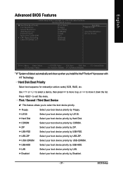
... Disabled. - 37 - Select your boot device priority by Hard Disk. Select your boot device priority by USB-HDD. BIOS Setup English Advanced BIOS Features CMOS Setup Utility-Copyright (C) 1984-2004 Award Software Advanced BIOS Features X Hard Disk Boot Priority First Boot Device Second Boot Device Third Boot Device Password Check Boot to select...
... Disabled. - 37 - Select your boot device priority by Hard Disk. Select your boot device priority by USB-HDD. BIOS Setup English Advanced BIOS Features CMOS Setup Utility-Copyright (C) 1984-2004 Award Software Advanced BIOS Features X Hard Disk Boot Priority First Boot Device Second Boot Device Third Boot Device Password Check Boot to select...

Manual
Page 43
...: Move Enter: Select F5: Previous Values +/-/PU/PD: Value F10: Save ESC: Exit F6: Fail-Save Default F7: Optimized Defaults F1: General Help Only for GA-8IPE775-G. - 39 - BIOS Setup Only for GA-8IPE775 Pro.
...: Move Enter: Select F5: Previous Values +/-/PU/PD: Value F10: Save ESC: Exit F6: Fail-Save Default F7: Optimized Defaults F1: General Help Only for GA-8IPE775-G. - 39 - BIOS Setup Only for GA-8IPE775 Pro.
Manual
Page 45
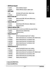
... address is 2F8. (Default value) Enable onboard Serial port 2 and address is 3E8. 2E8/IRQ3 Disabled Enable onboard Serial port 2 and address is 2E8. BIOS Setup Enable onboard Serial port 1 and address is 2E8. Only for GA-8IPE775-G. - 41 - Disabled Disable this function. (Default Value) Enabled Enable this function. Onboard Serial Port 1 Auto...
... address is 2F8. (Default value) Enable onboard Serial port 2 and address is 3E8. 2E8/IRQ3 Disabled Enable onboard Serial port 2 and address is 2E8. BIOS Setup Enable onboard Serial port 1 and address is 2E8. Only for GA-8IPE775-G. - 41 - Disabled Disable this function. (Default Value) Enabled Enable this function. Onboard Serial Port 1 Auto...
Manual
Page 47
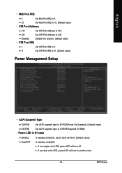
... x Time (hh:mm:ss) Alarm Power On By Mouse Power On By Keyboard x KB Power ON Password AC Back Function [S1(POS)] [Blinking] [Instant-off . BIOS Setup b. Disabled Disable this function. (Default value) CIR Port IRQ 5 Set CIR Port IRQ to 5. 11 Set CIR Port IRQ to 320.
... x Time (hh:mm:ss) Alarm Power On By Mouse Power On By Keyboard x KB Power ON Password AC Back Function [S1(POS)] [Blinking] [Instant-off . BIOS Setup b. Disabled Disable this function. (Default value) CIR Port IRQ 5 Set CIR Port IRQ to 5. 11 Set CIR Port IRQ to 320.


