
Manual
Page 1
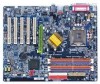
The GA-8IPE775 Series (or any AGP 4X/8X only) motherboards might experience system unable to 4X...BIOS label from PCI slots if there is AGP 4X/8X (1.5V). It can be switched between AGP 2X(3.3V) or 4X(1.5V) mode by Intel® 845(GE/PE) / 845(E/ G) / 850(E) / E7205 / 865(G/PE/P) / 875P. The factory default for this card without switching the jumper to boot up normally. The GA-8IPE775...8X notch Caution: AGP 2X card is compliance with 2X/4X mode AGP slot. Note : Although Gigabyte's AG32S(G) graphics card is based on ATi Rage 128 Pro chip, the design of AG32S(G) is not supported by...
The GA-8IPE775 Series (or any AGP 4X/8X only) motherboards might experience system unable to 4X...BIOS label from PCI slots if there is AGP 4X/8X (1.5V). It can be switched between AGP 2X(3.3V) or 4X(1.5V) mode by Intel® 845(GE/PE) / 845(E/ G) / 850(E) / E7205 / 865(G/PE/P) / 875P. The factory default for this card without switching the jumper to boot up normally. The GA-8IPE775...8X notch Caution: AGP 2X card is compliance with 2X/4X mode AGP slot. Note : Although Gigabyte's AG32S(G) graphics card is based on ATi Rage 128 Pro chip, the design of AG32S(G) is not supported by...
Manual
Page 6
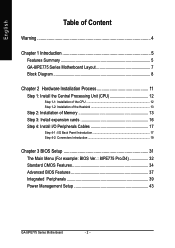
English Table of Content Warning 4 Chapter 1 Introduction 5 Features Summary 5 GA-8IPE775 Series Motherboard Layout 7 Block Diagram 8 Chapter 2 Hardware Installation Process 11 Step 1: Install the Central Processing Unit (CPU 12 Step ... 16 Step 4: Install I/O Peripherals Cables 17 Step 4-1: I/O Back Panel Introduction 17 Step 4-2: Connectors Introduction 19 Chapter 3 BIOS Setup 31 The Main Menu (For example: BIOS Ver. : 8IPE775 Pro.D4 32 Standard CMOS Features 34 Advanced BIOS Features 37 Integrated Peripherals 39 Power Management Setup 43 GA-8IPE775 Series Motherboard - 2 -
English Table of Content Warning 4 Chapter 1 Introduction 5 Features Summary 5 GA-8IPE775 Series Motherboard Layout 7 Block Diagram 8 Chapter 2 Hardware Installation Process 11 Step 1: Install the Central Processing Unit (CPU 12 Step ... 16 Step 4: Install I/O Peripherals Cables 17 Step 4-1: I/O Back Panel Introduction 17 Step 4-2: Connectors Introduction 19 Chapter 3 BIOS Setup 31 The Main Menu (For example: BIOS Ver. : 8IPE775 Pro.D4 32 Standard CMOS Features 34 Advanced BIOS Features 37 Integrated Peripherals 39 Power Management Setup 43 GA-8IPE775 Series Motherboard - 2 -
Manual
Page 7
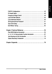
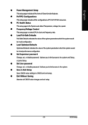
English PnP/PCI Configurations 45 PC Health Status 46 Frequency/Voltage Control 48 Load Fail-Safe Defaults 50 Load Optimized Defaults 50 Set Supervisor/User Password 51 Save & Exit Setup 52 Exit Without Saving 52 Chapter 4 Technical Reference 53 Flash BIOS Method Introduction 53 2- / 4- / 6- / 8- Table of Content Channel Audio Function Introduction 67 Jack-Sensing and UAJ Introduction 73 Xpress Recovery2 Introduction 75 Chapter 5 Appendix 79 - 3 -
English PnP/PCI Configurations 45 PC Health Status 46 Frequency/Voltage Control 48 Load Fail-Safe Defaults 50 Load Optimized Defaults 50 Set Supervisor/User Password 51 Save & Exit Setup 52 Exit Without Saving 52 Chapter 4 Technical Reference 53 Flash BIOS Method Introduction 53 2- / 4- / 6- / 8- Table of Content Channel Audio Function Introduction 67 Jack-Sensing and UAJ Introduction 73 Xpress Recovery2 Introduction 75 Chapter 5 Appendix 79 - 3 -
Manual
Page 10
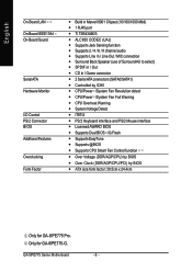
English On-Board LAN On-Board IEEE1394 On-Board Sound Serial ATA Hardware Monitor I/O Control PS/2 Connector BIOS Additional Features Overclocking Form Factor y Build in Marvell 8001 Chipset (10/100/1000 Mbit) y 1 RJ45 port y Ti TSB43AB23 y ...Mouse interface y Licensed AWARD BIOS y Supports Dual BIOS /Q-Flash y Supports EasyTune y Supports @BIOS y Supports CPU Smart Fan Control function y Over Voltage (DDR/AGP/CPU) by BIOS y Over Clock (DDR/AGP/CPU/PCI) by BIOS y ATX size form factor; 30.5cm x 24.4cm Only for GA-8IPE775-G. GA-8IPE775 Series Motherboard - 6 - Only for GA-8IPE775 Pro.
English On-Board LAN On-Board IEEE1394 On-Board Sound Serial ATA Hardware Monitor I/O Control PS/2 Connector BIOS Additional Features Overclocking Form Factor y Build in Marvell 8001 Chipset (10/100/1000 Mbit) y 1 RJ45 port y Ti TSB43AB23 y ...Mouse interface y Licensed AWARD BIOS y Supports Dual BIOS /Q-Flash y Supports EasyTune y Supports @BIOS y Supports CPU Smart Fan Control function y Over Voltage (DDR/AGP/CPU) by BIOS y Over Clock (DDR/AGP/CPU/PCI) by BIOS y ATX size form factor; 30.5cm x 24.4cm Only for GA-8IPE775-G. GA-8IPE775 Series Motherboard - 6 - Only for GA-8IPE775 Pro.
Manual
Page 12
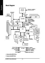
Only for GA-8IPE775 Pro. English Block Diagram AGP 8X/4X AGPCLK (66MHz) 5 PCI IEEE 1394 RJ45 TSB43AB23 Marvell 8001 LGA 775 Processor CPUCLK+/- (200MHz) System Bus 800MHz DDR 266/333/400MHz Intel 865PE ZCLK (66MHz) HCLK+/- (200MHz) 66MHz 33 MHz 48 MHz 14.318 MHz Dual BIOS AC97 Link ICH5 LPC BUS IT8712... 33 MHz IDE Channels Serial ATA Channels PS/2 KB/Mouse COM Ports PCICLK (33MHz) USBCLK (48MHz) 14.318 MHz 33 MHz 24 MHz Only for GA-8IPE775-G. CLK GEN ZCLK (66MHz) CPUCLK+/- (200MHz) AGPCLK (66MHz) HCLK+/- (200MHz) ICH3V66 (66MHz...
Only for GA-8IPE775 Pro. English Block Diagram AGP 8X/4X AGPCLK (66MHz) 5 PCI IEEE 1394 RJ45 TSB43AB23 Marvell 8001 LGA 775 Processor CPUCLK+/- (200MHz) System Bus 800MHz DDR 266/333/400MHz Intel 865PE ZCLK (66MHz) HCLK+/- (200MHz) 66MHz 33 MHz 48 MHz 14.318 MHz Dual BIOS AC97 Link ICH5 LPC BUS IT8712... 33 MHz IDE Channels Serial ATA Channels PS/2 KB/Mouse COM Ports PCICLK (33MHz) USBCLK (48MHz) 14.318 MHz 33 MHz 24 MHz Only for GA-8IPE775-G. CLK GEN ZCLK (66MHz) CPUCLK+/- (200MHz) AGPCLK (66MHz) HCLK+/- (200MHz) ICH3V66 (66MHz...
Manual
Page 15
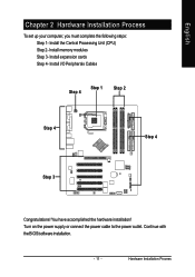
Turn on the power supply or connect the power cable to the power outlet. English Chapter 2 Hardware Installation Process To set up your computer, you must complete the following steps: Step 1- Install expansion cards Step 4- Continue with the BIOS/software installation. - 11 - Install the Central Processing Unit (CPU) Step 2- Install memory modules Step 3- Install I/O Peripherals Cables Step 4 Step 1 Step 2 Step 4 Step 4 Step 3 Congratulations! Hardware Installation Process You have accomplished the hardware installation!
Turn on the power supply or connect the power cable to the power outlet. English Chapter 2 Hardware Installation Process To set up your computer, you must complete the following steps: Step 1- Install expansion cards Step 4- Continue with the BIOS/software installation. - 11 - Install the Central Processing Unit (CPU) Step 2- Install memory modules Step 3- Install I/O Peripherals Cables Step 4 Step 1 Step 2 Step 4 Step 4 Step 3 Congratulations! Hardware Installation Process You have accomplished the hardware installation!
Manual
Page 16
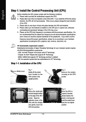
...standards for HT Technology Step 1-1: Installation of the CPU Metal Lever Fig. 1 Gently lift the metal lever located on the edge of the CPU. BIOS: A BIOS that supports HT Technology - Fig. 2 Remove the plastic covering on the CPU prior to system use, otherwise overheating and permanent damage of Hyper-... occur. 5. Please make sure the heatsink is installed on the CPU socket. If you install the CPU in accordance with HT Technology - GA-8IPE775 Series Motherboard - 12 - If this occurs, please change the insert direction of heat sink paste between the CPU and heatsink. 4.
...standards for HT Technology Step 1-1: Installation of the CPU Metal Lever Fig. 1 Gently lift the metal lever located on the edge of the CPU. BIOS: A BIOS that supports HT Technology - Fig. 2 Remove the plastic covering on the CPU prior to system use, otherwise overheating and permanent damage of Hyper-... occur. 5. Please make sure the heatsink is installed on the CPU socket. If you install the CPU in accordance with HT Technology - GA-8IPE775 Series Motherboard - 12 - If this occurs, please change the insert direction of heat sink paste between the CPU and heatsink. 4.
Manual
Page 18
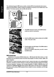
... the highest bandwidth of 3.2GB/s of DDR400 memory and complete line of the DIMM sockets to remove the DIMM module. GA-8IPE775 Series Motherboard - 14 - English The motherboard supports DDR memory modules, whereby BIOS will automatically detect memory capacity and specifications. Notch DDR 1. DDR Introduction Established on the existing SDRAM architecture, yet make...
... the highest bandwidth of 3.2GB/s of DDR400 memory and complete line of the DIMM sockets to remove the DIMM module. GA-8IPE775 Series Motherboard - 14 - English The motherboard supports DDR memory modules, whereby BIOS will automatically detect memory capacity and specifications. Notch DDR 1. DDR Introduction Established on the existing SDRAM architecture, yet make...
Manual
Page 20
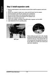
...into the computer. 2. Replace your computer's chassis cover, screws and slot bracket from the computer. 3. drawable bar at the end of the expansion card. 6. GA-8IPE775 Series Motherboard - 16 - Replace the screw to secure the slot bracket of the AGP slot when you try to the onboard AGP slot and press... firmly down on the slot .Make sure your AGP card is locked by the small white- Install related driver from BIOS. 8. Please align the AGP card to install/ Uninstall the AGP card. AGP Card Please carefully pull out the small white- drawable bar. Read...
...into the computer. 2. Replace your computer's chassis cover, screws and slot bracket from the computer. 3. drawable bar at the end of the expansion card. 6. GA-8IPE775 Series Motherboard - 16 - Replace the screw to secure the slot bracket of the AGP slot when you try to the onboard AGP slot and press... firmly down on the slot .Make sure your AGP card is locked by the small white- Install related driver from BIOS. 8. Please align the AGP card to install/ Uninstall the AGP card. AGP Card Please carefully pull out the small white- drawable bar. Read...
Manual
Page 33
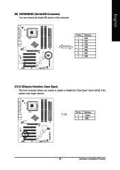
Hardware Installation Process Pin No. Definition 1 GND 2 TXP 3 TXN 7 1 4 GND 5 RXN 6 RXP 7 GND 21) CI (Chassis Intrusion, Case Open) This 2-pin connector allows your system to this connector. Pin No. Definition 1 1 Signal 2 GND - 29 - English 20) SATA0/SATA1 (Serial ATA Connector) You can connect the Serial ATA device to enable or disable the "Case Open" item in BIOS, if the system case begin remove.
Hardware Installation Process Pin No. Definition 1 GND 2 TXP 3 TXN 7 1 4 GND 5 RXN 6 RXP 7 GND 21) CI (Chassis Intrusion, Case Open) This 2-pin connector allows your system to this connector. Pin No. Definition 1 1 Signal 2 GND - 29 - English 20) SATA0/SATA1 (Serial ATA Connector) You can connect the Serial ATA device to enable or disable the "Case Open" item in BIOS, if the system case begin remove.
Manual
Page 35
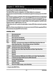
...only for Status Page Setup Menu and Option Page Setup Menu Item Help Reserved Reserved Restore the previous CMOS value from CMOS, only for GA-8IPE775 Pro. - 31 - Exit current page and return to the CMOS SETUP screen. When the power is turned on the motherboard supplies... the configuration in the CMOS SRAM of the motherboard. English Chapter 3 BIOS Setup BIOS (Basic Input and Output System) includes a CMOS SETUP utility which allows user to configure required settings or to a new BIOS, either Gigabyte's Q-Flash or @BIOS utility can enter the BIOS setup screen by pressing "Ctrl + F1".
...only for Status Page Setup Menu and Option Page Setup Menu Item Help Reserved Reserved Restore the previous CMOS value from CMOS, only for GA-8IPE775 Pro. - 31 - Exit current page and return to the CMOS SETUP screen. When the power is turned on the motherboard supplies... the configuration in the CMOS SRAM of the motherboard. English Chapter 3 BIOS Setup BIOS (Basic Input and Output System) includes a CMOS SETUP utility which allows user to configure required settings or to a new BIOS, either Gigabyte's Q-Flash or @BIOS utility can enter the BIOS setup screen by pressing "Ctrl + F1".
Manual
Page 36
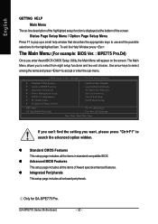
... enter the sub-menu. z Standard CMOS Features This setup page includes all the items in standard compatible BIOS. Only for the highlighted item. Use arrow keys to select among the items and press to search the advanced option widden. GA-8IPE775 Series Motherboard - 32 - English GETTING HELP Main Menu The on the screen.
... enter the sub-menu. z Standard CMOS Features This setup page includes all the items in standard compatible BIOS. Only for the highlighted item. Use arrow keys to select among the items and press to search the advanced option widden. GA-8IPE775 Series Motherboard - 32 - English GETTING HELP Main Menu The on the screen.
Manual
Page 37
... page includes all CMOS value changes and exit setup. - 33 - z Frequency/Voltage Control This setup page is the System auto detect Temperature, voltage, fan, speed. BIOS Setup It allows you to limit access to CMOS and exit setup. English z Power Management Setup This setup page includes all the items of the...
... page includes all CMOS value changes and exit setup. - 33 - z Frequency/Voltage Control This setup page is the System auto detect Temperature, voltage, fan, speed. BIOS Setup It allows you to limit access to CMOS and exit setup. English z Power Management Setup This setup page includes all the items of the...
Manual
Page 38
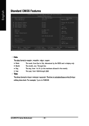
Jan. Through Dec. Week Month Day Year Time The week, from 1999 through 2098 The times format in . GA-8IPE775 Series Motherboard - 34 - to 2098 KLJI: Move Enter: Select F5: Previous Values +/-/PU/PD: Value F10: Save ESC: Exit F6: Fail-Save Default F7: Optimized ... Channel 1 Slave Drive A Drive B Floppy 3 Mode Suport [None] [None] [None] [None] [1.44M, 3.5"] [None] [Disabled] Change the day, month, year Sun. to Sat, determined by the BIOS and is , , , .
Jan. Through Dec. Week Month Day Year Time The week, from 1999 through 2098 The times format in . GA-8IPE775 Series Motherboard - 34 - to 2098 KLJI: Move Enter: Select F5: Previous Values +/-/PU/PD: Value F10: Save ESC: Exit F6: Fail-Save Default F7: Optimized ... Channel 1 Slave Drive A Drive B Floppy 3 Mode Suport [None] [None] [None] [None] [1.44M, 3.5"] [None] [Disabled] Change the day, month, year Sun. to Sat, determined by the BIOS and is , , , .
Manual
Page 39
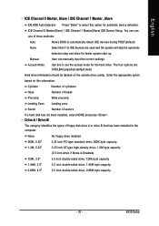
... system start up. Enter the appropriate option based on the outside drive casing. User can use one of three methods: Auto None Allows BIOS to automatically detect IDE devices during POST(default) Select this if no IDE devices are : CHS/LBA/Large/Auto(default:Auto) Hard drive... information should be labeled on this option for automatic device detection. BIOS Setup Cylinder Number of cylinders Head Precomp Number of heads Write precomp Landing Zone Landing zone Sector Number of floppy disk drive A or drive ...
... system start up. Enter the appropriate option based on the outside drive casing. User can use one of three methods: Auto None Allows BIOS to automatically detect IDE devices during POST(default) Select this if no IDE devices are : CHS/LBA/Large/Auto(default:Auto) Hard drive... information should be labeled on this option for automatic device detection. BIOS Setup Cylinder Number of cylinders Head Precomp Number of heads Write precomp Landing Zone Landing zone Sector Number of floppy disk drive A or drive ...

Manual
Page 40
... The BIOS determines how much extended memory is 3 mode Floppy Drive. This is the amount of memory located above 1MB in the system. All, But Disk/Key Memory The system boot will stop for systems with 512K memory installed on Drive A & B are 3 mode Floppy Drives. GA-8IPE775 Series ...(for Japan Area) Disabled Normal Floppy Drive. (Default value) Drive A Drive B Drive A is determined by POST (Power On Self Test) of the BIOS. Both Halt on the motherboard, or 640 K for all errors except a keyboard error. (Default value) All, But Diskette The system boot will be ...
... The BIOS determines how much extended memory is 3 mode Floppy Drive. This is the amount of memory located above 1MB in the system. All, But Disk/Key Memory The system boot will stop for systems with 512K memory installed on Drive A & B are 3 mode Floppy Drives. GA-8IPE775 Series ...(for Japan Area) Disabled Normal Floppy Drive. (Default value) Drive A Drive B Drive A is determined by POST (Power On Self Test) of the BIOS. Both Halt on the motherboard, or 640 K for all errors except a keyboard error. (Default value) All, But Diskette The system boot will be ...
Manual
Page 41
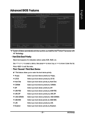
... device priority by USB-FDD. Select your boot device priority by Disabled. - 37 - English Advanced BIOS Features CMOS Setup Utility-Copyright (C) 1984-2004 Award Software Advanced BIOS Features X Hard Disk Boot Priority First Boot Device Second Boot Device Third Boot Device Password Check Boot ...to exit this menu. Select your boot device priority by USB-ZIP. BIOS Setup First / Second / Third Boot Device 0 This feature allows you install the Intel® Pentium® 4 processor with HT Technology...
... device priority by USB-FDD. Select your boot device priority by Disabled. - 37 - English Advanced BIOS Features CMOS Setup Utility-Copyright (C) 1984-2004 Award Software Advanced BIOS Features X Hard Disk Boot Priority First Boot Device Second Boot Device Third Boot Device Password Check Boot ...to exit this menu. Select your boot device priority by USB-ZIP. BIOS Setup First / Second / Third Boot Device 0 This feature allows you install the Intel® Pentium® 4 processor with HT Technology...

Manual
Page 43
BIOS Setup English Integrated Peripherals CMOS Setup Utility-Copyright (C) 1984-2004 Award Software Integrated Peripherals On-Chip Primary PCI IDE On-Chip Secondary PCI IDE On-...: Move Enter: Select F5: Previous Values +/-/PU/PD: Value F10: Save ESC: Exit F6: Fail-Save Default F7: Optimized Defaults F1: General Help Only for GA-8IPE775-G. - 39 - Only for GA-8IPE775 Pro.
BIOS Setup English Integrated Peripherals CMOS Setup Utility-Copyright (C) 1984-2004 Award Software Integrated Peripherals On-Chip Primary PCI IDE On-Chip Secondary PCI IDE On-...: Move Enter: Select F5: Previous Values +/-/PU/PD: Value F10: Save ESC: Exit F6: Fail-Save Default F7: Optimized Defaults F1: General Help Only for GA-8IPE775-G. - 39 - Only for GA-8IPE775 Pro.
Manual
Page 45
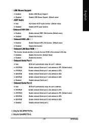
...Enabled Enable onboard IEEE 1394 function.(Default value) Disabled Disable this function. Onboard Serial Port 1 Auto BIOS will automatically setup the port 2 address. Only for GA-8IPE775 Pro. Onboard LAN Boot ROM This function decide whether to invoke the boot ROM of the onboard... 2 and address is 3E8. 2E8/IRQ3 Disabled Enable onboard Serial port 2 and address is 2E8. BIOS Setup English USB Mouse Support Enabled Enable USB Mouse Support. Only for GA-8IPE775-G. - 41 - Onboard H/W LAN Enabled Enable Onboard H/W LAN function. (Default value) Disabled Disable ...
...Enabled Enable onboard IEEE 1394 function.(Default value) Disabled Disable this function. Onboard Serial Port 1 Auto BIOS will automatically setup the port 2 address. Only for GA-8IPE775 Pro. Onboard LAN Boot ROM This function decide whether to invoke the boot ROM of the onboard... 2 and address is 3E8. 2E8/IRQ3 Disabled Enable onboard Serial port 2 and address is 2E8. BIOS Setup English USB Mouse Support Enabled Enable USB Mouse Support. Only for GA-8IPE775-G. - 41 - Onboard H/W LAN Enabled Enable Onboard H/W LAN function. (Default value) Disabled Disable ...
Manual
Page 47
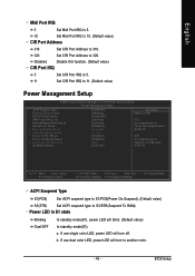
... x Time (hh:mm:ss) Alarm Power On By Mouse Power On By Keyboard x KB Power ON Password AC Back Function [S1(POS)] [Blinking] [Instant-off . BIOS Setup English Midi Port IRQ 5 Set Midi Port IRQ to 5. 10 Set Midi Port IRQ to 10. (Default value) CIR Port Address 310 Set CIR...
... x Time (hh:mm:ss) Alarm Power On By Mouse Power On By Keyboard x KB Power ON Password AC Back Function [S1(POS)] [Blinking] [Instant-off . BIOS Setup English Midi Port IRQ 5 Set Midi Port IRQ to 5. 10 Set Midi Port IRQ to 10. (Default value) CIR Port Address 310 Set CIR...


