Manual
Page 4
... ...6 GA-8I865PE775-G-RH Motherboard Layout 7 Block Diagram ...8 Chapter 1 Hardware Installation 9 1-1 Considerations Prior to Installation 9 1-2 Feature Summary 10 1-3 Installation of the CPU and CPU Cooler 12 1-3-1 Installation of the CPU 12 1-3-2 Installation of the Cooler 13 1-4 Installation of Memory 14 1-5 Installation of Expansion Cards 16 1-6 I/O Back Panel Introduction 17 1-7 Connectors Introduction 18 Chapter 2 BIOS Setup 29 The Main Menu (For example: BIOS Ver. : FBB 30 2-1 Standard CMOS Features 32 2-2 Advanced BIOS Features 34 2-3 IntegratedPeripherals 37 2-4 Power...
... ...6 GA-8I865PE775-G-RH Motherboard Layout 7 Block Diagram ...8 Chapter 1 Hardware Installation 9 1-1 Considerations Prior to Installation 9 1-2 Feature Summary 10 1-3 Installation of the CPU and CPU Cooler 12 1-3-1 Installation of the CPU 12 1-3-2 Installation of the Cooler 13 1-4 Installation of Memory 14 1-5 Installation of Expansion Cards 16 1-6 I/O Back Panel Introduction 17 1-7 Connectors Introduction 18 Chapter 2 BIOS Setup 29 The Main Menu (For example: BIOS Ver. : FBB 30 2-1 Standard CMOS Features 32 2-2 Advanced BIOS Features 34 2-3 IntegratedPeripherals 37 2-4 Power...
Manual
Page 10
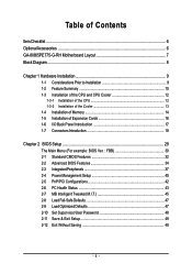
...138; 5 PCI slots Internal Connectors Š 1 24-pin ATX power connector Š 1 4-pin ATX 12V power connector Š 1 floppy connector Š 2 IDE connectors Š 2 SATA connectors Š 1 CPU fan connector Š 1 system fan connector Š 1 front panel connector Š 1 front audio connector Š 1 CD In connector Š 1 AUX In connector Š 1 Surround Center connector Š 1 S/PDIF Out connector Š 1 power LED connector Š 2 USB 2.0/1.1 connectors for additional 4 ports by cables Š 1 Chassis Intrusion connector GA-8I865PE775-G-RH Motherboard...
...138; 5 PCI slots Internal Connectors Š 1 24-pin ATX power connector Š 1 4-pin ATX 12V power connector Š 1 floppy connector Š 2 IDE connectors Š 2 SATA connectors Š 1 CPU fan connector Š 1 system fan connector Š 1 front panel connector Š 1 front audio connector Š 1 CD In connector Š 1 AUX In connector Š 1 Surround Center connector Š 1 S/PDIF Out connector Š 1 power LED connector Š 2 USB 2.0/1.1 connectors for additional 4 ports by cables Š 1 Chassis Intrusion connector GA-8I865PE775-G-RH Motherboard...
Manual
Page 13
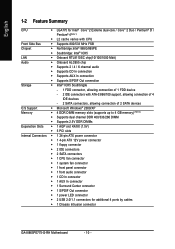
.... (for heat dissipation or using extreme care when removing the CPU cooler. - 13 - Fig. 4 Please make sure the push pins aim to the CPU cooler installation section of the user manual) Fig. 5 Please check the back of motherboard after installing. To prevent such an occurrence, it is complete. Fig. 6 Finally, please attach the power connector of the CPU cooler to install.) Please note the...
.... (for heat dissipation or using extreme care when removing the CPU cooler. - 13 - Fig. 4 Please make sure the push pins aim to the CPU cooler installation section of the user manual) Fig. 5 Please check the back of motherboard after installing. To prevent such an occurrence, it is complete. Fig. 6 Finally, please attach the power connector of the CPU cooler to install.) Please note the...
Manual
Page 20
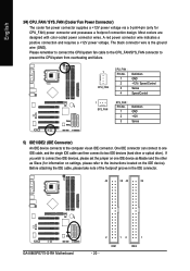
... color-coded power connector wires. If you wish to connect two IDE devices, please set the jumper on one IDE cable, and the single IDE cable can then connect to the instructions located on the IDE device). Before attaching the IDE cable, please take note of the foolproof groove in the IDE connector. 40 39 40 39 GA-8I865PE775-G-RH Motherboard 2 12 1 IDE1 IDE2 - 20 - English 3/4) CPU_FAN / SYS_FAN (Cooler Fan Power Connector) The cooler fan power connector supplies a +12V power voltage via an IDE connector. One IDE connector can connect...
... color-coded power connector wires. If you wish to connect two IDE devices, please set the jumper on one IDE cable, and the single IDE cable can then connect to the instructions located on the IDE device). Before attaching the IDE cable, please take note of the foolproof groove in the IDE connector. 40 39 40 39 GA-8I865PE775-G-RH Motherboard 2 12 1 IDE1 IDE2 - 20 - English 3/4) CPU_FAN / SYS_FAN (Cooler Fan Power Connector) The cooler fan power connector supplies a +12V power voltage via an IDE connector. One IDE connector can connect...

Manual
Page 21
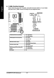
... BIOS setting for the Serial ATA and install the proper driver in the FDD connector. 34 33 2 1 7) SATA0/SATA1 (Serial ATA Connector,) Serial ATA can provide up to 150 MB/s transfer rate. Hardware Installation Before attaching the FDD cable, please take note of the cable connects to work properly. 7 1 SATA0 7 1 SATA1 Pin No. 1 2 3 4 5 6 7 Definition GND TXP TXN GND RXN RXP GND - 21 - The types of FDD drives supported...
... BIOS setting for the Serial ATA and install the proper driver in the FDD connector. 34 33 2 1 7) SATA0/SATA1 (Serial ATA Connector,) Serial ATA can provide up to 150 MB/s transfer rate. Hardware Installation Before attaching the FDD cable, please take note of the cable connects to work properly. 7 1 SATA0 7 1 SATA1 Pin No. 1 2 3 4 5 6 7 Definition GND TXP TXN GND RXN RXP GND - 21 - The types of FDD drives supported...
Manual
Page 22
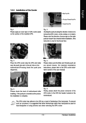
... Connector Power Switch MSG+ MSG- RESRES+ NC Reset Switch IDE Hard Disk Active LED HD (IDE Hard Disk Active LED) (Blue) SPEAK (Speaker Connector) (Amber) RES (Reset Switch) (Green) PW (Power Switch) (Red) MSG(Message LED/Power/Sleep LED) (Yellow) NC ( Purple) Pin 1: LED anode(+) Pin 2: LED cathode(-) Pin 1: Power Pin 2- of your chassis front panel to the F_PANEL connector according to the pin assignments below. Pin 3: NC Pin 4: Data(-) Open: Normal Close: Reset Hardware System Open: Normal Close: Power On/Off Pin 1: LED anode(+) Pin 2: LED cathode(-) NC GA-8I865PE775-G-RH Motherboard...
... Connector Power Switch MSG+ MSG- RESRES+ NC Reset Switch IDE Hard Disk Active LED HD (IDE Hard Disk Active LED) (Blue) SPEAK (Speaker Connector) (Amber) RES (Reset Switch) (Green) PW (Power Switch) (Red) MSG(Message LED/Power/Sleep LED) (Yellow) NC ( Purple) Pin 1: LED anode(+) Pin 2: LED cathode(-) Pin 1: Power Pin 2- of your chassis front panel to the F_PANEL connector according to the pin assignments below. Pin 3: NC Pin 4: Data(-) Open: Normal Close: Reset Hardware System Open: Normal Close: Power On/Off Pin 1: LED anode(+) Pin 2: LED cathode(-) NC GA-8I865PE775-G-RH Motherboard...
Manual
Page 30
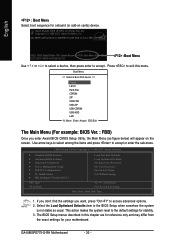
...sub-menu. GA-8I865PE775-G-RH Motherboard - 30 - CMOS Setup Utility-Copyright (C) 1984-2007 Award Software ` Standard CMOS Features ` Advanced BIOS Features ` Integrated Peripherals ` Power Management Setup ` PnP/PCI Configurations ` PC Health Status ` MB Intelligent Tweaker(M.I.T.) Load Fail-Safe Defaults Load Optimized Defaults Set Supervisor Password Set User Password Save & Exit Setup Exit Without Saving ESC: Quit F8: Q-Flash KLJI: Select Item F10: Save & Exit Setup Time, Date, Hard Disk Type... 1. If you don't find the settings you enter Award BIOS CMOS Setup Utility, the Main...
...sub-menu. GA-8I865PE775-G-RH Motherboard - 30 - CMOS Setup Utility-Copyright (C) 1984-2007 Award Software ` Standard CMOS Features ` Advanced BIOS Features ` Integrated Peripherals ` Power Management Setup ` PnP/PCI Configurations ` PC Health Status ` MB Intelligent Tweaker(M.I.T.) Load Fail-Safe Defaults Load Optimized Defaults Set Supervisor Password Set User Password Save & Exit Setup Exit Without Saving ESC: Quit F8: Q-Flash KLJI: Select Item F10: Save & Exit Setup Time, Date, Hard Disk Type... 1. If you don't find the settings you enter Award BIOS CMOS Setup Utility, the Main...
Manual
Page 32
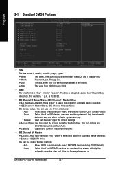
.... GA-8I865PE775-G-RH Motherboard - 32 - IDE Channel 2/3 Master IDE/SATA HDD Auto-Detection Press "Enter" to Sat, determined by the BIOS and is , , , . English 2-1 Standard CMOS Features Date (mm:dd:yy) Time (hh:mm:ss) CMOS Setup Utility-Copyright (C) 1984-2007 Award Software Standard CMOS Features Thu, Mar 1 2007 10:31:24 Item Help Menu Level` ` IDE Channel 0 Master ` IDE Channel 0 Slave ` IDE Channel 1 Master ` IDE Channel 1 Slave ` IDE Channel 2 Master ` IDE Channel 3 Master [None] [None] [None] [None] [None] [None] Drive A Floppy 3 Mode Support [1.44M, 3.5"] [Disabled...
.... GA-8I865PE775-G-RH Motherboard - 32 - IDE Channel 2/3 Master IDE/SATA HDD Auto-Detection Press "Enter" to Sat, determined by the BIOS and is , , , . English 2-1 Standard CMOS Features Date (mm:dd:yy) Time (hh:mm:ss) CMOS Setup Utility-Copyright (C) 1984-2007 Award Software Standard CMOS Features Thu, Mar 1 2007 10:31:24 Item Help Menu Level` ` IDE Channel 0 Master ` IDE Channel 0 Slave ` IDE Channel 1 Master ` IDE Channel 1 Slave ` IDE Channel 2 Master ` IDE Channel 3 Master [None] [None] [None] [None] [None] [None] Drive A Floppy 3 Mode Support [1.44M, 3.5"] [Disabled...
Manual
Page 34
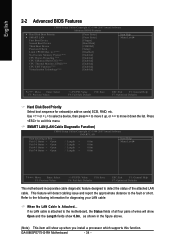
... no LAN cable is attached to the fault or short. SMART LAN (LAN Cable Diagnostic Function) CMOS Setup Utility-Copyright (C) 1984-2007 Award Software SMART LAN Start detecting at Port..... Use < > or < > to select a device, then press to the following information for onboard(or add-on cards) SCSI, RAID, etc. Refer to move it down the list. English 2-2 Advanced BIOS Features CMOS Setup Utility-Copyright (C) 1984-2007 Award Software Advanced BIOS Features ` Hard Disk Boot Priority ` SMART LAN First Boot Device Second Boot Device Third Boot Device Password Check Limit CPUID Max.
... no LAN cable is attached to the fault or short. SMART LAN (LAN Cable Diagnostic Function) CMOS Setup Utility-Copyright (C) 1984-2007 Award Software SMART LAN Start detecting at Port..... Use < > or < > to select a device, then press to the following information for onboard(or add-on cards) SCSI, RAID, etc. Refer to move it down the list. English 2-2 Advanced BIOS Features CMOS Setup Utility-Copyright (C) 1984-2007 Award Software Advanced BIOS Features ` Hard Disk Boot Priority ` SMART LAN First Boot Device Second Boot Device Third Boot Device Password Check Limit CPUID Max.

Manual
Page 35
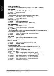
... of the attachedLAN cable. First / Second / Third Boot Device Floppy LS120 Select your boot device priority by Floppy. USB-ZIP Select your boot device priority by USB-ZIP. Hard Disk Select your boot device priority by Hard Disk. USB-FDD Select your boot device priority by USB-FDD. BIOS Setup Note: Pair 4-5 and Pair 7-8 are not used in Windows mode or when the LAN Boot ROM is the approximate length of wires, the Status field will show Short and the length...
... of the attachedLAN cable. First / Second / Third Boot Device Floppy LS120 Select your boot device priority by Floppy. USB-ZIP Select your boot device priority by USB-ZIP. Hard Disk Select your boot device priority by Hard Disk. USB-FDD Select your boot device priority by USB-FDD. BIOS Setup Note: Pair 4-5 and Pair 7-8 are not used in Windows mode or when the LAN Boot ROM is the approximate length of wires, the Status field will show Short and the length...

Manual
Page 37
... Set SATA controller to compatible mode. SATA Port0 Set SATA controller to IDE controller. (Default value) Manual Set SATA mode manually from "SATA Port0 configure as" item. This mode is only supported by Windows XP or later. - 37 - SATA Port0 configure as USB Controller USB 2.0 Controller USB Keyboard Support USB Mouse Support Legacy USB storage detect AC97 Audio Onboard H/W LAN OnBoard LAN Boot ROM Onboard Serial Port 1 Onboard Serial Port 2 Onboard Parallel Port Parallel Port Mode x ECP Mode Use DMA [Enabled] [Enabled] [Auto] SATA Port0 SATA Port1 [Enabled] [Enabled...
... Set SATA controller to compatible mode. SATA Port0 Set SATA controller to IDE controller. (Default value) Manual Set SATA mode manually from "SATA Port0 configure as" item. This mode is only supported by Windows XP or later. - 37 - SATA Port0 configure as USB Controller USB 2.0 Controller USB Keyboard Support USB Mouse Support Legacy USB storage detect AC97 Audio Onboard H/W LAN OnBoard LAN Boot ROM Onboard Serial Port 1 Onboard Serial Port 2 Onboard Parallel Port Parallel Port Mode x ECP Mode Use DMA [Enabled] [Enabled] [Auto] SATA Port0 SATA Port1 [Enabled] [Enabled...
Manual
Page 38
Disable USB keyboard support. (Default value) USB Mouse Support Enabled Enable USB mouse support. OnBoard LAN Boot ROM This function decide whether to detect USB storage devices, including USB flash drives and USB hard drives during POST. GA-8I865PE775-G-RH Motherboard - 38 - Onboard H/W LAN Enabled Enable onboard H/W LAN function. (Default value) Disabled Disable this function. Disabled Disable onboard Serial port 1. AC97 Audio Auto Disabled Enable onboard AC'97 audio function. (Default value) Disable this function. USB 2.0 Controller You can disable this...
Disable USB keyboard support. (Default value) USB Mouse Support Enabled Enable USB mouse support. OnBoard LAN Boot ROM This function decide whether to detect USB storage devices, including USB flash drives and USB hard drives during POST. GA-8I865PE775-G-RH Motherboard - 38 - Onboard H/W LAN Enabled Enable onboard H/W LAN function. (Default value) Disabled Disable this function. Disabled Disable onboard Serial port 1. AC97 Audio Auto Disabled Enable onboard AC'97 audio function. (Default value) Disable this function. USB 2.0 Controller You can disable this...

Manual
Page 44
...pin fan power cable. GA-8I865PE775-G-RH Motherboard - 44 - English CPU Smart FAN Control Disabled Disable this function is enabled. With such CPU fans, selecting PWM will run at different speed depending on their requirements. (Default Value) CPU Smart FAN Mode This option is available only when CPU Smart FAN Control is enabled, CPU fan will not effectively reduce the fan speed. PWM Set to Voltage when you installed and sets the optimal CPU Smart FAN control mode for CPU fans with a 4-pin fan power cable. Auto BIOS autodetects the type of CPU fan you use a CPU...
...pin fan power cable. GA-8I865PE775-G-RH Motherboard - 44 - English CPU Smart FAN Control Disabled Disable this function is enabled. With such CPU fans, selecting PWM will run at different speed depending on their requirements. (Default Value) CPU Smart FAN Mode This option is available only when CPU Smart FAN Control is enabled, CPU fan will not effectively reduce the fan speed. PWM Set to Voltage when you installed and sets the optimal CPU Smart FAN control mode for CPU fans with a 4-pin fan power cable. Auto BIOS autodetects the type of CPU fan you use a CPU...
Manual
Page 45
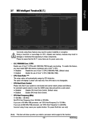
... CMOS Setup Utility-Copyright (C) 1984-2007 Award Software MB Intelligent Tweaker(M.I .T. Doing a overclock or overvoltage on CPU, chipsets and memory modules may result in system instability or corruption. O.C. FSB1066 Core. 2 CPU Enable use a 533 MHz FSB processor, set "CPU Host Frequency" to 133 MHz. CPU Host Frequency (Mhz) 100 MHz ~ 355 MHz Set CPU Host Frequency from 100 MHz to these components. Disabled Disable CPU Host Clock Control. (Default value) Enabled Enable CPU Host Clock Control. If you install a processor which supports this feature, you use...
... CMOS Setup Utility-Copyright (C) 1984-2007 Award Software MB Intelligent Tweaker(M.I .T. Doing a overclock or overvoltage on CPU, chipsets and memory modules may result in system instability or corruption. O.C. FSB1066 Core. 2 CPU Enable use a 533 MHz FSB processor, set "CPU Host Frequency" to 133 MHz. CPU Host Frequency (Mhz) 100 MHz ~ 355 MHz Set CPU Host Frequency from 100 MHz to these components. Disabled Disable CPU Host Clock Control. (Default value) Enabled Enable CPU Host Clock Control. If you install a processor which supports this feature, you use...

Manual
Page 48
... or any time you try to enter Setup Menu. English 2-10 Set Supervisor/User Password CMOS Setup Utility-Copyright (C) 1984-2007 Award Software ` Standard CMOS Features ` Advanced BIOS Features ` Integrated Peripherals ` Power Management Setup ` PnP/PCI ConfiguratioEnsnter Password: ` PC Health Status ` MB Intelligent Tweaker(M.I.T.) Load Fail-Safe Defaults Load Optimized Defaults Set Supervisor Password Set User Password Save & Exit Setup Exit Without Saving ESC: Quit F8: Q-Flash KLJI: Select Item F10: Save & Exit Setup Change/Set/Disable Password When you select this function, the...
... or any time you try to enter Setup Menu. English 2-10 Set Supervisor/User Password CMOS Setup Utility-Copyright (C) 1984-2007 Award Software ` Standard CMOS Features ` Advanced BIOS Features ` Integrated Peripherals ` Power Management Setup ` PnP/PCI ConfiguratioEnsnter Password: ` PC Health Status ` MB Intelligent Tweaker(M.I.T.) Load Fail-Safe Defaults Load Optimized Defaults Set Supervisor Password Set User Password Save & Exit Setup Exit Without Saving ESC: Quit F8: Q-Flash KLJI: Select Item F10: Save & Exit Setup Change/Set/Disable Password When you select this function, the...
Manual
Page 56
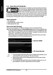
... that Xpress Recovery2 be made by simply pressing the key during system bootup to startup XpressRecovery2..... VESA-supported VGA cards How to use the Xpress Recovery2 Initial access by booting from CD-ROM and subsequent access by booting from CD/DVD: Press any key to back up data on hard disks on . . . Insert the provided driver CD into your hard disk. If you complete installations of system memory 3. GA-8I865PE775-G-RH Motherboard - 56 -
... that Xpress Recovery2 be made by simply pressing the key during system bootup to startup XpressRecovery2..... VESA-supported VGA cards How to use the Xpress Recovery2 Initial access by booting from CD-ROM and subsequent access by booting from CD/DVD: Press any key to back up data on hard disks on . . . Insert the provided driver CD into your hard disk. If you complete installations of system memory 3. GA-8I865PE775-G-RH Motherboard - 56 -
Manual
Page 58
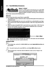
... ENTER. Intel 865PE AGPSet BIOS for 8I865PE775-G-RH PCB 3.0 &4.X FBB . . . . :BIOS Setup/Q-Flash :Xpress Recovery2 :Boot Menu :Qflash 02/27/2007-i865G-6A79ZG0XC-00 : Qflash Because BIOS flashing is potentially risky, please do it with caution and avoid inadequate operation that may result in RAID/AHCI mode or hard drives attached to the independent IDE/SATA controller. b. Extract the downloaded BIOS files and save the new BIOS file (e.g. 65pe75g2.FB) to your motherboard model 2. Q-Flash Utility v2.02 Flash Type/Size...
... ENTER. Intel 865PE AGPSet BIOS for 8I865PE775-G-RH PCB 3.0 &4.X FBB . . . . :BIOS Setup/Q-Flash :Xpress Recovery2 :Boot Menu :Qflash 02/27/2007-i865G-6A79ZG0XC-00 : Qflash Because BIOS flashing is potentially risky, please do it with caution and avoid inadequate operation that may result in RAID/AHCI mode or hard drives attached to the independent IDE/SATA controller. b. Extract the downloaded BIOS files and save the new BIOS file (e.g. 65pe75g2.FB) to your motherboard model 2. Q-Flash Utility v2.02 Flash Type/Size...

Manual
Page 60
... the desired @BIOS server 1. Update BIOS NOT through Internet a. GA-8I865PE775-G-RH Motherboard - 60 - Click "Update New BIOS" icon c. Do not click "Internet Update" icon b. d. English Method 2 : @BIOSTM Utility If you do not have a DOS startup disk, we recommend that you use the new @BIOS utility. @BIOS allows users to download the latest version of BIOS. Just select the desired @BIOS server to update their BIOS under Windows. Installation Complete and Run @BIOS Select @BIOS item Fig...
... the desired @BIOS server 1. Update BIOS NOT through Internet a. GA-8I865PE775-G-RH Motherboard - 60 - Click "Update New BIOS" icon c. Do not click "Internet Update" icon b. d. English Method 2 : @BIOSTM Utility If you do not have a DOS startup disk, we recommend that you use the new @BIOS utility. @BIOS allows users to download the latest version of BIOS. Just select the desired @BIOS server to update their BIOS under Windows. Installation Complete and Run @BIOS Select @BIOS item Fig...

Manual
Page 62
... Audio Configuration menu, click the Speaker Configuration tab and select the 2-channel mode for stereo speaker output check box. Line Out STEP 2: After installing the audio driver, you use speakers with amplifier to install the function. (Following pictures are in Windows® XP) 2 Channel Audio Setup We recommend that you 'll find a Sound Effect icon on the lower right hand taskbar. GA-8I865PE775-G-RH Motherboard - 62 - Click the icon to "Line Out." STEP 1: Connect...
... Audio Configuration menu, click the Speaker Configuration tab and select the 2-channel mode for stereo speaker output check box. Line Out STEP 2: After installing the audio driver, you use speakers with amplifier to install the function. (Following pictures are in Windows® XP) 2 Channel Audio Setup We recommend that you 'll find a Sound Effect icon on the lower right hand taskbar. GA-8I865PE775-G-RH Motherboard - 62 - Click the icon to "Line Out." STEP 1: Connect...

Manual
Page 68
...: System boots successfully 2 short: CMOS setting error 1 long 1 short: DRAM or M/B error 1 long 2 short: Monitor or display card error 1 long 3 short: Keyboard error 1 long 9 short: BIOS ROM error Continuous long beeps: DRAM error Continuous short beeps: Power error GA-8I865PE775-G-RH Motherboard - 68 - Re-insert the battery to the maximum volume? Save changes and reboot the system. Answer: The beep codes below : Steps: 1. Question 3: How do I still get a weak sound after entering BIOS menu and you identify the possible computer problems. However, they are hidden in the manual.
...: System boots successfully 2 short: CMOS setting error 1 long 1 short: DRAM or M/B error 1 long 2 short: Monitor or display card error 1 long 3 short: Keyboard error 1 long 9 short: BIOS ROM error Continuous long beeps: DRAM error Continuous short beeps: Power error GA-8I865PE775-G-RH Motherboard - 68 - Re-insert the battery to the maximum volume? Save changes and reboot the system. Answer: The beep codes below : Steps: 1. Question 3: How do I still get a weak sound after entering BIOS menu and you identify the possible computer problems. However, they are hidden in the manual.


