
Manual
Page 4
...GA-8I848P775-G Motherboard Layout 6 Block Diagram ...7 Chapter 1 Hardware Installation 9 1-1 Considerations Prior to Installation 9 1-2 Feature Summary 10 1-3 Installation of the CPU and Heatsink 12 1-3-1 Installation of the CPU 12 1-3-2 Installation of the Heatsink 13 1-4 Installation of Memory 14 1-5 Installation of Expansion Cards 16 1-6 I/O Back Panel Introduction 17 1-7 Connectors Introduction 18 Chapter 2 BIOS... Setup 29 The Main Menu (For example: BIOS Ver. : E7 30 2-1 Standard CMOS Features 31 2-2 Advanced BIOS Features 34 2-3 ...
...GA-8I848P775-G Motherboard Layout 6 Block Diagram ...7 Chapter 1 Hardware Installation 9 1-1 Considerations Prior to Installation 9 1-2 Feature Summary 10 1-3 Installation of the CPU and Heatsink 12 1-3-1 Installation of the CPU 12 1-3-2 Installation of the Heatsink 13 1-4 Installation of Memory 14 1-5 Installation of Expansion Cards 16 1-6 I/O Back Panel Introduction 17 1-7 Connectors Introduction 18 Chapter 2 BIOS... Setup 29 The Main Menu (For example: BIOS Ver. : E7 30 2-1 Standard CMOS Features 31 2-2 Advanced BIOS Features 34 2-3 ...
Manual
Page 5
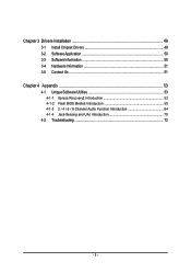
Chapter 3 Drivers Installation 49 3-1 Install Chipset Drivers 49 3-2 SoftwareApplication 50 3-3 Software Information 50 3-4 Hardware Information 51 3-5 Contact Us ...51 Chapter 4 Appendix 53 4-1 Unique Software Utilities 53 4-1-1 Xpress Recovery2 Introduction 53 4-1-2 Flash BIOS Method Introduction 55 4-1-3 2 / 4 / 6 / 8 Channel Audio Function Introduction 64 4-1-4 Jack-Sensing and UAJ Introduction 70 4-2 Troubleshooting 72 - 5 -
Chapter 3 Drivers Installation 49 3-1 Install Chipset Drivers 49 3-2 SoftwareApplication 50 3-3 Software Information 50 3-4 Hardware Information 51 3-5 Contact Us ...51 Chapter 4 Appendix 53 4-1 Unique Software Utilities 53 4-1-1 Xpress Recovery2 Introduction 53 4-1-2 Flash BIOS Method Introduction 55 4-1-3 2 / 4 / 6 / 8 Channel Audio Function Introduction 64 4-1-4 Jack-Sensing and UAJ Introduction 70 4-2 Troubleshooting 72 - 5 -

Manual
Page 6
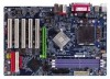
GA-8I848P775-G Motherboard Layout KB_MS USB LGA775 ATX_12V CPU_FAN ATX COMA LPT GA-8I848P775-G DDR1 DDR2 DDR3 COMB LAN USB CLR_CMOS F_AUDIO AUDIO CD_IN Marvell 8001 CODEC SUR_CEN IT8712 CI SPDIF_IO Intel 848P AGP FDD BAT PCI1 ICH5 PCI2 PCI3 BIOS SATA0 SATA1 PCI4 IDE2 IDE1 PCI5 F_USB2 SYS_FAN F_USB1 F_PANEL PWR_LED (Optional) - 6 -
GA-8I848P775-G Motherboard Layout KB_MS USB LGA775 ATX_12V CPU_FAN ATX COMA LPT GA-8I848P775-G DDR1 DDR2 DDR3 COMB LAN USB CLR_CMOS F_AUDIO AUDIO CD_IN Marvell 8001 CODEC SUR_CEN IT8712 CI SPDIF_IO Intel 848P AGP FDD BAT PCI1 ICH5 PCI2 PCI3 BIOS SATA0 SATA1 PCI4 IDE2 IDE1 PCI5 F_USB2 SYS_FAN F_USB1 F_PANEL PWR_LED (Optional) - 6 -

Manual
Page 7
Block Diagram AGP 8X/4X AGPCLK (66MHz) 5 PCI RJ45 Marvell 8001 AC97 Link LGA775 Processor CPUCLK+/-(200/133MHz) Host Interface Intel 848P DDR 266/333/400MHz ZCLK (66MHz) HCLK+/- (133/200MHz) 66MHz 33 MHz 48 MHz 14.318 MHz BIOS ICH5 LPC BUS IT8712 24 MHz Floppy LPT Port PCICLK (33MHz) MIC LINE-IN LINE-OUT AC97 CODEC 8 USB Ports ATA33/66/100 33 MHz IDE Channels Serial ATA Channels PS/2 KB/Mouse COM Ports - 7 -
Block Diagram AGP 8X/4X AGPCLK (66MHz) 5 PCI RJ45 Marvell 8001 AC97 Link LGA775 Processor CPUCLK+/-(200/133MHz) Host Interface Intel 848P DDR 266/333/400MHz ZCLK (66MHz) HCLK+/- (133/200MHz) 66MHz 33 MHz 48 MHz 14.318 MHz BIOS ICH5 LPC BUS IT8712 24 MHz Floppy LPT Port PCICLK (33MHz) MIC LINE-IN LINE-OUT AC97 CODEC 8 USB Ports ATA33/66/100 33 MHz IDE Channels Serial ATA Channels PS/2 KB/Mouse COM Ports - 7 -

Manual
Page 11
Hardware Installation English Hardware Monitor BIOS Additional Features Overclocking Form Factor Š System voltage detection Š CPU temperature detection Š CPU / System fan speed detection Š CPU warning temperature Š CPU / System fan failure warning Š CPU smart fan control Š Use of licensed AWARD BIOS Š Supports Q-Flash Š Supports @BIOS Š Supports EasyTune (only supports Hardware Monitor function) Š Over Voltage via BIOS (CPU/DDR/AGP) Š Over Clock via BIOS (CPU/DDR/AGP/PCI) Š ATX form factor; 30.5cm x 20.5cm - 11 -
Hardware Installation English Hardware Monitor BIOS Additional Features Overclocking Form Factor Š System voltage detection Š CPU temperature detection Š CPU / System fan speed detection Š CPU warning temperature Š CPU / System fan failure warning Š CPU smart fan control Š Use of licensed AWARD BIOS Š Supports Q-Flash Š Supports @BIOS Š Supports EasyTune (only supports Hardware Monitor function) Š Over Voltage via BIOS (CPU/DDR/AGP) Š Over Clock via BIOS (CPU/DDR/AGP/PCI) Š ATX form factor; 30.5cm x 20.5cm - 11 -

Manual
Page 12
...Enabling the functionality of Hyper-Threading Technology for your computer system requires all of the CPU with the following platform components: - BIOS: A BIOS that might cause damage to system use, otherwise overheating and permanent damage of heat sink paste between your hardware specifications including the... of the CPU Metal Lever Fig. 1 Gently lift the metal lever located on the CPU prior to the CPU during installation.) GA-8I848P775-G Motherboard - 12 - CPU: An Intel® Pentium 4 Processor with the processor specifications. Please make sure the heatsink is properly...
...Enabling the functionality of Hyper-Threading Technology for your computer system requires all of the CPU with the following platform components: - BIOS: A BIOS that might cause damage to system use, otherwise overheating and permanent damage of heat sink paste between your hardware specifications including the... of the CPU Metal Lever Fig. 1 Gently lift the metal lever located on the CPU prior to the CPU during installation.) GA-8I848P775-G Motherboard - 12 - CPU: An Intel® Pentium 4 Processor with the processor specifications. Please make sure the heatsink is properly...
Manual
Page 14
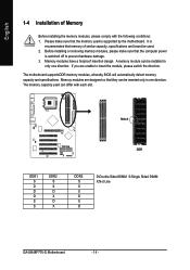
.... The motherboard supportsDDR memory modules, whereby BIOS will automatically detect memory capacity and specifications. Please make sure that the computer power is switched off to insert the module, please switch the direction. Notch DDR DDR1 S D D D S S DDR2 S S D X D X DDR3 S S X D X D D:Double Sided DIMM S:Single Sided DIMM X:Not Use GA-8I848P775-G Motherboard - 14 - If you are designed...
.... The motherboard supportsDDR memory modules, whereby BIOS will automatically detect memory capacity and specifications. Please make sure that the computer power is switched off to insert the module, please switch the direction. Notch DDR DDR1 S D D D S S DDR2 S S D X D X DDR3 S S X D X D D:Double Sided DIMM S:Single Sided DIMM X:Not Use GA-8I848P775-G Motherboard - 14 - If you are designed...
Manual
Page 16
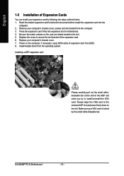
... the VGA card. Press the expansion card firmly into the computer. 2. Please align the VGA card to secure the slot bracket of expansion card from BIOS. 8. GA-8I848P775-G Motherboard - 16 - Be sure the metal contacts on the slot. Remove your VGA card is locked by following the steps outlined below: 1. Installing a AGP expansion... on the card are indeed seated in motherboard. 4. Replace your expansion card by the small white-drawable bar. Power on the computer, if necessary, setup BIOS utility of the expansion card. 6.
... the VGA card. Press the expansion card firmly into the computer. 2. Please align the VGA card to secure the slot bracket of expansion card from BIOS. 8. GA-8I848P775-G Motherboard - 16 - Be sure the metal contacts on the slot. Remove your VGA card is locked by following the steps outlined below: 1. Installing a AGP expansion... on the card are indeed seated in motherboard. 4. Replace your expansion card by the small white-drawable bar. Power on the computer, if necessary, setup BIOS utility of the expansion card. 6.

Manual
Page 21
Pin No. Hardware Installation Please refer to the BIOS setting for information on settings, please refer to the instructions located on one IDE cable, and the single IDE cable can provide up to two ...
Pin No. Hardware Installation Please refer to the BIOS setting for information on settings, please refer to the instructions located on one IDE cable, and the single IDE cable can provide up to two ...

Manual
Page 25
... the cable and connector will make the device unable to detect if the chassis cover is removed. You can check the "Case Opened" status in BIOS Setup. For optional front USB cable, please contact your system to work or even damage it.
... the cable and connector will make the device unable to detect if the chassis cover is removed. You can check the "Case Opened" status in BIOS Setup. For optional front USB cable, please contact your system to work or even damage it.
Manual
Page 29
... a Windows-based utility that you wish to upgrade to a new BIOS, either Gigabyte's Q-Flash or @BIOS utility can enter the BIOS setup screen by pressing "Ctrl + F1". Q-Flash allows the user to quickly and easily update or backup BIOS without entering the operating system. @BIOS is turned off, the battery on , pushing the button during the...
... a Windows-based utility that you wish to upgrade to a new BIOS, either Gigabyte's Q-Flash or @BIOS utility can enter the BIOS setup screen by pressing "Ctrl + F1". Q-Flash allows the user to quickly and easily update or backup BIOS without entering the operating system. @BIOS is turned off, the battery on , pushing the button during the...
Manual
Page 30
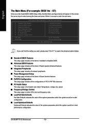
... Defaults Set Supervisor Password Set User Password Save & Exit Setup Exit Without Saving KLJI: Select Item F10: Save & Exit Setup Time, Date, Hard Disk Type... GA-8I848P775-G Motherboard - 30 - English The Main Menu (For example: BIOS Ver. : E7) Once you want, please press "Ctrl+F1" to accept or enter the sub-menu.
... Defaults Set Supervisor Password Set User Password Save & Exit Setup Exit Without Saving KLJI: Select Item F10: Save & Exit Setup Time, Date, Hard Disk Type... GA-8I848P775-G Motherboard - 30 - English The Main Menu (For example: BIOS Ver. : E7) Once you want, please press "Ctrl+F1" to accept or enter the sub-menu.

Manual
Page 31
...:00:00. - 31 - It allows you to limit access to the system. „ Save & Exit Setup Save CMOS value settings to Sat, determined by the BIOS and is , , , . It allows you to limit access to the system and Setup, or just to 31 (or maximum allowed in . to Dec. 1 to Setup... Memory Total Memory KLJI: Move Enter: Select F5: Previous Values 640K 127M 128M +/-/PU/PD: Value F6: Fail-Safe Defaults F10: Save 1999 to Sat. BIOS Setup
...:00:00. - 31 - It allows you to limit access to the system. „ Save & Exit Setup Save CMOS value settings to Sat, determined by the BIOS and is , , , . It allows you to limit access to the system and Setup, or just to 31 (or maximum allowed in . to Dec. 1 to Setup... Memory Total Memory KLJI: Move Enter: Select F5: Previous Values 640K 127M 128M +/-/PU/PD: Value F6: Fail-Safe Defaults F10: Save 1999 to Sat. BIOS Setup

Manual
Page 32
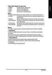
...be labeled on this information. Manual User can use one of floppy disk drive A or drive B that has been installed in the computer. GA-8I848P775-G Motherboard - 32 - Access Mode Use this to set the access mode for the hard drive. Enter the appropriate option based on the ...Write precomp Landing Zone Landing zone Sector Number of sectors Drive A / Drive B The category identifies the types of two methods: Auto Allows BIOS to automatically detect SATA IDE devices during POST(default) None Select this if no SATA IDE devices are : Large/Auto(default:Auto) Capacity ...
...be labeled on this information. Manual User can use one of floppy disk drive A or drive B that has been installed in the computer. GA-8I848P775-G Motherboard - 32 - Access Mode Use this to set the access mode for the hard drive. Enter the appropriate option based on the ...Write precomp Landing Zone Landing zone Sector Number of sectors Drive A / Drive B The category identifies the types of two methods: Auto Allows BIOS to automatically detect SATA IDE devices during POST(default) None Select this if no SATA IDE devices are : Large/Auto(default:Auto) Capacity ...
Manual
Page 33
...stop for all other errors. Base Memory The POST of base (or conventional) memory installed in the CPU's memory address map. Extended Memory The BIOS determines how much extended memory is determined by POST (Power On Self Test) of memory located above 1 MB in the system. Memory The ... will stop for a keyboard error; it will not stop for a keyboard or disk error; Halt on the motherboard. All Errors Whenever the BIOS detects a non-fatal error the system will stop if an error is detected during the POST. The system boot will stop for all other ...
...stop for all other errors. Base Memory The POST of base (or conventional) memory installed in the CPU's memory address map. Extended Memory The BIOS determines how much extended memory is determined by POST (Power On Self Test) of memory located above 1 MB in the system. Memory The ... will stop for a keyboard error; it will not stop for a keyboard or disk error; Halt on the motherboard. All Errors Whenever the BIOS detects a non-fatal error the system will stop if an error is detected during the POST. The system boot will stop for all other ...

Manual
Page 34
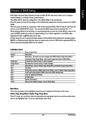
... CMOS Setup Utility-Copyright (C) 1984-2005 Award Software Advanced BIOS Features X Hard Disk Boot Priority First Boot Device Second Boot Device Third Boot Device Password Check # CPU Hyper-Threading Limit CPUID Max. Hard Disk Boot ... want to cancel the setting of password, please just press ENTER to exit this function. USB-FDD Select your boot device priority by USB-FDD. GA-8I848P775-G Motherboard - 34 - Password Check Setup The system will boot but will not access to Setup page if the correct password is not entered at the...
... CMOS Setup Utility-Copyright (C) 1984-2005 Award Software Advanced BIOS Features X Hard Disk Boot Priority First Boot Device Second Boot Device Third Boot Device Password Check # CPU Hyper-Threading Limit CPUID Max. Hard Disk Boot ... want to cancel the setting of password, please just press ENTER to exit this function. USB-FDD Select your boot device priority by USB-FDD. GA-8I848P775-G Motherboard - 34 - Password Check Setup The system will boot but will not access to Setup page if the correct password is not entered at the...

Manual
Page 35
... use older OS like NT4. to 3 Enabled Limit CPUID Maximum value to IDE controller. (Default value) Manual Set SATA Mode manually. - 35 - Limit CPUID Max. BIOS Setup
... use older OS like NT4. to 3 Enabled Limit CPUID Maximum value to IDE controller. (Default value) Manual Set SATA Mode manually. - 35 - Limit CPUID Max. BIOS Setup

Manual
Page 36
... 1 Auto BIOS will automatically setup the port 1 address. 3F8/IRQ4 2F8/IRQ3 Enable onboard Serial port 1 and address is 3F8/IRQ4. (Default value) Enable onboard Serial port 1 and address is 2F8/IRQ3. 3E8/IRQ4 2E8/IRQ3 Enable onboard Serial port 1 and address is 2E8/IRQ3. Disabled Disable onboard Serial port 1. GA-8I848P775-G Motherboard...
... 1 Auto BIOS will automatically setup the port 1 address. 3F8/IRQ4 2F8/IRQ3 Enable onboard Serial port 1 and address is 3F8/IRQ4. (Default value) Enable onboard Serial port 1 and address is 2F8/IRQ3. 3E8/IRQ4 2E8/IRQ3 Enable onboard Serial port 1 and address is 2E8/IRQ3. Disabled Disable onboard Serial port 1. GA-8I848P775-G Motherboard...

Manual
Page 37
... and address is 278/IRQ5. 3BC/IRQ7 Enable onboard LPT port and address is 2E8/IRQ3. ECP+EPP Using Parallel port as ECP & EPP mode. BIOS Setup ECP Mode Use DMA 3 Set ECP Mode Use DMA to 3. (Default value) 1 Set ECP Mode Use DMA to 1. - 37 - English Onboard Serial Port 2 Auto... BIOS will automatically setup the port 2 address. 3F8/IRQ4 Enable onboard Serial port 2 and address is 3F8/IRQ4. 2F8/IRQ3 Enable onboard Serial port 2 and address ...
... and address is 278/IRQ5. 3BC/IRQ7 Enable onboard LPT port and address is 2E8/IRQ3. ECP+EPP Using Parallel port as ECP & EPP mode. BIOS Setup ECP Mode Use DMA 3 Set ECP Mode Use DMA to 3. (Default value) 1 Set ECP Mode Use DMA to 1. - 37 - English Onboard Serial Port 2 Auto... BIOS will automatically setup the port 2 address. 3F8/IRQ4 Enable onboard Serial port 2 and address is 3F8/IRQ4. 2F8/IRQ3 Enable onboard Serial port 2 and address ...

Manual
Page 39
... this function. (Default value) Double click on PS/2 mouse left button to set the password here. Enabled Enable Modem Ring on/wake on the system. BIOS Setup Enter Input password (from 1 to 5 characters to set "Resume by Alarm" item to power on the system. Memory When AC-power back to the...
... this function. (Default value) Double click on PS/2 mouse left button to set the password here. Enabled Enable Modem Ring on/wake on the system. BIOS Setup Enter Input password (from 1 to 5 characters to set "Resume by Alarm" item to power on the system. Memory When AC-power back to the...


