
User Manual
Page 6
English Table of Content Item Checklist 4 Chapter 1 Introduction 5 Features Summary 5 GA-8I848P(-G) Motherboard Layout 7 Block Diagram 8 Chapter 2 Hardware Installation Process 10 Step 1: Install the Central Processing Unit (CPU 11 Step 1-1: CPU... cabinet wires, and power supply 16 Step 4-1: I/O Back Panel Introduction 16 Step 4-2: Connectors & Jumper Setting Introduction 18 Chapter 3 BIOS Setup 31 The Main Menu (For example: BIOS Ver. : E1 32 Standard CMOS Features 34 Advanced BIOS Features 37 Integrated Peripherals 39 Power Management Setup 44 GA-8I848P(-G) Motherboard - 2 -
English Table of Content Item Checklist 4 Chapter 1 Introduction 5 Features Summary 5 GA-8I848P(-G) Motherboard Layout 7 Block Diagram 8 Chapter 2 Hardware Installation Process 10 Step 1: Install the Central Processing Unit (CPU 11 Step 1-1: CPU... cabinet wires, and power supply 16 Step 4-1: I/O Back Panel Introduction 16 Step 4-2: Connectors & Jumper Setting Introduction 18 Chapter 3 BIOS Setup 31 The Main Menu (For example: BIOS Ver. : E1 32 Standard CMOS Features 34 Advanced BIOS Features 37 Integrated Peripherals 39 Power Management Setup 44 GA-8I848P(-G) Motherboard - 2 -

User Manual
Page 7
Channel Audio Function Introduction 74 Jack-Sensing(UAJ) Introduction 80 Xpress Recovery2 Introduction 82 Chapter 5 Appendix 85 - 3 - English PnP/PCI Configurations 46 PC Health Status 47 Frequency/Voltage Control 49 Load Fail-Safe Defaults 52 Load Optimized Defaults 53 Set Supervisor/User Password 54 Save & Exit Setup 55 Exit Without Saving 56 Chapter 4 Technical Reference 57 @ BIOSTM Introduction 57 Easy TuneTM 4 Introduction 58 Flash BIOS Method Introduction 59 2- / 4- / 6- / 8- Table of Content
Channel Audio Function Introduction 74 Jack-Sensing(UAJ) Introduction 80 Xpress Recovery2 Introduction 82 Chapter 5 Appendix 85 - 3 - English PnP/PCI Configurations 46 PC Health Status 47 Frequency/Voltage Control 49 Load Fail-Safe Defaults 52 Load Optimized Defaults 53 Set Supervisor/User Password 54 Save & Exit Setup 55 Exit Without Saving 56 Chapter 4 Technical Reference 57 @ BIOSTM Introduction 57 Easy TuneTM 4 Introduction 58 Flash BIOS Method Introduction 59 2- / 4- / 6- / 8- Table of Content
User Manual
Page 10
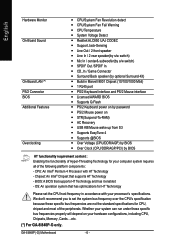
GA-8I848P(-G) Motherboard - 6 - English Hardware Monitor On-Board Sound On-Board LAN (*) PS/2 Connector BIOS Additional Features Overclocking y CPU/System Fan Revolution detect y CPU/System Fan Fail Warning y CPU Temperature y System Voltage Detect y ...computer system requires all of the peripherals. BIOS: A BIOS that supports HT Technology - Whether your system can run under these specific bus frequencies are not the standard specifications for your hardware configurations, including CPU, Chipsets, Memory, Cards....etc. (*) For GA-8I848P-G only. CPU: An Intel® Pentium...
GA-8I848P(-G) Motherboard - 6 - English Hardware Monitor On-Board Sound On-Board LAN (*) PS/2 Connector BIOS Additional Features Overclocking y CPU/System Fan Revolution detect y CPU/System Fan Fail Warning y CPU Temperature y System Voltage Detect y ...computer system requires all of the peripherals. BIOS: A BIOS that supports HT Technology - Whether your system can run under these specific bus frequencies are not the standard specifications for your hardware configurations, including CPU, Chipsets, Memory, Cards....etc. (*) For GA-8I848P-G only. CPU: An Intel® Pentium...
User Manual
Page 11
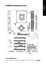
Introduction English GA-8I848P(-G) Motherboard Layout KB_MS USB COMA ATX_12V SOCKET478 CPU_FAN ATX FDD COMB LPT GA-8I848P-G Hyper Threading DDR1 DDR2 DDR3 MIC_IN USB LINE_OUT LINE_IN LAN (*) F_AUDIO CD_IN Intel® 848P Marvell 8001 (*) AGP 8X AGP BAT CLR_CMOS CODEC SUR_CEN ITE8712 GAME ICH5 PCI1 SATA PCI2 P4 Titan BIOS PCI3 SATA0 SATA1 CI IR SPDIF_IO PCI4 PCI5 INFO_LINK F_USB2 F_USB1 IDE2 IDE1 SYS_FAN F_PANEL PWR_LED (*) For GA-8I848P-G only. - 7 -
Introduction English GA-8I848P(-G) Motherboard Layout KB_MS USB COMA ATX_12V SOCKET478 CPU_FAN ATX FDD COMB LPT GA-8I848P-G Hyper Threading DDR1 DDR2 DDR3 MIC_IN USB LINE_OUT LINE_IN LAN (*) F_AUDIO CD_IN Intel® 848P Marvell 8001 (*) AGP 8X AGP BAT CLR_CMOS CODEC SUR_CEN ITE8712 GAME ICH5 PCI1 SATA PCI2 P4 Titan BIOS PCI3 SATA0 SATA1 CI IR SPDIF_IO PCI4 PCI5 INFO_LINK F_USB2 F_USB1 IDE2 IDE1 SYS_FAN F_PANEL PWR_LED (*) For GA-8I848P-G only. - 7 -

User Manual
Page 12
...) System Bus 400/533/800MHz Intel 848P DDR 266/333/400MHz ZCLK (66MHz) HCLK+/- (100/133/200MHz) 66MHz 33 MHz 48 MHz 14.318 MHz BIOS AC97 Link ICH5 LPC BUS ITE8712 24 MHz Game Port Floppy LPT Port PCICLK (33MHz) MIC LINE-IN LINE-OUT AC97 CODEC 8 USB (2.0/1.1) Ports ATA33.../100 IDE Channels 33 MHz Serial ATA Channels PS/2 KB/Mouse COM Ports PCICLK (33MHz) USBCLK (48MHz) 14.318 MHz 33 MHz 24 MHz (*) For GA-8I848P-G only. ZCLK (66MHz) CPUCLK+/- (100/133/200MHz) AGPCLK (66MHz) HCLK+/- (100/133/200MHz) ICH3V66 (66MHz...
...) System Bus 400/533/800MHz Intel 848P DDR 266/333/400MHz ZCLK (66MHz) HCLK+/- (100/133/200MHz) 66MHz 33 MHz 48 MHz 14.318 MHz BIOS AC97 Link ICH5 LPC BUS ITE8712 24 MHz Game Port Floppy LPT Port PCICLK (33MHz) MIC LINE-IN LINE-OUT AC97 CODEC 8 USB (2.0/1.1) Ports ATA33.../100 IDE Channels 33 MHz Serial ATA Channels PS/2 KB/Mouse COM Ports PCICLK (33MHz) USBCLK (48MHz) 14.318 MHz 33 MHz 24 MHz (*) For GA-8I848P-G only. ZCLK (66MHz) CPUCLK+/- (100/133/200MHz) AGPCLK (66MHz) HCLK+/- (100/133/200MHz) ICH3V66 (66MHz...
User Manual
Page 14
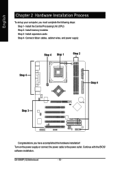
Install memory modules Step 3- Connect ribbon cables, cabinet wires, and power supply Step 4 Step 1 Step 2 Step 4 Step 4 Step 3 Congratulations you must complete the following steps: Step 1- Install expansion cards Step 4- Turn on the power supply or connect the power cable to the power outlet. Continue with the BIOS/ software installation. English Chapter 2 Hardware Installation Process To set up your computer, you have accomplished the hardware installation! GA-8I848P(-G) Motherboard - 10 - Install the Central Processing Unit (CPU) Step 2-
Install memory modules Step 3- Connect ribbon cables, cabinet wires, and power supply Step 4 Step 1 Step 2 Step 4 Step 4 Step 3 Congratulations you must complete the following steps: Step 1- Install expansion cards Step 4- Turn on the power supply or connect the power cable to the power outlet. Continue with the BIOS/ software installation. English Chapter 2 Hardware Installation Process To set up your computer, you have accomplished the hardware installation! GA-8I848P(-G) Motherboard - 10 - Install the Central Processing Unit (CPU) Step 2-

User Manual
Page 17
The BIOS will cause improper installation. Hardware Installation Process Memory size can vary between sockets. The motherboard has 3 dual inline memory module (DIMM) sockets. To install the ...
The BIOS will cause improper installation. Hardware Installation Process Memory size can vary between sockets. The motherboard has 3 dual inline memory module (DIMM) sockets. To install the ...

User Manual
Page 19
Be sure the metal contacts on the computer, if necessary, setup BIOS utility of expansion card from BIOS. 8. Install related driver from the computer. 3. drawable bar at the end of the expansion card. 6. Please align the AGP card to install/ Uninstall the AGP ...
Be sure the metal contacts on the computer, if necessary, setup BIOS utility of expansion card from BIOS. 8. Install related driver from the computer. 3. drawable bar at the end of the expansion card. 6. Please align the AGP card to install/ Uninstall the AGP ...

User Manual
Page 32
Pin No. Definition 1 1 Signal 2 GND GA-8I848P(-G) Motherboard - 28 - English 18) SATA0/SATA1 (Serial ATA Connector) You can connect the Serial ATA device to this connector, it provides you high speed transfer rates (150MB/sec). 17 Pin No. 1 2 3 4 5 6 7 Definition GND TXP TXN GND RXN RXP GND 19) CI (CASE OPEN) This 2 pin connector allows your system to enable or disable the "case open" item in BIOS if the system case begin remove.
Pin No. Definition 1 1 Signal 2 GND GA-8I848P(-G) Motherboard - 28 - English 18) SATA0/SATA1 (Serial ATA Connector) You can connect the Serial ATA device to this connector, it provides you high speed transfer rates (150MB/sec). 17 Pin No. 1 2 3 4 5 6 7 Definition GND TXP TXN GND RXN RXP GND 19) CI (CASE OPEN) This 2 pin connector allows your system to enable or disable the "case open" item in BIOS if the system case begin remove.

User Manual
Page 35
... Page Setup Menu and Option Page Setup Menu - Exit current page and return to modify the basic system configuration. English Chapter 3 BIOS Setup BIOS Setup is turned off. This type of information is stored in battery-backed CMOS RAM so that allows users to Main Menu Increase ...Help Reserved Reserved Restore the previous CMOS value from CMOS, only for Option Page Setup Menu Load the file-safe default CMOS value from BIOS default table Load the Optimized Defaults Q-Flash function System Information Save all the CMOS changes, only for Main Menu - 31 - The program...
... Page Setup Menu and Option Page Setup Menu - Exit current page and return to modify the basic system configuration. English Chapter 3 BIOS Setup BIOS Setup is turned off. This type of information is stored in battery-backed CMOS RAM so that allows users to Main Menu Increase ...Help Reserved Reserved Restore the previous CMOS value from CMOS, only for Option Page Setup Menu Load the file-safe default CMOS value from BIOS default table Load the Optimized Defaults Q-Flash function System Information Save all the CMOS changes, only for Main Menu - 31 - The program...

User Manual
Page 36
...to select from eight setup functions and two exit choices. Figure 1: Main Menu If you can't find the setting you enter Award BIOS CMOS Setup Utility, the Main Menu (Figure 1) will appear on -line description of the highlighted setup function is displayed at the ... among the items and press to use and the possible selections for the highlighted item. GA-8I848P(-G) Motherboard - 32 - z Advanced BIOS Features This setup page includes all the items in standard compatible BIOS. CMOS Setup Utility-Copyright (C) 1984-2004 Award Software Standard CMOS Features Load Fail-Safe ...
...to select from eight setup functions and two exit choices. Figure 1: Main Menu If you can't find the setting you enter Award BIOS CMOS Setup Utility, the Main Menu (Figure 1) will appear on -line description of the highlighted setup function is displayed at the ... among the items and press to use and the possible selections for the highlighted item. GA-8I848P(-G) Motherboard - 32 - z Advanced BIOS Features This setup page includes all the items in standard compatible BIOS. CMOS Setup Utility-Copyright (C) 1984-2004 Award Software Standard CMOS Features Load Fail-Safe ...

User Manual
Page 37
... disable password. z Set Supervisor password Change, set , or disable password. It allows you to limit access to the system and Setup, or just to Setup. BIOS Setup z Power Management Setup This setup page includes all onboard peripherals. z Frequency/Voltage Control This setup page is the System auto detect Temperature, voltage, fan...
... disable password. z Set Supervisor password Change, set , or disable password. It allows you to limit access to the system and Setup, or just to Setup. BIOS Setup z Power Management Setup This setup page includes all onboard peripherals. z Frequency/Voltage Control This setup page is the System auto detect Temperature, voltage, fan...

User Manual
Page 38
... Extended Memory Total Memory [1.44M, 3.5 in the month) The year, from Sun to Sat. Week Month Day Year The week, from 1999 through 2098 GA-8I848P(-G) Motherboard - 34 - to Dec. 1 to 31 (or maximum allowed in the month) 1999 to 2098 : Move Enter:Select +/-/PU/PD:Value F10...1 to 31 (or the maximum allowed in .] [None] [Disabled] [All, But Keyboard] 640K 130048K 131072K Jan. Through Dec. to Sat, determined by the BIOS and is , , , . English Standard CMOS Features CMOS Setup Utility-Copyright (C) 1984-2004 Award Software Date (mm:dd:yy) Time (hh:mm:ss) Standard CMOS...
... Extended Memory Total Memory [1.44M, 3.5 in the month) The year, from Sun to Sat. Week Month Day Year The week, from 1999 through 2098 GA-8I848P(-G) Motherboard - 34 - to Dec. 1 to 31 (or maximum allowed in the month) 1999 to 2098 : Move Enter:Select +/-/PU/PD:Value F10...1 to 31 (or the maximum allowed in .] [None] [Disabled] [All, But Keyboard] 640K 130048K 131072K Jan. Through Dec. to Sat, determined by the BIOS and is , , , . English Standard CMOS Features CMOS Setup Utility-Copyright (C) 1984-2004 Award Software Date (mm:dd:yy) Time (hh:mm:ss) Standard CMOS...
User Manual
Page 39
...-sided drive; 1.44M byte capacity. 2.88M, 3.5 in the computer. Drive A / Drive B The category identifies the types of your hard disk vendor or the system manufacturer. BIOS Setup There are two types: auto type, and manual type. Such information should be asked to enter to the following items. Enter the information directly...
...-sided drive; 1.44M byte capacity. 2.88M, 3.5 in the computer. Drive A / Drive B The category identifies the types of your hard disk vendor or the system manufacturer. BIOS Setup There are two types: auto type, and manual type. Such information should be asked to enter to the following items. Enter the information directly...

User Manual
Page 40
... is the amount of memory located above 1 MB in the system. This is determined by POST (Power On Self Test) of the BIOS will not stop for all other errors. (Default value) All, But Diskette The system boot will not stop if an error is typically... (or conventional) memory installed in the CPU's memory address map. Extended Memory The BIOS determines how much extended memory is 3 mode Floppy Drive. Drive B Drive B is present during power up. Both Drive A & B are 3 mode Floppy Drives. GA-8I848P(-G) Motherboard - 36 - English Floppy 3 Mode Support (for a keyboard or disk ...
... is the amount of memory located above 1 MB in the system. This is determined by POST (Power On Self Test) of the BIOS will not stop for all other errors. (Default value) All, But Diskette The system boot will not stop if an error is typically... (or conventional) memory installed in the CPU's memory address map. Extended Memory The BIOS determines how much extended memory is 3 mode Floppy Drive. Drive B Drive B is present during power up. Both Drive A & B are 3 mode Floppy Drives. GA-8I848P(-G) Motherboard - 36 - English Floppy 3 Mode Support (for a keyboard or disk ...
User Manual
Page 41
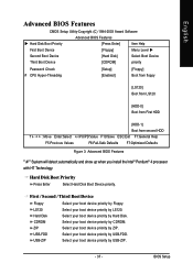
... boot device priority by USB-FDD. ZIP Select your boot device priority by Floppy. English Advanced BIOS Features CMOS Setup Utility-Copyright (C) 1984-2003 Award Software Advanced BIOS Features Hard Disk Boot Priority [Press Enter] Item Help First Boot Device [Floppy] Menu Level ... Enter:Select +/-/PU/PD:Value F10:Save ESC:Exit F1:General Help F5:Previous Values F6:Fail-Safe Defaults F7:Optimized Defaults Figure 3: Advanced BIOS Features " # " System will detect automatically and show up when you install the Intel® Pentium® 4 processor with HT Technology....
... boot device priority by USB-FDD. ZIP Select your boot device priority by Floppy. English Advanced BIOS Features CMOS Setup Utility-Copyright (C) 1984-2003 Award Software Advanced BIOS Features Hard Disk Boot Priority [Press Enter] Item Help First Boot Device [Floppy] Menu Level ... Enter:Select +/-/PU/PD:Value F10:Save ESC:Exit F1:General Help F5:Previous Values F6:Fail-Safe Defaults F7:Optimized Defaults Figure 3: Advanced BIOS Features " # " System will detect automatically and show up when you install the Intel® Pentium® 4 processor with HT Technology....

User Manual
Page 43
BIOS Setup English Integrated Peripherals CMOS Setup Utility-Copyright (C) 1984-2004 Award Software Integrated Peripherals On-Chip Primary PCI IDE [Enabled] Item Help On-Chip Secondary ...:Select +/-/PU/PD:Value F10:Save ESC:Exit F1:General Help F5:Previous Values F6:Fail-Safe Defaults F7:Optimized Defaults Figure 4: Integrated Peripherals (*) For GA-8I848P-G only. - 39 -
BIOS Setup English Integrated Peripherals CMOS Setup Utility-Copyright (C) 1984-2004 Award Software Integrated Peripherals On-Chip Primary PCI IDE [Enabled] Item Help On-Chip Secondary ...:Select +/-/PU/PD:Value F10:Save ESC:Exit F1:General Help F5:Previous Values F6:Fail-Safe Defaults F7:Optimized Defaults Figure 4: Integrated Peripherals (*) For GA-8I848P-G only. - 39 -

User Manual
Page 45
...Default value) Disabled Disable USB 2.0 Controller. USB Keyboard Support Enabled Enable USB Keyboard Support. Disabled Disable onboard Serial port 1. (*) For GA-8I848P-G only. - 41 - Disabled Disable USB Mouse Support. (Default value) AC97 Audio Auto Enable onboard AC'97 audio function. (Default...function. Disabled Disable USB Keyboard Support. (Default value) USB Mouse Support Enabled Enable USB Mouse Support. Onboard Serial Port 1 Auto BIOS will automatically setup the port 1 address. 3F8/IRQ4 Enable onboard Serial port 1 and address is 3F8. (Default value) 2F8...
...Default value) Disabled Disable USB 2.0 Controller. USB Keyboard Support Enabled Enable USB Keyboard Support. Disabled Disable onboard Serial port 1. (*) For GA-8I848P-G only. - 41 - Disabled Disable USB Mouse Support. (Default value) AC97 Audio Auto Enable onboard AC'97 audio function. (Default...function. Disabled Disable USB Keyboard Support. (Default value) USB Mouse Support Enabled Enable USB Mouse Support. Onboard Serial Port 1 Auto BIOS will automatically setup the port 1 address. 3F8/IRQ4 Enable onboard Serial port 1 and address is 3F8. (Default value) 2F8...

User Manual
Page 46
... ASKIR Set onboard I/O chip UART to 1. ECP+EPP Using Parallel port as Enhanced Parallel Port. ECP Using Parallel port as Extended Capabilities Port. GA-8I848P(-G) Motherboard - 42 - Onboard Parallel port 378/IRQ7 278/IRQ5 Enable onboard LPT port and address is 378/IRQ7. (Default value) Enable onboard ...LPT port and address is 3BC/IRQ7. English Onboard Serial Port 2 Auto BIOS will automatically setup the port 2 address. 3F8/IRQ4 Enable onboard Serial port 2 and address is 3F8. 2F8/IRQ3 Enable onboard Serial port ...
... ASKIR Set onboard I/O chip UART to 1. ECP+EPP Using Parallel port as Enhanced Parallel Port. ECP Using Parallel port as Extended Capabilities Port. GA-8I848P(-G) Motherboard - 42 - Onboard Parallel port 378/IRQ7 278/IRQ5 Enable onboard LPT port and address is 378/IRQ7. (Default value) Enable onboard ...LPT port and address is 3BC/IRQ7. English Onboard Serial Port 2 Auto BIOS will automatically setup the port 2 address. 3F8/IRQ4 Enable onboard Serial port 2 and address is 3F8. 2F8/IRQ3 Enable onboard Serial port ...

User Manual
Page 49
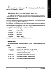
.../wake on the status before AC lost. Disabled Disabled this function. KB Power ON Password Enter Input password (from 1 to 5 characters to set the Key- BIOS Setup English PME Event Wake Up Disabled Disable this function. (Default value) Keyboard 98 If your keyboard have "POWER Key" button, you can set "Resume...
.../wake on the status before AC lost. Disabled Disabled this function. KB Power ON Password Enter Input password (from 1 to 5 characters to set the Key- BIOS Setup English PME Event Wake Up Disabled Disable this function. (Default value) Keyboard 98 If your keyboard have "POWER Key" button, you can set "Resume...


