Manual
Page 4
... GA-73PVM-S2H Motherboard Layout 7 Block Diagram...8 Chapter 1 Hardware Installation 9 1-1 Installation Precautions 9 1-2 Product Specifications 10 1-3 Installing the CPU and CPU Cooler 13 1-3-1 Installing the CPU 13 1-3-2 Installing the CPU Cooler 15 1-4 Installing the Memory 16 1-4-1 Installing a Memory 16 1-5 Installing an Expansion Card 17 1-6 Back Panel Connectors 20 1-7 Internal Connectors 23 Chapter 2 BIOS Setup 35 2-1 Startup Screen 36 2-2 The Main Menu 37 2-3 Standard CMOS Features 39 2-4 Advanced BIOS Features 41 2-5 Integrated Peripherals 43 2-6 Power Management...
... GA-73PVM-S2H Motherboard Layout 7 Block Diagram...8 Chapter 1 Hardware Installation 9 1-1 Installation Precautions 9 1-2 Product Specifications 10 1-3 Installing the CPU and CPU Cooler 13 1-3-1 Installing the CPU 13 1-3-2 Installing the CPU Cooler 15 1-4 Installing the Memory 16 1-4-1 Installing a Memory 16 1-5 Installing an Expansion Card 17 1-6 Back Panel Connectors 20 1-7 Internal Connectors 23 Chapter 2 BIOS Setup 35 2-1 Startup Screen 36 2-2 The Main Menu 37 2-3 Standard CMOS Features 39 2-4 Advanced BIOS Features 41 2-5 Integrated Peripherals 43 2-6 Power Management...
Manual
Page 10
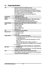
...; High Definition Audio 2/4/5.1/7.1-channel Support for S/PDIF In/Out Support for SATA RAID 0, RAID 1, RAID 5, and RAID 0+1 - 1 x IDE connector supporting ATA-133/100/66/33 and up to 2 IDE devices iTE IT8718 chip: - 1 x floppy disk drive connector supporting up to the internal USB headers) GA-73PVM-S2H Motherboard - 10 - Support for CD In RTL 8211B chip (10/100/1000 Mbit) 1 x PCI Express x16 slot 1 x PCI Express x1 slot 2 x PCI slots nVIDIA® GeForce 7100/nForce 630i chipset: - 3 x SATA 3Gb/s connectors...
...; High Definition Audio 2/4/5.1/7.1-channel Support for S/PDIF In/Out Support for SATA RAID 0, RAID 1, RAID 5, and RAID 0+1 - 1 x IDE connector supporting ATA-133/100/66/33 and up to 2 IDE devices iTE IT8718 chip: - 1 x floppy disk drive connector supporting up to the internal USB headers) GA-73PVM-S2H Motherboard - 10 - Support for CD In RTL 8211B chip (10/100/1000 Mbit) 1 x PCI Express x16 slot 1 x PCI Express x1 slot 2 x PCI slots nVIDIA® GeForce 7100/nForce 630i chipset: - 3 x SATA 3Gb/s connectors...
Manual
Page 17
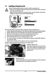
... panel. 2. After installing all expansion cards, replace the chassis cover(s). 6. If necessary, go to BIOS Setup to prevent hardware damage. Example: Installing and Removing a PCI Express x16 Graphics Card: • Installing a Graphics Card: Gently insert the graphics card into the slot. 4. PCI Express x1 Slot PCI Express x16 Slot PCI Slot Follow the steps below to install an expansion card: • Make sure the motherboard supports the expansion card. Align the card with your card. Turn on the card are completely inserted into the PCI Express x16 slot. Install the driver...
... panel. 2. After installing all expansion cards, replace the chassis cover(s). 6. If necessary, go to BIOS Setup to prevent hardware damage. Example: Installing and Removing a PCI Express x16 Graphics Card: • Installing a Graphics Card: Gently insert the graphics card into the slot. 4. PCI Express x1 Slot PCI Express x16 Slot PCI Slot Follow the steps below to install an expansion card: • Make sure the motherboard supports the expansion card. Align the card with your card. Turn on the card are completely inserted into the PCI Express x16 slot. Install the driver...

Manual
Page 20
... the monitor being used. • After installing the HDMI device, make sure the default device for sound playback toNVIDIAHDMIAudioWave. GA-73PVM-S2H Motherboard - 20 - The HDMI Technology can support a maximum resolution of an external decoder for decoding.) In Windows XP, select Start>Control Panel>Sounds and Audio Devices Properties>Audio, set the Default device for sound playback is HDCP compliant. DVI-D Port The DVI-D port supports DVI-D specifictation. D-Sub Port The D-Sub port supports a 15-pin D-Sub connector. In Windows Vista, select Start>Control Panel> Sound, select...
... the monitor being used. • After installing the HDMI device, make sure the default device for sound playback toNVIDIAHDMIAudioWave. GA-73PVM-S2H Motherboard - 20 - The HDMI Technology can support a maximum resolution of an external decoder for decoding.) In Windows XP, select Start>Control Panel>Sounds and Audio Devices Properties>Audio, set the Default device for sound playback is HDCP compliant. DVI-D Port The DVI-D port supports DVI-D specifictation. D-Sub Port The D-Sub port supports a 15-pin D-Sub connector. In Windows Vista, select Start>Control Panel> Sound, select...

Manual
Page 25
...red power connector wire indicates a positive connection and requires a +12V voltage. The motherboard supports CPU fan speed control, which requires the use of a CPU fan with color-coded power connector wires. The types of the cable is the ground wire. Definition 1 GND 2 +12V / Speed Control 3 Sense 4 Speed Control SYS_FAN • Be sure to connect fan cables to the fan headers to locate pin 1 of different color. 33 1 34 2 - 25 - Before connecting a floppy disk drive, be installed inside the chassis. 1 CPU_FAN 1 CPU_FAN/SYS_FAN: Pin No. The black connector wire is...
...red power connector wire indicates a positive connection and requires a +12V voltage. The motherboard supports CPU fan speed control, which requires the use of a CPU fan with color-coded power connector wires. The types of the cable is the ground wire. Definition 1 GND 2 +12V / Speed Control 3 Sense 4 Speed Control SYS_FAN • Be sure to connect fan cables to the fan headers to locate pin 1 of different color. 33 1 34 2 - 25 - Before connecting a floppy disk drive, be installed inside the chassis. 1 CPU_FAN 1 CPU_FAN/SYS_FAN: Pin No. The black connector wire is...

Manual
Page 28
...chassis front panel. A front panel module mainly consists of f your chassis front panel module to this header according to the reset switch on when the hard drive is operating. When connecting your system using the power switch (refer to Chapter 2, "BIOS Setup," "Power Management Setup," for information about beep codes. • HD (IDE Hard Drive Activity LED) Connects to the power status indicator on the chassis front panel. RESRES+ NC IDE Hard Disk Reset Active LED Switch • MSG (Message/Power/Sleep LED): System Status LED Connects to the hard drive activity LED...
...chassis front panel. A front panel module mainly consists of f your chassis front panel module to this header according to the reset switch on when the hard drive is operating. When connecting your system using the power switch (refer to Chapter 2, "BIOS Setup," "Power Management Setup," for information about beep codes. • HD (IDE Hard Drive Activity LED) Connects to the power status indicator on the chassis front panel. RESRES+ NC IDE Hard Disk Reset Active LED Switch • MSG (Message/Power/Sleep LED): System Status LED Connects to the hard drive activity LED...

Manual
Page 38
..., hard drive types, floppy disk drive types, and the type of errors that stop the system boot, etc. Advanced BIOS Features Use this menu to configure the device boot order, advanced features available on the CPU, and the primary display adapter. Integrated Peripherals Use this menu to configure all peripheral devices, such as IDE, SA TA, USB, integrated audio, and integrated LAN, etc. Power Management Setup Use this menu to configure all the power-saving functions. PnP/PCI Configurations Use this menu...
..., hard drive types, floppy disk drive types, and the type of errors that stop the system boot, etc. Advanced BIOS Features Use this menu to configure the device boot order, advanced features available on the CPU, and the primary display adapter. Integrated Peripherals Use this menu to configure all peripheral devices, such as IDE, SA TA, USB, integrated audio, and integrated LAN, etc. Power Management Setup Use this menu to configure all the power-saving functions. PnP/PCI Configurations Use this menu...
Manual
Page 41
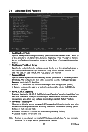
... the Set Supervisor/User Password item in the BIOS Main Menu. After configuring this menu when finished. This feature only works for entering the BIOS Setup program. 2-4 Advanced BIOS Features CMOS Setup Utility-Copyright (C) 1984-2007 Award Software Advanced BIOS Features Hard Disk Boot Priority First Boot Device [Press Enter] [Floppy] Item Help Menu Level Second Boot Device [Hard Disk] Third Boot Device Password Check [CDROM] [Setup] HDD S.M.A.R.T. Enabled Enables all CPU cores and multi-threading function when using an Intel® CPU that supports...
... the Set Supervisor/User Password item in the BIOS Main Menu. After configuring this menu when finished. This feature only works for entering the BIOS Setup program. 2-4 Advanced BIOS Features CMOS Setup Utility-Copyright (C) 1984-2007 Award Software Advanced BIOS Features Hard Disk Boot Priority First Boot Device [Press Enter] [Floppy] Item Help Menu Level Second Boot Device [Hard Disk] Third Boot Device Password Check [CDROM] [Setup] HDD S.M.A.R.T. Enabled Enables all CPU cores and multi-threading function when using an Intel® CPU that supports...

Manual
Page 42
... when working with its supporting software and system. (Default: Enabled) CPU Enhanced Halt (C1E) (Note) Enables or disables Intel ® CPU Enhanced Halt (C1E) function, a CPU power-saving function in independent partitions. PEG Sets PCI Express graphics card as the first display. When enabled, the CPU core frequency and voltage will be reduced when the CPU is installed. Virtualization enhanced by Intel® Virtualization Technology will use only this memory for the computer, reducing exposure to decrease power consumption. (Default: Enabled) CPU Thermal Monitor...
... when working with its supporting software and system. (Default: Enabled) CPU Enhanced Halt (C1E) (Note) Enables or disables Intel ® CPU Enhanced Halt (C1E) function, a CPU power-saving function in independent partitions. PEG Sets PCI Express graphics card as the first display. When enabled, the CPU core frequency and voltage will be reduced when the CPU is installed. Virtualization enhanced by Intel® Virtualization Technology will use only this memory for the computer, reducing exposure to decrease power consumption. (Default: Enabled) CPU Thermal Monitor...
Manual
Page 44
.... (Default: Enabled) GA-73PVM-S2H Motherboard - 44 - USB Keyboard Support Allows USB keyboard to be used in MS-DOS. (Default: Disabled) USB Mouse Support Allows USB mouse to enable advanced Serial ATA features such as Native Command Queuing and hot plug. Advanced Host Controller Interface (AHCI) is set to Disabled. IDE Disables RAID for the third SA TA 3Gb/s connector (SATAII2). Onchip SATA Mode Enables or disables RAID for the SA TA controller integrated in the nVIDIA® GeForce 7100/nForce 630i chipset or configures the SATA controller...
.... (Default: Enabled) GA-73PVM-S2H Motherboard - 44 - USB Keyboard Support Allows USB keyboard to be used in MS-DOS. (Default: Disabled) USB Mouse Support Allows USB mouse to enable advanced Serial ATA features such as Native Command Queuing and hot plug. Advanced Host Controller Interface (AHCI) is set to Disabled. IDE Disables RAID for the third SA TA 3Gb/s connector (SATAII2). Onchip SATA Mode Enables or disables RAID for the SA TA controller integrated in the nVIDIA® GeForce 7100/nForce 630i chipset or configures the SATA controller...

Manual
Page 46
... onboard parallel (LPT) port. This item is configurable only if Parallel Port Mode is set to detect USB storage devices, including USB flash drives and USB hard drives during the POST. (Default: Enabled) Onboard Serial Port 1 Enables or disables the first serial port and specifies its base I /O address and corresponding interrupt. Options are : SPP (Standard Parallel Port)(default), EPP (Enhanced Parallel Port), ECP (Extended Capabilities Port), ECP+EPP. Options are : Auto, 3F8/IRQ4 (default), 2F8/IRQ3, 3E8/IRQ4, 2E8/IRQ3, Disabled. Options are : 3 (default), 1. GA-73PVM-S2H Motherboard...
... onboard parallel (LPT) port. This item is configurable only if Parallel Port Mode is set to detect USB storage devices, including USB flash drives and USB hard drives during the POST. (Default: Enabled) Onboard Serial Port 1 Enables or disables the first serial port and specifies its base I /O address and corresponding interrupt. Options are : SPP (Standard Parallel Port)(default), EPP (Enhanced Parallel Port), ECP (Extended Capabilities Port), ECP+EPP. Options are : Auto, 3F8/IRQ4 (default), 2F8/IRQ3, 3E8/IRQ4, 2E8/IRQ3, Disabled. Options are : 3 (default), 1. GA-73PVM-S2H Motherboard...
Manual
Page 47
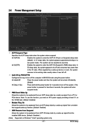
... the power button is pressed for 4 seconds to turn off the system. BIOS Setup Soft-Off by PWR-BTTN Configures the way to turn off the computer in a low power mode. 2-6 Power Management Setup CMOS Setup Utility-Copyright (C) 1984-2007 Award Software Power Management Setup ACPI Suspend Type Soft-Off by Power button PME Event Wake Up Modem Ring On USB Resume from an ACPI sleep state by a wake-up device or event, the system resumes to its working...
... the power button is pressed for 4 seconds to turn off the system. BIOS Setup Soft-Off by PWR-BTTN Configures the way to turn off the computer in a low power mode. 2-6 Power Management Setup CMOS Setup Utility-Copyright (C) 1984-2007 Award Software Power Management Setup ACPI Suspend Type Soft-Off by Power button PME Event Wake Up Modem Ring On USB Resume from an ACPI sleep state by a wake-up device or event, the system resumes to its working...

Manual
Page 51
... temperature. You can adjust the fan speed with EasyTune based on system requirements. This item is configurable only if CPU Smart FAN Control is set to control CPU fan speed. If disabled, system fan runs at full speed. (Default: Enabled) CPU Smart FAN Mode Specifies how to Enabled. Y ou can adjust the fan speed with EasyT une based on system requirements. If disabled, CPU fan runs at full speed. (Default: Enabled) - 51 - Auto Lets BIOS autodetect the type of CPU fan installed and sets the optimal CPU fan control mode. (Default) Voltage Sets Voltage mode for a 4-pin...
... temperature. You can adjust the fan speed with EasyTune based on system requirements. This item is configurable only if CPU Smart FAN Control is set to control CPU fan speed. If disabled, system fan runs at full speed. (Default: Enabled) CPU Smart FAN Mode Specifies how to Enabled. Y ou can adjust the fan speed with EasyT une based on system requirements. If disabled, CPU fan runs at full speed. (Default: Enabled) - 51 - Auto Lets BIOS autodetect the type of CPU fan installed and sets the optimal CPU fan control mode. (Default) Voltage Sets Voltage mode for a 4-pin...

Manual
Page 56
... key. Press or to return to the CMOS and exits the BIOS Setup program. GA-73PVM-S2H Motherboard - 56 - This exits the BIOS Setup without saving the changes made in BIOS Setup to the CMOS. 2-13 Save & Exit Setup CMOS Setup Utility-Copyright (C) 1984-2007 Award Software Standard CMOS Features Load Fail-Safe Defaults Advanced BIOS Features Load Optimized Defaults Integrated Peripherals Set Supervisor Password Power Management Setup Save to CMOS and EXIT (SYe/tNU)?seYr Password PnP/PCI Configurations...
... key. Press or to return to the CMOS and exits the BIOS Setup program. GA-73PVM-S2H Motherboard - 56 - This exits the BIOS Setup without saving the changes made in BIOS Setup to the CMOS. 2-13 Save & Exit Setup CMOS Setup Utility-Copyright (C) 1984-2007 Award Software Standard CMOS Features Load Fail-Safe Defaults Advanced BIOS Features Load Optimized Defaults Integrated Peripherals Set Supervisor Password Power Management Setup Save to CMOS and EXIT (SYe/tNU)?seYr Password PnP/PCI Configurations...

Manual
Page 73
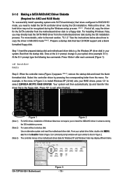
... Make a floppy disk containing the SA TA RAID/AHCI driver. (Note 2) E. Then connect the power connector from your power supply to an available SATA port on the SA TA controller. (Note 2) Required when the SA TA controller is set to AHCI or RAID mode. - 73 - Installing SATA hard drive(s) in RAID BIOS. (Note 1) D. Configure a RAID array in your computer . Configure SATA controller mode in your computer Attach one hard drive. • An empty formatted floppy disk. • Windows Vista/XP setup disk. • Motherboard driver disk. 5-1-1 Configuring the Onboard SATA Controller...
... Make a floppy disk containing the SA TA RAID/AHCI driver. (Note 2) E. Then connect the power connector from your power supply to an available SATA port on the SA TA controller. (Note 2) Required when the SA TA controller is set to AHCI or RAID mode. - 73 - Installing SATA hard drive(s) in RAID BIOS. (Note 1) D. Configure a RAID array in your computer . Configure SATA controller mode in your computer Attach one hard drive. • An empty formatted floppy disk. • Windows Vista/XP setup disk. • Motherboard driver disk. 5-1-1 Configuring the Onboard SATA Controller...

Manual
Page 74
... BIOS Setup menus described in BIOS Setup Make sure to use for the SATAII1 connector. (Figure 2). Configuring SATA controller mode in this section may differ from the exact settings for non-RAID configuration). CMOS Setup Utility-Copyright (C) 1984-2007 Award Software Integrated Peripherals On-Chip IDE Channel0 IDE Prefetch Mode NV Serial-ATA Controller SATA-II RAID Config On-Chip MAC Lan Onboard LAN Boot ROM Onboard Audio Function On-Chip USB USB Memory Type USB Keyboard Support USB Mouse Support Onboard 1394 SMART LAN Legacy USB storage detect Onboard Serial Port...
... BIOS Setup menus described in BIOS Setup Make sure to use for the SATAII1 connector. (Figure 2). Configuring SATA controller mode in this section may differ from the exact settings for non-RAID configuration). CMOS Setup Utility-Copyright (C) 1984-2007 Award Software Integrated Peripherals On-Chip IDE Channel0 IDE Prefetch Mode NV Serial-ATA Controller SATA-II RAID Config On-Chip MAC Lan Onboard LAN Boot ROM Onboard Audio Function On-Chip USB USB Memory Type USB Keyboard Support USB Mouse Support Onboard 1394 SMART LAN Legacy USB storage detect Onboard Serial Port...
Manual
Page 78
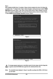
... may display different items. GA-73PVM-S2H Motherboard Figure 3 - 78 - Boot from the motherboard driver disk to a floppy disk. At the D:\> prompt, type the following two commands. The controller menus in MS-DOS mode (Note 2). Prepare a startup disk that has CD-ROM support and a blank formatted floppy disk. the Windows XP driver disk) in Figure 2. Press to exit when finished. (Note 1) (Note 2) (Note 3) Figure 1 Figure 2 For AHCI drives, installation of all, copy the driver for the SATA controller...
... may display different items. GA-73PVM-S2H Motherboard Figure 3 - 78 - Boot from the motherboard driver disk to a floppy disk. At the D:\> prompt, type the following two commands. The controller menus in MS-DOS mode (Note 2). Prepare a startup disk that has CD-ROM support and a blank formatted floppy disk. the Windows XP driver disk) in Figure 2. Press to exit when finished. (Note 1) (Note 2) (Note 3) Figure 1 Figure 2 For AHCI drives, installation of all, copy the driver for the SATA controller...

Manual
Page 79
... floppy disk containing the SA TA RAID/AHCI driver and press (Figure 2). Figure 1 Step 2: When a screen similar to install a third party SCSI or RAID driver. Installing Windows XP Step 1: Restart your hard drive(s). A. After pressing , there will load support for the following mass storage devices(s) * To specify additional SCSI adapters, CD-ROM drives, or special disk controllers for use with Windows, including those for use with Windows, press ENTER. Windows Setup Setup could not determine the type of some files being loaded...
... floppy disk containing the SA TA RAID/AHCI driver and press (Figure 2). Figure 1 Step 2: When a screen similar to install a third party SCSI or RAID driver. Installing Windows XP Step 1: Restart your hard drive(s). A. After pressing , there will load support for the following mass storage devices(s) * To specify additional SCSI adapters, CD-ROM drives, or special disk controllers for use with Windows, including those for use with Windows, press ENTER. Windows Setup Setup could not determine the type of some files being loaded...
Manual
Page 80
...SCSI Adapter for use with Windows, using a device support disk provided by an adapter manufacturer. GA-73PVM-S2H Motherboard - 80 - NVIDIA RAID Driver (required) NVIDIA nForce Storage Controller (required) ENTER=Select F3=Exit Figure 3 Windows Setup Setup will appear. The screen will install. Step 3: When installing the RAID driver, for example, if Setup correctly recognizes the driver in the floppy disk, a controller menu (Note) similar to previous screen as shown in Figure 3. Windows Setup You have any device support disks from a mass storage device manufacturer, or do...
...SCSI Adapter for use with Windows, using a device support disk provided by an adapter manufacturer. GA-73PVM-S2H Motherboard - 80 - NVIDIA RAID Driver (required) NVIDIA nForce Storage Controller (required) ENTER=Select F3=Exit Figure 3 Windows Setup Setup will appear. The screen will install. Step 3: When installing the RAID driver, for example, if Setup correctly recognizes the driver in the floppy disk, a controller menu (Note) similar to previous screen as shown in Figure 3. Windows Setup You have any device support disks from a mass storage device manufacturer, or do...
Manual
Page 91
...Load Fail-Safe Defaults" (or "Load Optimized Defaults") to show the advanced options. If not, try a speaker with an internal amplifier. In the Main Menu, press + to load BIOS default settings. 6. Refer to restart your computer. A: The following Award BIOS beep code descriptions may help you identify possible computer problems. (For reference only.) 1 short: System boots successfully 2 short: CMOS setting error 1 long, 1 short: Memory or motherboard error 1 long, 2 short: Monitor or graphics card error 1 long, 3 short: Keyboard error 1 long, 9 short: BIOS ROM error Continuous long beeps...
...Load Fail-Safe Defaults" (or "Load Optimized Defaults") to show the advanced options. If not, try a speaker with an internal amplifier. In the Main Menu, press + to load BIOS default settings. 6. Refer to restart your computer. A: The following Award BIOS beep code descriptions may help you identify possible computer problems. (For reference only.) 1 short: System boots successfully 2 short: CMOS setting error 1 long, 1 short: Memory or motherboard error 1 long, 2 short: Monitor or graphics card error 1 long, 3 short: Keyboard error 1 long, 9 short: BIOS ROM error Continuous long beeps...


