Manual
Page 2
...to Installation 5 1-2 Feature Summary 6 1-3 Installation of Memory 8 1-4 Installation of Expansion Cards 9 1-5 I/O Back Panel Introduction 10 1-6 Connectors Introduction 11 Chapter 2 BIOS Setup 19 The Main Menu (For example: BIOS Ver. :F4 20 2-1 Standard CMOS Features 22 2-2 Advanced BIOS Features 24 2-3 Advanced Chipset Features 27 2-3 IntegratedPeripherals 33 2-4 Power Management Setup 37 2-5 PnP/PCI Configurations 41 2-6 PC Health Status 42 2-7 Frequency / Voltage Control 43 2-8 Load Fail-Safe Defaults 44 2-9 Load Optimized Defaults 44 2-10 Set Supervisor/User Password 45...
...to Installation 5 1-2 Feature Summary 6 1-3 Installation of Memory 8 1-4 Installation of Expansion Cards 9 1-5 I/O Back Panel Introduction 10 1-6 Connectors Introduction 11 Chapter 2 BIOS Setup 19 The Main Menu (For example: BIOS Ver. :F4 20 2-1 Standard CMOS Features 22 2-2 Advanced BIOS Features 24 2-3 Advanced Chipset Features 27 2-3 IntegratedPeripherals 33 2-4 Power Management Setup 37 2-5 PnP/PCI Configurations 41 2-6 PC Health Status 42 2-7 Frequency / Voltage Control 43 2-8 Load Fail-Safe Defaults 44 2-9 Load Optimized Defaults 44 2-10 Set Supervisor/User Password 45...
Manual
Page 6
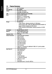
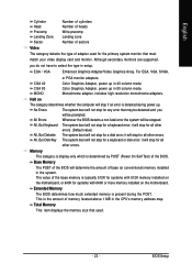
... of 2 SATA devices O.S Support Š Microsoft Windows 2000/XP Memory Š 1 DDRII DIMM memory slots Š Supports 1.8V DDRII DIMMs Expanstion Slots Š 1 PCI slots Internal Connectors Š 1 20-pin ATX power connector Š 2 IDE connectors Š 2 SATA connectors Š 1 CPU fan connector Š 1 system fan connector Š 1 front panel connector Š 1 front audio connector Š 1 CD In connector Š 2 USB 2.0/1.1 connectors for additional 4 USB 2.0/1.1 ports by cables Š 1 SPDIF In/Out connector Rear Panel I/O Š 1 PS/2 keyboard port Š...
... of 2 SATA devices O.S Support Š Microsoft Windows 2000/XP Memory Š 1 DDRII DIMM memory slots Š Supports 1.8V DDRII DIMMs Expanstion Slots Š 1 PCI slots Internal Connectors Š 1 20-pin ATX power connector Š 2 IDE connectors Š 2 SATA connectors Š 1 CPU fan connector Š 1 system fan connector Š 1 front panel connector Š 1 front audio connector Š 1 CD In connector Š 2 USB 2.0/1.1 connectors for additional 4 USB 2.0/1.1 ports by cables Š 1 SPDIF In/Out connector Rear Panel I/O Š 1 PS/2 keyboard port Š...
Manual
Page 13
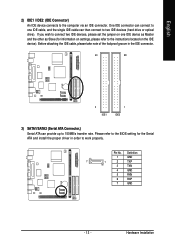
... to two IDE devices (hard drive or optical drive). One IDE connector can connect to one IDE device as Master and the other as Slave (for the Serial ATA and install the proper driver in the IDE connector. 40 39 2 IDE1 1 IDE2 3) SATA1/SATA2 (Serial ATA Connector,) Serial ATA can then connect to work properly. Pin No. English 2) IDE1 / IDE2 (IDE Connector) An IDE device connects to the instructions located on the IDE device). Please refer to the BIOS setting for information...
... to two IDE devices (hard drive or optical drive). One IDE connector can connect to one IDE device as Master and the other as Slave (for the Serial ATA and install the proper driver in the IDE connector. 40 39 2 IDE1 1 IDE2 3) SATA1/SATA2 (Serial ATA Connector,) Serial ATA can then connect to work properly. Pin No. English 2) IDE1 / IDE2 (IDE Connector) An IDE device connects to the instructions located on the IDE device). Please refer to the BIOS setting for information...
Manual
Page 14
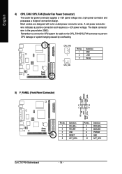
.... GA-C7V7-RH Motherboard - 14 - PWRSW GND ACT_LED- 2 10 1 9 HD+ HDRESET GND ACT_LED+ Pin No. 1 3 5 7 9 Definition HD_LED+ HD_LEDGND RESET ACT_LED+ Pin No. 2 4 6 8 10 Definition MSGLED+ MSGLEDPWRSW GND ACT_LED- CPU_FAN 1 1 SYS_FAN Pin No. 1 2 3 Definition GND +12V Sense 5) F_PANEL (Front Panel Connector) MSG+ MSG- English 4) CPU_FAN / SYS_FAN (Cooler Fan Power Connector) The cooler fan power connector supplies a +12V power voltage via a 3-pin power connector and possesses a foolproof connection design. A red power connector wire indicates a positive connection and...
.... GA-C7V7-RH Motherboard - 14 - PWRSW GND ACT_LED- 2 10 1 9 HD+ HDRESET GND ACT_LED+ Pin No. 1 3 5 7 9 Definition HD_LED+ HD_LEDGND RESET ACT_LED+ Pin No. 2 4 6 8 10 Definition MSGLED+ MSGLEDPWRSW GND ACT_LED- CPU_FAN 1 1 SYS_FAN Pin No. 1 2 3 Definition GND +12V Sense 5) F_PANEL (Front Panel Connector) MSG+ MSG- English 4) CPU_FAN / SYS_FAN (Cooler Fan Power Connector) The cooler fan power connector supplies a +12V power voltage via a 3-pin power connector and possesses a foolproof connection design. A red power connector wire indicates a positive connection and...
Manual
Page 19
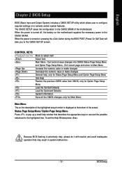
... the Help Window press . English Chapter 2 BIOS Setup BIOS (Basic Input and Output System) includes a CMOS SETUP utility which allows user to configure required settings or to the CMOS SETUP screen. CONTROL KEYS Enter> Move to the CMOS SRAM. The CMOS SETUP saves the configuration in system malfunction. - 19 - When the power is turned on the motherboard supplies the necessary power to select item Select Item Main Menu - Quit and not save changes into CMOS Status Page Setup Menu and Option Page Setup Menu -
... the Help Window press . English Chapter 2 BIOS Setup BIOS (Basic Input and Output System) includes a CMOS SETUP utility which allows user to configure required settings or to the CMOS SETUP screen. CONTROL KEYS Enter> Move to the CMOS SRAM. The CMOS SETUP saves the configuration in system malfunction. - 19 - When the power is turned on the motherboard supplies the necessary power to select item Select Item Main Menu - Quit and not save changes into CMOS Status Page Setup Menu and Option Page Setup Menu -
Manual
Page 20
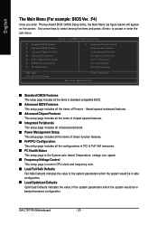
... CMOS Setup Utility Standard CMOS Features Advanced BIOS Features Advanced Chipset Features Integrated Peripherals Power Management Setup PnP/PCI Configurations PC Health Status Frequency/Voltage Control Load Fail-Safe Defaults Load Optimized Defaults Set Supervisor Password Set User Password Save & Exit Setup Exit Without Saving ESC: Quit F10: Save & Exit Setup : Select Item Time, Date, Hard Disk Type... „ Standard CMOS Features This setup page includes all the items in standard compatible BIOS. „ Advanced BIOS Features This setup page includes all the configurations of PCI...
... CMOS Setup Utility Standard CMOS Features Advanced BIOS Features Advanced Chipset Features Integrated Peripherals Power Management Setup PnP/PCI Configurations PC Health Status Frequency/Voltage Control Load Fail-Safe Defaults Load Optimized Defaults Set Supervisor Password Set User Password Save & Exit Setup Exit Without Saving ESC: Quit F10: Save & Exit Setup : Select Item Time, Date, Hard Disk Type... „ Standard CMOS Features This setup page includes all the items in standard compatible BIOS. „ Advanced BIOS Features This setup page includes all the configurations of PCI...
Manual
Page 22
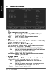
... device detection. The four options are: CHS/LBA/Large/Auto(default:Auto) IDE Channel 2/3 Master IDE HDD Auto-Detection Press "Enter" to select this option for faster system start up . GA-C7V7-RH Motherboard - 22 - AwardBIOS CMOS Setup Utility Standard CMOS Features Tue, Mar 15 2006 14:42:37 [None] [None] [None] [None] [None] [None] Video Halt On Base Memory Extended Memory Total Memory [EGA/VGA] [All, But Keyboard] 640K 511M 512M Item Help Menu Level Change...
... device detection. The four options are: CHS/LBA/Large/Auto(default:Auto) IDE Channel 2/3 Master IDE HDD Auto-Detection Press "Enter" to select this option for faster system start up . GA-C7V7-RH Motherboard - 22 - AwardBIOS CMOS Setup Utility Standard CMOS Features Tue, Mar 15 2006 14:42:37 [None] [None] [None] [None] [None] [None] Video Halt On Base Memory Extended Memory Total Memory [EGA/VGA] [All, But Keyboard] 640K 511M 512M Item Help Menu Level Change...
Manual
Page 23
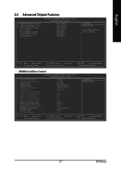
... disk error; Total Memory This item displays the memory size that must match your video display card and monitor. EGA / VGA Enhanced Graphics Adapter/Video Graphics Array. Color Graphics Adapter, power up . Monochrome adapter, includes high resolution monochrome adapters. All, But Disk/Key The system boot will be stopped. Memory The category is display-only which is detected during the POST. Halt on the motherboard. Although secondary monitors are supported, you will not stop for a keyboard error; Extended Memory...
... disk error; Total Memory This item displays the memory size that must match your video display card and monitor. EGA / VGA Enhanced Graphics Adapter/Video Graphics Array. Color Graphics Adapter, power up . Monochrome adapter, includes high resolution monochrome adapters. All, But Disk/Key The system boot will be stopped. Memory The category is display-only which is detected during the POST. Halt on the motherboard. Although secondary monitors are supported, you will not stop for a keyboard error; Extended Memory...
Manual
Page 24
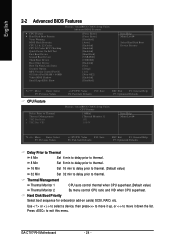
... Thermal Management Thermal Monitor 1 Thermal Monitor 2 CPU auto control thermal when CPU superheat.(Default value) By menu control CPU ratio and VID when CPU superheat. Hard Disk Boot Priority Select boot sequence for onboard(or add-on cards) SCSI, RAID, etc. AwardBIOS CMOS Setup Utility Advanced BIOS Features [Press Enter] [Press Enter] [Disabled] [Auto] [Enabled] [Enabled] [Enabled] [Hard Disk] [USB-FDD] [CDROM] [Enabled] [On] [Setup] [1.4] [Non-OS2] [Enabled] [Disabled] Item Help Menu Level Select Hard Disk Boot Device Priority : Move Enter: Select F5: Previous Values CPU Feature Delay...
... Thermal Management Thermal Monitor 1 Thermal Monitor 2 CPU auto control thermal when CPU superheat.(Default value) By menu control CPU ratio and VID when CPU superheat. Hard Disk Boot Priority Select boot sequence for onboard(or add-on cards) SCSI, RAID, etc. AwardBIOS CMOS Setup Utility Advanced BIOS Features [Press Enter] [Press Enter] [Disabled] [Auto] [Enabled] [Enabled] [Enabled] [Hard Disk] [USB-FDD] [CDROM] [Enabled] [On] [Setup] [1.4] [Non-OS2] [Enabled] [Disabled] Item Help Menu Level Select Hard Disk Boot Device Priority : Move Enter: Select F5: Previous Values CPU Feature Delay...
Manual
Page 25
... the screen when there is set to access the boot sector or hard disk partition table. USB-HDD Select your boot device priority by Legacy LAN. USB-FDD Select your boot device priority by CDROM. ZIP100 Select your boot device priority by USB-HDD. Auto BIOS enables flash write access automatically when updating BIOS data/DMI/ESCD. (Default Value) Enabled During POST, DMI/ESCD would not be updated. The system will halt and the warning message will flash on CPU / chipset design. Disabled No...
... the screen when there is set to access the boot sector or hard disk partition table. USB-HDD Select your boot device priority by Legacy LAN. USB-FDD Select your boot device priority by CDROM. ZIP100 Select your boot device priority by USB-HDD. Auto BIOS enables flash write access automatically when updating BIOS data/DMI/ESCD. (Default Value) Enabled During POST, DMI/ESCD would not be updated. The system will halt and the warning message will flash on CPU / chipset design. Disabled No...
Manual
Page 27
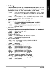
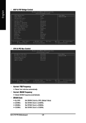
...: Value F10: Save F6: Fail-Safe Defaults ESC: Exit F1: General Help F7: Optimized Defaults - 27 - BIOS Setup AwardBIOS CMOS Setup Utility Advanced Chipset Features [Press Enter] [Press Enter] [Press Enter] [Disabled] [Enabled] [Disabled] [PCI Slot] Item Help Menu Level Select Hard Disk Boot Device Priority : Move Enter: Select F5: Previous Values +/-/PU/PD: Value F10: Save F6: Fail-Safe Defaults ESC: Exit F1: General Help F7: Optimized Defaults DRAM Clock/Drive Control Current FSB Frequency Current DRAM Frequency DRAM Clock DRAM Timing x SDRAM CAS Latency...
...: Value F10: Save F6: Fail-Safe Defaults ESC: Exit F1: General Help F7: Optimized Defaults - 27 - BIOS Setup AwardBIOS CMOS Setup Utility Advanced Chipset Features [Press Enter] [Press Enter] [Press Enter] [Disabled] [Enabled] [Disabled] [PCI Slot] Item Help Menu Level Select Hard Disk Boot Device Priority : Move Enter: Select F5: Previous Values +/-/PU/PD: Value F10: Save F6: Fail-Safe Defaults ESC: Exit F1: General Help F7: Optimized Defaults DRAM Clock/Drive Control Current FSB Frequency Current DRAM Frequency DRAM Clock DRAM Timing x SDRAM CAS Latency...
Manual
Page 28
...Display Device Panel Type Outport Port Dithering TV-Layout TV-type TV-connector [128M] [8X] [Auto] DA [Disabled] [Enabled] [Enabled] [Disabled] [64M] [Enabled] [CRT] [07] [DI0] [Disabled] [Default] [NTSC] [CVBS] Item Help Menu Level : Move Enter: Select F5: Previous Values +/-/PU/PD: Value F10: Save F6: Fail-Safe Defaults ESC: Exit F1: General Help F7: Optimized Defaults CPU & PCI Bus Control PCI Master 0 WS Write PCI Delay Transaction VLink mode selection VLink 8x Support DRDY_Timing Phoenix- AwardBIOS CMOS Setup Utility CPU & PCI Bus Control [Enabled] [Enabled] [By Auto] [Enabled...
...Display Device Panel Type Outport Port Dithering TV-Layout TV-type TV-connector [128M] [8X] [Auto] DA [Disabled] [Enabled] [Enabled] [Disabled] [64M] [Enabled] [CRT] [07] [DI0] [Disabled] [Default] [NTSC] [CVBS] Item Help Menu Level : Move Enter: Select F5: Previous Values +/-/PU/PD: Value F10: Save F6: Fail-Safe Defaults ESC: Exit F1: General Help F7: Optimized Defaults CPU & PCI Bus Control PCI Master 0 WS Write PCI Delay Transaction VLink mode selection VLink 8x Support DRDY_Timing Phoenix- AwardBIOS CMOS Setup Utility CPU & PCI Bus Control [Enabled] [Enabled] [By Auto] [Enabled...
Manual
Page 29
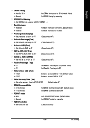
... is 3T. RDSAIT mode Auto Auto detect RDSAIT mode. (Default value) Manual Set RDSAIT mode by manually. Write Recovery Time (Twr) Set write recovery time to 2T/3T/4T/5T (Default value:4T) DRAM Command Rate 2T Command Set DRAM Command rate to 2T. (Default value) 1T Command Set DRAM Command rate to 03 (Default value:03) - 29 - BIOS Setup Precharge to Active (Trp) Set precharge to active to 4T (Default value:4T) Active...
... is 3T. RDSAIT mode Auto Auto detect RDSAIT mode. (Default value) Manual Set RDSAIT mode by manually. Write Recovery Time (Twr) Set write recovery time to 2T/3T/4T/5T (Default value:4T) DRAM Command Rate 2T Command Set DRAM Command rate to 2T. (Default value) 1T Command Set DRAM Command rate to 03 (Default value:03) - 29 - BIOS Setup Precharge to Active (Trp) Set precharge to active to 4T (Default value:4T) Active...
Manual
Page 30
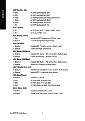
... (Default value) Enabled Enabled AGP Master 1 WS write function. AGP Driving control Auto Auto detect AGP driving control. (Default value) Manual Set AGP driving control by manually. AGP 3.0 Calibration cycle Disabled Disabled AGP 3.0 calibration cycle function. (Default value) Enabled Enabled AGP 3.0 calibration cycle function. AGP 3.0 Mode 8X Set 8x to AGP AGP 3.0 mode. (Default value) 4X Set 4x to 64M.(Default value) Direct Frame Buffer Disabled Disabled direct fram buffer function. Enabled Enabled direct fram buffer function. (Default value) GA-C7V7-RH Motherboard...
... (Default value) Enabled Enabled AGP Master 1 WS write function. AGP Driving control Auto Auto detect AGP driving control. (Default value) Manual Set AGP driving control by manually. AGP 3.0 Calibration cycle Disabled Disabled AGP 3.0 calibration cycle function. (Default value) Enabled Enabled AGP 3.0 calibration cycle function. AGP 3.0 Mode 8X Set 8x to AGP AGP 3.0 mode. (Default value) 4X Set 4x to 64M.(Default value) Direct Frame Buffer Disabled Disabled direct fram buffer function. Enabled Enabled direct fram buffer function. (Default value) GA-C7V7-RH Motherboard...
Manual
Page 31
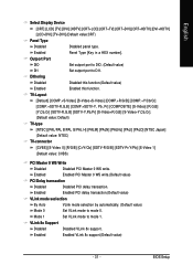
...-Pr/Y/Pb] [S-Video 1] (Default value: CVBS) PCI Master 0 WS Write Disabled Disabled PCI Master 0 WS write. Enabled Enabled PCI delay transaction.(Default value) VLink mode seclection By Auto VLink mode selection by automatically. (Default value) Mode 0 Set VLink mode to DI1. BIOS Setup Dithering Disabled Disabled this function.(Default value) Enabled Enabled this function. Enabled Enabled VLink 8x support.(Default value) - 31 - VLink 8x Support Disabled Disabled VLink 8x support. Mode 1 Set VLink mode to mode 1. Enabled Panel Type [Key in a HEX number...
...-Pr/Y/Pb] [S-Video 1] (Default value: CVBS) PCI Master 0 WS Write Disabled Disabled PCI Master 0 WS write. Enabled Enabled PCI delay transaction.(Default value) VLink mode seclection By Auto VLink mode selection by automatically. (Default value) Mode 0 Set VLink mode to DI1. BIOS Setup Dithering Disabled Disabled this function.(Default value) Enabled Enabled this function. Enabled Enabled VLink 8x support.(Default value) - 31 - VLink 8x Support Disabled Disabled VLink 8x support. Mode 1 Set VLink mode to mode 1. Enabled Panel Type [Key in a HEX number...
Manual
Page 35
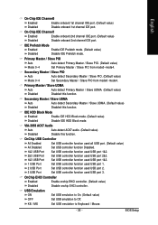
... all USB port. (Default value) All Disabled Set USB controller function Disabled. 1&2 USB Port 2&3 USB Port Set USB controller function used USB port 3. BIOS Setup Set USB controller function used USB port 1. 2 USB Port Set USB controller function used USB port 2. 3 USB Port Set USB controller function used USB port 1&2. English On-Chip IDE Channel0 Enabled Enable onboard 1st channel IDE port. (Default value) Disabled Disable onboard 1st channel IDE port. Secondary Master / Slave PIO Auto Auto detect Secondary Master / Slave PIO. (Default value) Mode 0~4 Set...
... all USB port. (Default value) All Disabled Set USB controller function Disabled. 1&2 USB Port 2&3 USB Port Set USB controller function used USB port 3. BIOS Setup Set USB controller function used USB port 1. 2 USB Port Set USB controller function used USB port 2. 3 USB Port Set USB controller function used USB port 1&2. English On-Chip IDE Channel0 Enabled Enable onboard 1st channel IDE port. (Default value) Disabled Disable onboard 1st channel IDE port. Secondary Master / Slave PIO Auto Auto detect Secondary Master / Slave PIO. (Default value) Mode 0~4 Set...
Manual
Page 36
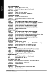
...USB keyboard support.(Default value) USB Mouse Support Disabled Disable USB mouse support. Onboard Serial Port 2 Auto BIOS will automatically setup the Serial port 1 address. Enable onboard LPT port and address is 3F8/IRQ4. ECP Mode Use DMA 3 Set ECP Mode Use DMA to 3. (Default value) 1 Set ECP Mode Use DMA to invoke the boot ROM of the onboard LAN chip. Onboard Parallel Port Disabled Disable onboard LPT port. 378/IRQ7 Enable onboard LPT port and address is 378/IRQ7. (Default value) 278/IRQ5 3BC/IRQ7 Enable onboard LPT port and address is 2E8/IRQ3. On-Chip LAN...
...USB keyboard support.(Default value) USB Mouse Support Disabled Disable USB mouse support. Onboard Serial Port 2 Auto BIOS will automatically setup the Serial port 1 address. Enable onboard LPT port and address is 3F8/IRQ4. ECP Mode Use DMA 3 Set ECP Mode Use DMA to 3. (Default value) 1 Set ECP Mode Use DMA to invoke the boot ROM of the onboard LAN chip. Onboard Parallel Port Disabled Disable onboard LPT port. 378/IRQ7 Enable onboard LPT port and address is 378/IRQ7. (Default value) 278/IRQ5 3BC/IRQ7 Enable onboard LPT port and address is 2E8/IRQ3. On-Chip LAN...
Manual
Page 38
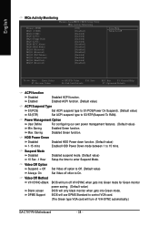
....) GA-C7V7-RH Motherboard - 38 - DPMS Support BIOS will use DPMS Standard to control VGA card. (The Green type VGA card will only black monitor when gets into Green mode for Green monitor Blank screen power saving. (Default value) BIOS will turn off oftion to 15 mins. HDD Power Down Disabled Disabled HDD Power down function. (Default value) 1-15 mins Enabled HDD Power Down mode between 1 to On. English IRQs Activity Monitoring Phoenix- Power Management Option User Define For configuring our own power management features. (Default value...
....) GA-C7V7-RH Motherboard - 38 - DPMS Support BIOS will use DPMS Standard to control VGA card. (The Green type VGA card will only black monitor when gets into Green mode for Green monitor Blank screen power saving. (Default value) BIOS will turn off oftion to 15 mins. HDD Power Down Disabled Disabled HDD Power down function. (Default value) 1-15 mins Enabled HDD Power Down mode between 1 to On. English IRQs Activity Monitoring Phoenix- Power Management Option User Define For configuring our own power management features. (Default value...
Manual
Page 41
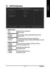
...-Safe Defaults ESC: Exit F1: General Help F7: Optimized Defaults PNP OS Installed No Disabled this function. (Default value) Yes Enabled this function. BIOS Setup English 2-5 PnP/PCI Configurations PNP OS Installed Reset Configuration Data Resources Controlled By x IRQ Resources PCI/VGA Palette Snoop Assign IRQ For VGA Assign IRQ For USB Phoenix- Resources Controlled By Auto(ESCD) BIOS automatically use these PnP rescuers. (Default value) Manual User can set the PnP resource (I/O Address, IRQ & DMAchannels) used by legacy...
...-Safe Defaults ESC: Exit F1: General Help F7: Optimized Defaults PNP OS Installed No Disabled this function. (Default value) Yes Enabled this function. BIOS Setup English 2-5 PnP/PCI Configurations PNP OS Installed Reset Configuration Data Resources Controlled By x IRQ Resources PCI/VGA Palette Snoop Assign IRQ For VGA Assign IRQ For USB Phoenix- Resources Controlled By Auto(ESCD) BIOS automatically use these PnP rescuers. (Default value) Manual User can set the PnP resource (I/O Address, IRQ & DMAchannels) used by legacy...
Manual
Page 45
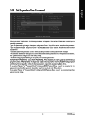
... press . English 2-10 Set Supervisor/User Password Phoenix- AwardBIOS CMOS Setup Utility Standard CMOS Features Advanced BIOS Features Advanced Chipset Features Integrated PeripherEalnster Password: Power Management Setup PnP/PCI Configurations PC Health Status Frequency/Voltage Control Load Fail-Safe Defaults Load Optimized Defaults Set Supervisor Password Set User Password Save & Exit Setup Exit Without Saving ESC: Quit F10: Save & Exit Setup : Select Item Change/Set/Disable Password When you will appear at "Password Check" in creating a password. Type the password, up to confirm...
... press . English 2-10 Set Supervisor/User Password Phoenix- AwardBIOS CMOS Setup Utility Standard CMOS Features Advanced BIOS Features Advanced Chipset Features Integrated PeripherEalnster Password: Power Management Setup PnP/PCI Configurations PC Health Status Frequency/Voltage Control Load Fail-Safe Defaults Load Optimized Defaults Set Supervisor Password Set User Password Save & Exit Setup Exit Without Saving ESC: Quit F10: Save & Exit Setup : Select Item Change/Set/Disable Password When you will appear at "Password Check" in creating a password. Type the password, up to confirm...


