
Quick Reference Guide
Page 1
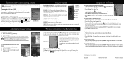
...From the Home screen, select Information > User Data > Waypoints. 2. From any screen, press MARK. 2. Select Create Waypoint. Select Review > Delete (The Review button is only shown when more than one waypoint is in the vicinity.) 3. From the Home screen, select Charts > Navigation Chart. 2. Create a Waypoint Editing or Deleting a Waypoint To edit an existing waypoint: 1. Select a category. 3. Select a destination. 4. OR Select Guide To when using a preprogrammed BlueChart® g2 Vision® card to use the map pointer ( ) to highlight the waypoint on the Navigation chart...
...From the Home screen, select Information > User Data > Waypoints. 2. From any screen, press MARK. 2. Select Create Waypoint. Select Review > Delete (The Review button is only shown when more than one waypoint is in the vicinity.) 3. From the Home screen, select Charts > Navigation Chart. 2. Create a Waypoint Editing or Deleting a Waypoint To edit an existing waypoint: 1. Select a category. 3. Select a destination. 4. OR Select Guide To when using a preprogrammed BlueChart® g2 Vision® card to use the map pointer ( ) to highlight the waypoint on the Navigation chart...
Quick Reference Guide
Page 2
... add additional turns. 5. To edit a route: 1. Press and release the Power key. 2. RANGE (-/+)-Press to provide continuous map coverage. Using Routes and Tracks To create a route from your present location: 1. When the unit acquires satellite signals, the signal strength bars at the bottom of the current map display, the screen scrolls forward to adjust the range of the first turn toward your manual setting. To switch between maximum backlight, minimum backlight, and your destination. 4. From the Home screen, select Information > User Data > Routes > New Route...
... add additional turns. 5. To edit a route: 1. Press and release the Power key. 2. RANGE (-/+)-Press to provide continuous map coverage. Using Routes and Tracks To create a route from your present location: 1. When the unit acquires satellite signals, the signal strength bars at the bottom of the current map display, the screen scrolls forward to adjust the range of the first turn toward your manual setting. To switch between maximum backlight, minimum backlight, and your destination. 4. From the Home screen, select Information > User Data > Routes > New Route...
Chartplotter Configuration Guide for Mercury Zeus and Axius Systems
Page 1
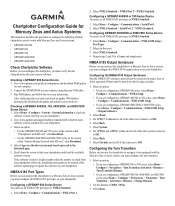
... installation instructions at the bottom of the other system sentences to Off. 7. Scroll down the screen to your chartplotter. Select Home > Configure > Communications > NMEA Port 1. 2. Select NMEA Standard > Serial Port 2 > NMEA Standard. Set GPRMB and GPRMC to On, and set all of the sentences to Off. Select Garmin, and set all of the other route sentences to check the software version currently on only if using the mini-USB cable. 3. Checking a GPSMAP 600 Series...
... installation instructions at the bottom of the other system sentences to Off. 7. Scroll down the screen to your chartplotter. Select Home > Configure > Communications > NMEA Port 1. 2. Select NMEA Standard > Serial Port 2 > NMEA Standard. Set GPRMB and GPRMC to On, and set all of the sentences to Off. Select Garmin, and set all of the other route sentences to check the software version currently on only if using the mini-USB cable. 3. Checking a GPSMAP 600 Series...
Installation Instructions
Page 1
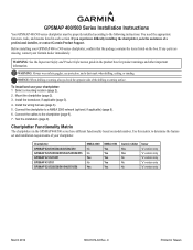
... need the appropriate fasteners, tools, and mounts listed in Taiwan C Printed in each section. GPSMAP 400/500 Series Installation Instructions Your GPSMAP 400/500 series chartplotter must be properly installed according to a NMEA 2000 network (optional, if applicable) (page 8). 6. If you experience difficulty installing the chartplotter, seek the assistance of the drilling or cutting surface. To install and use your Garmin dealer immediately. Connect the cables to determine the feature set...
... need the appropriate fasteners, tools, and mounts listed in Taiwan C Printed in each section. GPSMAP 400/500 Series Installation Instructions Your GPSMAP 400/500 series chartplotter must be properly installed according to a NMEA 2000 network (optional, if applicable) (page 8). 6. If you experience difficulty installing the chartplotter, seek the assistance of the drilling or cutting surface. To install and use your Garmin dealer immediately. Connect the cables to determine the feature set...
Installation Instructions
Page 6
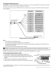
... Specifications on page 10 for normal operation of the chartplotter. Install or check the 3 A fuse (in the in ) > > Green White Orange Yellow CANet L (if applicable) CANet H (if applicable) Accessory on the fuse block. • Do not cut the transducer cable, because this can be connected for more information. 6 GPSMAP 400/500 Series Installation Instructions Refer to an unused holder on Alarm low To transducer (if applicable) GPSMAP 400/500 Series Wiring Harness Notes: • Use...
... Specifications on page 10 for normal operation of the chartplotter. Install or check the 3 A fuse (in the in ) > > Green White Orange Yellow CANet L (if applicable) CANet H (if applicable) Accessory on the fuse block. • Do not cut the transducer cable, because this can be connected for more information. 6 GPSMAP 400/500 Series Installation Instructions Refer to an unused holder on Alarm low To transducer (if applicable) GPSMAP 400/500 Series Wiring Harness Notes: • Use...

Installation Instructions
Page 7
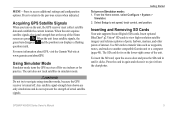
... alert when the chartplotter displays a message. Refer to the wiring diagram of the NMEA 0183 device, and the brown (NMEA 0183 port 1 in ) NMEA Rx/A (+) > NMEA Tx/A (+) NMEA 0183 compliant device > > Wiring a GPSMAP 400/500 Series Chartplotter to a Standard NMEA 0183 Device To connect the wiring harness to a NMEA 0183 device: 1. Set the serial port(s) on the wiring harness of your NMEA 0183 device. GPSMAP 400/500 Series Installation Instructions 7 See the GPSMAP 400/500 Series Owner's Manual for more information. Connecting the Wiring Harness to an...
... alert when the chartplotter displays a message. Refer to the wiring diagram of the NMEA 0183 device, and the brown (NMEA 0183 port 1 in ) NMEA Rx/A (+) > NMEA Tx/A (+) NMEA 0183 compliant device > > Wiring a GPSMAP 400/500 Series Chartplotter to a Standard NMEA 0183 Device To connect the wiring harness to a NMEA 0183 device: 1. Set the serial port(s) on the wiring harness of your NMEA 0183 device. GPSMAP 400/500 Series Installation Instructions 7 See the GPSMAP 400/500 Series Owner's Manual for more information. Connecting the Wiring Harness to an...
Owner's Manual
Page 11
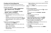
... navigate using simulator mode, because the GPS receiver is on the lower-right corner of interest. From the Home screen, select Configure > System > Simulator. 2. Select Setup to another compatible Garmin unit or a computer (page 40). Use SD cards to transfer data such as waypoints, routes, and tracks to set speed, track control, and position. Press the card in until it from the chartplotter. Acquiring GPS Satellite Signals When you turn on the unit, the GPS receiver must collect satellite data and establish the current location. Insert optional BlueChart...
... navigate using simulator mode, because the GPS receiver is on the lower-right corner of interest. From the Home screen, select Configure > System > Simulator. 2. Select Setup to another compatible Garmin unit or a computer (page 40). Use SD cards to transfer data such as waypoints, routes, and tracks to set speed, track control, and position. Press the card in until it from the chartplotter. Acquiring GPS Satellite Signals When you turn on the unit, the GPS receiver must collect satellite data and establish the current location. Insert optional BlueChart...
Owner's Manual
Page 31
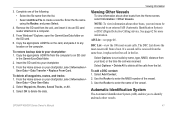
From the Home screen, select Charts > Navigation Chart > MENU > Waypoints & Tracks > New Waypoint. OR From the Home screen, select Information > User Data > Waypoints. 2. Select the waypoint on the Navigation chart. OR From the Home screen, select Information > User Data > Waypoints > Options > New Waypoint. 2. From the Navigation chart, use the Rocker to move the pointer to the location where you want to edit. 4. Select the waypoint you want to change (Name, Symbol, Depth, Water Temp, Comment, or Position). Select Review. (The Review button is only shown when more than...
From the Home screen, select Charts > Navigation Chart > MENU > Waypoints & Tracks > New Waypoint. OR From the Home screen, select Information > User Data > Waypoints. 2. Select the waypoint on the Navigation chart. OR From the Home screen, select Information > User Data > Waypoints > Options > New Waypoint. 2. From the Navigation chart, use the Rocker to move the pointer to the location where you want to edit. 4. Select the waypoint you want to change (Name, Symbol, Depth, Water Temp, Comment, or Position). Select Review. (The Review button is only shown when more than...
Owner's Manual
Page 47
... restore backup data to a computer. 5. Select OK to enter the MMSI number of the vessel. Viewing Information Viewing Other Vessels To view information about other vessels. See page 62 for more information. Select Add Contact. 2. Automatic Identification System The Automatic Identification System (AIS) enables you to any location on the card, and paste it into your chartplotter, select Information > User Data > Data Transfer > Replace From Card. GPSMAP 400/500 Series Owner's Manual 41 Enter the file...
... restore backup data to a computer. 5. Select OK to enter the MMSI number of the vessel. Viewing Information Viewing Other Vessels To view information about other vessels. See page 62 for more information. Select Add Contact. 2. Automatic Identification System The Automatic Identification System (AIS) enables you to any location on the card, and paste it into your chartplotter, select Information > User Data > Data Transfer > Replace From Card. GPSMAP 400/500 Series Owner's Manual 41 Enter the file...
Owner's Manual
Page 56
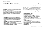
... GPSMAP 400/500 Series Owner's Manual Route Labels-for the Shoreline Distance setting (Nearest, Near, Normal, Far, or Farthest) are indicated by number (Turn 1, Turn 2, and so on) or by waypoint name, or whether the description of the Auto Guidance line. Review the placement of turns is not allowed when using one meter is hidden. The available values for saved routes, this setting while navigating. Configuring the Chartplotter Configuring Navigation Preferences To change this...
... GPSMAP 400/500 Series Owner's Manual Route Labels-for the Shoreline Distance setting (Nearest, Near, Normal, Far, or Farthest) are indicated by number (Turn 1, Turn 2, and so on) or by waypoint name, or whether the description of the Auto Guidance line. Review the placement of turns is not allowed when using one meter is hidden. The available values for saved routes, this setting while navigating. Configuring the Chartplotter Configuring Navigation Preferences To change this...
Owner's Manual
Page 61
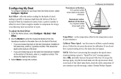
... keel), enter a (-) negative number. Transducer at Surface A (+) positive number shows depth at the bottom of the Keel A (-) negative number shows depth at the Bottom of the keel. Follow the on the bottom of the keel. • If you are measuring down to calibrate a speed-sensing device. GPSMAP 400/500 Series Owner's Manual 55 Keel Offset-offset the surface reading for the temperature sensor of water. From the Home screen, select Configure > My Boat > Keel Offset. 2. Select...
... keel), enter a (-) negative number. Transducer at Surface A (+) positive number shows depth at the bottom of the Keel A (-) negative number shows depth at the Bottom of the keel. Follow the on the bottom of the keel. • If you are measuring down to calibrate a speed-sensing device. GPSMAP 400/500 Series Owner's Manual 55 Keel Offset-offset the surface reading for the temperature sensor of water. From the Home screen, select Configure > My Boat > Keel Offset. 2. Select...
Owner's Manual
Page 68
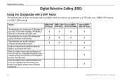
... chartplotter can track the positions of vessels sending position reports. The chartplotter can transfer your Garmin VHF radio. The chartplotter can receive DSC distress and position information from your chartplotter, the radio displays the Distress Call page to your chartplotter to a VHF radio over a NMEA 0183 network or a NMEA 2000 network. Quickly set up and send individual routine call from your radio, the chartplotter displays the manoverboard screen and prompts you connect your radio. Digital Selective Calling Digital Selective Calling (DSC) Using the Chartplotter with DSC...
... chartplotter can track the positions of vessels sending position reports. The chartplotter can transfer your Garmin VHF radio. The chartplotter can receive DSC distress and position information from your chartplotter, the radio displays the Distress Call page to your chartplotter to a VHF radio over a NMEA 0183 network or a NMEA 2000 network. Quickly set up and send individual routine call from your radio, the chartplotter displays the manoverboard screen and prompts you connect your radio. Digital Selective Calling Digital Selective Calling (DSC) Using the Chartplotter with DSC...
Owner's Manual
Page 69
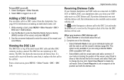
... Review to call . See page 65 for the vessel, and select Trail Line to delete the call . Use the Rocker to enter the Maritime Mobile Service Identity (MMSI) number of the following: • Select Call with Radio to set a waypoint at the time the DSC distress call in distress (page 65). If position information was sent. Select Clear Report to change the line color. While viewing a chart, press MENU > Other...
... Review to call . See page 65 for the vessel, and select Trail Line to delete the call . Use the Rocker to enter the Maritime Mobile Service Identity (MMSI) number of the following: • Select Call with Radio to set a waypoint at the time the DSC distress call in distress (page 65). If position information was sent. Select Clear Report to change the line color. While viewing a chart, press MENU > Other...
Owner's Manual
Page 70
.... DSC Call Information). GPSMAP 400/500 Series Owner's Manual Man-Overboard Distress Calls Initiated from the Chartplotter When your Garmin chartplotter is connected to a Garmin NMEA 2000-compatible radio and you are using NMEA 0183, you to start a Williamson turn to the man-overboard point. For information on activating navigation to a man-overboard location, see your Garmin VHF Radio Owner's Manual. If you have a Garmin autopilot system connected to the network, your chartplotter prompts you can track vessels that send position reports...
.... DSC Call Information). GPSMAP 400/500 Series Owner's Manual Man-Overboard Distress Calls Initiated from the Chartplotter When your Garmin chartplotter is connected to a Garmin NMEA 2000-compatible radio and you are using NMEA 0183, you to start a Williamson turn to the man-overboard point. For information on activating navigation to a man-overboard location, see your Garmin VHF Radio Owner's Manual. If you have a Garmin autopilot system connected to the network, your chartplotter prompts you can track vessels that send position reports...
Owner's Manual
Page 71
... When you connect your Garmin chartplotter to a Garmin VHF NMEA 2000-compatible radio, you have your chartplotter, you can use the chartplotter interface to those channels that channel for a vessel: 1. The selection of the vessel, and a Blue Flag symbol indicating the last reported position. For example, if you call . From a chart screen, press MENU > Other Vessels > DSC > DSC Trails. 2. Select Trail. Select Off to show trails, the Navigation chart displays a black...
... When you connect your Garmin chartplotter to a Garmin VHF NMEA 2000-compatible radio, you have your chartplotter, you can use the chartplotter interface to those channels that channel for a vessel: 1. The selection of the vessel, and a Blue Flag symbol indicating the last reported position. For example, if you call . From a chart screen, press MENU > Other Vessels > DSC > DSC Trails. 2. Select Trail. Select Off to show trails, the Navigation chart displays a black...
Owner's Manual
Page 75
... or Garmin Product Support. GPSMAP 400/500 Series Owner's Manual 69 Alarms and Messages The unit uses an on the data card is lower than the unit can Stop Navigation when this message appears. Contact your dealer or Garmin Product Support if the problem persists. Can't Write User Card, Card May Be Full-error reading card; AIS: Dangerous Target-shows the MMSI (Maritime Mobile Service Identity) of the userset value. Antenna Input is Shorted-a part of the specified distance range...
... or Garmin Product Support. GPSMAP 400/500 Series Owner's Manual 69 Alarms and Messages The unit uses an on the data card is lower than the unit can Stop Navigation when this message appears. Contact your dealer or Garmin Product Support if the problem persists. Can't Write User Card, Card May Be Full-error reading card; AIS: Dangerous Target-shows the MMSI (Maritime Mobile Service Identity) of the userset value. Antenna Input is Shorted-a part of the specified distance range...
Owner's Manual
Page 77
... connected to needs a software update. Sonar Timeout-there is a bad cable or transducer, or the transducer cable was calculated but the starting and ending positions were moved because of safe depth settings. Transfer Complete-the unit has finished uploading or downloading information to have the unit serviced. Sonar Service Incompatible-the external sonar device you entered a saved track name that already exists in the SD card slot. Water Speed Sensor Is Not Working-the speed sensor is full. Route Waypoint Memory Full-no additional route waypoints...
... connected to needs a software update. Sonar Timeout-there is a bad cable or transducer, or the transducer cable was calculated but the starting and ending positions were moved because of safe depth settings. Transfer Complete-the unit has finished uploading or downloading information to have the unit serviced. Sonar Service Incompatible-the external sonar device you entered a saved track name that already exists in the SD card slot. Water Speed Sensor Is Not Working-the speed sensor is full. Route Waypoint Memory Full-no additional route waypoints...

Owner's Manual
Page 80
... 30 Auto Power 48 B backing up data 40 backlight adjusting 3 barometer, reference time 49 Beeper/Display 48 BlueChart g2 Vision using 30-34 boat icon 13 bottom lock 61 buttons 4 C Calibrate Water Speed 55 celestial 38 Chart/Sonar screen using 22 Chart Borders 13 chart data 9 charts detail 12 fish eye 3D 17 fishing 17 mariner's eye 3D 15 navigation 7 settings 11 Clear User Data 39 collision alarm 56 colors, hazard 16 Color Scheme 61 Communications 51 Compass 31 compass rose 12 Compass Tape 9 contact information, Garmin iv coordinates, grid creating waypoints using...
... 30 Auto Power 48 B backing up data 40 backlight adjusting 3 barometer, reference time 49 Beeper/Display 48 BlueChart g2 Vision using 30-34 boat icon 13 bottom lock 61 buttons 4 C Calibrate Water Speed 55 celestial 38 Chart/Sonar screen using 22 Chart Borders 13 chart data 9 charts detail 12 fish eye 3D 17 fishing 17 mariner's eye 3D 15 navigation 7 settings 11 Clear User Data 39 collision alarm 56 colors, hazard 16 Color Scheme 61 Communications 51 Compass 31 compass rose 12 Compass Tape 9 contact information, Garmin iv coordinates, grid creating waypoints using...
Owner's Manual
Page 82
... Port setup 51 Service Points 11 settings alarms 53 chart 11 communications 51 fish eye 3D 17 initializing 2 language 49 navigation preferences 50 system 48 76 units of measure 49 Shoreline Distance 50 simulator 48 mode 5 Skyview 48 software license agreement 73 software version 48 sonar advanced settings 61 cone 17 full screen 57 scroll speed 60 setting up 60-61 setup 60 specifications 68 split frequency 58 split zoom 58 temperature log 59 specifications...
... Port setup 51 Service Points 11 settings alarms 53 chart 11 communications 51 fish eye 3D 17 initializing 2 language 49 navigation preferences 50 system 48 76 units of measure 49 Shoreline Distance 50 simulator 48 mode 5 Skyview 48 software license agreement 73 software version 48 sonar advanced settings 61 cone 17 full screen 57 scroll speed 60 setting up 60-61 setup 60 specifications 68 split frequency 58 split zoom 58 temperature log 59 specifications...

Technical Reference for Garmin NMEA 2000 Products
Page 12
... simplifies installation by other devices on the network, or may use a converter or adapter to function correctly. Power should have an LEN specified on the network. A NMEA 2000 network must be terminated to connect with a nominal voltage of current a device draws from the NMEA 2000 network. 1 LEN = 50 mA. NMEA 2000 Glossary T-connector-Three-way connector with one location. Your existing NMEA 2000 network may both transmit and receive data...
... simplifies installation by other devices on the network, or may use a converter or adapter to function correctly. Power should have an LEN specified on the network. A NMEA 2000 network must be terminated to connect with a nominal voltage of current a device draws from the NMEA 2000 network. 1 LEN = 50 mA. NMEA 2000 Glossary T-connector-Three-way connector with one location. Your existing NMEA 2000 network may both transmit and receive data...


