
Product Manual
Page 5
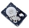
... and the basics of the HDD and the installation environment. PREFACE This manual describes the MBA3300NC, MBA3300NP, MBA3147NC, MBA3147NP, MBA3073NC, and MBA3073NP 3.5-inch SCSI hard disk drives. CHAPTER 3 DATA FORMAT This chapter describes the data structure, the addressing method, and the defect management. CHAPTER 4 INSTALLATION REQUIREMENTS This chapter describes the basic physical and electrical requirements for setting device number and operation modes, mounting the disk drive, connecting the cables, and confirming drive operation.
... and the basics of the HDD and the installation environment. PREFACE This manual describes the MBA3300NC, MBA3300NP, MBA3147NC, MBA3147NP, MBA3073NC, and MBA3073NP 3.5-inch SCSI hard disk drives. CHAPTER 3 DATA FORMAT This chapter describes the data structure, the addressing method, and the defect management. CHAPTER 4 INSTALLATION REQUIREMENTS This chapter describes the basic physical and electrical requirements for setting device number and operation modes, mounting the disk drive, connecting the cables, and confirming drive operation.
Product Manual
Page 7
... last device connected to the product or other property may be careful of the connection position of the SCSI connectors. When the recommended parts listed in Table 4.2 are as follows: Task Installation A hazardous situation could result in minor or moderate personal injury if the user does not perform the procedure correctly. Data loss 1. Do not change the setting of terminals except following setting pins during operation...
... last device connected to the product or other property may be careful of the connection position of the SCSI connectors. When the recommended parts listed in Table 4.2 are as follows: Task Installation A hazardous situation could result in minor or moderate personal injury if the user does not perform the procedure correctly. Data loss 1. Do not change the setting of terminals except following setting pins during operation...
Product Manual
Page 12
... 68-pin connector type 16-bit SCSI model (NP model 60 Cable connector requirements 67 External operator panel (on NP model drives only 68 CHAPTER 5 INSTALLATION 71 5.1 Notes on Handling HDDs 71 5.2 Connections...73 5.3 Setting Terminals ...75 5.3.1 SCSI ID setting...76 5.3.2 Each mode setting ...78 5.3.3 Mode settings ...80 5.4 Mounting HDDs...81 5.4.1 Check before mounting ...81 5.4.2 Mounting procedures...81 5.5 Connecting Cables...82 5.6 Checking Operation after Installation and Preparing the HDDs for Use 83 5.6.1 Confirming initial operations 83 5.6.2 Checking SCSI connection 84...
... 68-pin connector type 16-bit SCSI model (NP model 60 Cable connector requirements 67 External operator panel (on NP model drives only 68 CHAPTER 5 INSTALLATION 71 5.1 Notes on Handling HDDs 71 5.2 Connections...73 5.3 Setting Terminals ...75 5.3.1 SCSI ID setting...76 5.3.2 Each mode setting ...78 5.3.3 Mode settings ...80 5.4 Mounting HDDs...81 5.4.1 Check before mounting ...81 5.4.2 Mounting procedures...81 5.5 Connecting Cables...82 5.6 Checking Operation after Installation and Preparing the HDDs for Use 83 5.6.1 Confirming initial operations 83 5.6.2 Checking SCSI connection 84...

Product Manual
Page 14
... noise filter (recommended 58 NC connectors location ...58 SCA2 type 16-bit SCSI connector 59 NP connectors and terminals location 60 68-pin type 16-bit SCSI interface connector 61 Power supply connector (68-pin type 16-bit SCSI 61 External operator panel connector (CN1 62 External operator panel connector (CN2 62 16-bit SCSI ID external input 63 Output signal for external LED 65 SCSI cables connection ...66 10 Downloaded from www.Manualslib.com manuals search engine C141-E270
... noise filter (recommended 58 NC connectors location ...58 SCA2 type 16-bit SCSI connector 59 NP connectors and terminals location 60 68-pin type 16-bit SCSI interface connector 61 Power supply connector (68-pin type 16-bit SCSI 61 External operator panel connector (CN1 62 External operator panel connector (CN2 62 16-bit SCSI ID external input 63 Output signal for external LED 65 SCSI cables connection ...66 10 Downloaded from www.Manualslib.com manuals search engine C141-E270
Product Manual
Page 16
... setting...77 Setting SCSI terminator power supply (NP model 78 Motor start mode setting...78 Write protect setting (NP model 79 Setting of the SCSI interface operation mode (NP model 79 Setting the bus width of the SCSI interface (NP model 79 Default mode settings (by CHANGE DEFINITION command 80 Setting check list (NP model only 81 Table 6.1 Table 6.2 Table 6.3 Self-diagnostic functions ...95 System-level field troubleshooting 106 HDD troubleshooting ...107 Table 7.1 Definition of sense data ...115 Table A.1 CN2 setting terminal (on NP model drives...
... setting...77 Setting SCSI terminator power supply (NP model 78 Motor start mode setting...78 Write protect setting (NP model 79 Setting of the SCSI interface operation mode (NP model 79 Setting the bus width of the SCSI interface (NP model 79 Default mode settings (by CHANGE DEFINITION command 80 Setting check list (NP model only 81 Table 6.1 Table 6.2 Table 6.3 Self-diagnostic functions ...95 System-level field troubleshooting 106 HDD troubleshooting ...107 Table 7.1 Definition of sense data ...115 Table A.1 CN2 setting terminal (on NP model drives...
Product Manual
Page 30
... V) MBA3300NC MBA3300NP Specification MBA3147NC MBA3147NP ± 5 % 0.5 A MBA3073NC MBA3073NP 1.5 A 0.79 A 250 mVp-p or less (*7) (*1) For detail condition, see Section 4.1. (*2) Vibration applied to be accessed should be distributed over 20 MHz) is less than 100 mVp-p. 2.1.4 Error rate Errors detected during HDD Idle state. (*6) Operating currents are values under random W/R operation of full partition at the HDD connector side during initialization and replaced by alternate...
... V) MBA3300NC MBA3300NP Specification MBA3147NC MBA3147NP ± 5 % 0.5 A MBA3073NC MBA3073NP 1.5 A 0.79 A 250 mVp-p or less (*7) (*1) For detail condition, see Section 4.1. (*2) Vibration applied to be accessed should be distributed over 20 MHz) is less than 100 mVp-p. 2.1.4 Error rate Errors detected during HDD Idle state. (*6) Operating currents are values under random W/R operation of full partition at the HDD connector side during initialization and replaced by alternate...

Product Manual
Page 31
... if the HDD is used intermittently, the longest service life is 5 years. 2.1.5 Reliability (1) Mean Time Between Failures (MTBF) MTBF of the HDDs during its lifetime is six months. The maximum storage period without turning the power on the environment temperature. Note: The MTBF is as low as : MTBF= Operating time (hours) at case DE surface temperature above 50°C may degrade product reliability. C141-E270 27 Downloaded from...
... if the HDD is used intermittently, the longest service life is 5 years. 2.1.5 Reliability (1) Mean Time Between Failures (MTBF) MTBF of the HDDs during its lifetime is six months. The maximum storage period without turning the power on the environment temperature. Note: The MTBF is as low as : MTBF= Operating time (hours) at case DE surface temperature above 50°C may degrade product reliability. C141-E270 27 Downloaded from...
Product Manual
Page 42
... number of the spare sector area. Table 3.1 Format capacity Model Data block length User blocks Format capacity MBA3300NC, MBA3300NP 585,937,500 300 GB (*) MBA3147NC, MBA3147NP 512 287,277,984 147 GB (*) MBA3073NC, MBA3073NP 143,638,992 73.5 GB (*) (*) One gigabyte (GB) = one billion bytes; The initiator specifies the data to each physical sector at formatting. accessible capacity will be used . Data on the operating environment and formatting. Table 3.1 lists examples of that data. 38 Downloaded...
... number of the spare sector area. Table 3.1 Format capacity Model Data block length User blocks Format capacity MBA3300NC, MBA3300NP 585,937,500 300 GB (*) MBA3147NC, MBA3147NP 512 287,277,984 147 GB (*) MBA3073NC, MBA3073NP 143,638,992 73.5 GB (*) (*) One gigabyte (GB) = one billion bytes; The initiator specifies the data to each physical sector at formatting. accessible capacity will be used . Data on the operating environment and formatting. Table 3.1 lists examples of that data. 38 Downloaded...

Product Manual
Page 49
... sectors and, - When an error is detected in a data block in the data area, recovery data is rewritten and verified in Mode Parameter). C141-E270 45 Downloaded from www.Manualslib.com manuals search engine the sectors which will not be made AWRE shall be made for the sector that has already been re-assigned. 2) Application requirements / processing When WRITE/WRITE EXTENDED command detects any Servo error...
... sectors and, - When an error is detected in a data block in the data area, recovery data is rewritten and verified in Mode Parameter). C141-E270 45 Downloaded from www.Manualslib.com manuals search engine the sectors which will not be made AWRE shall be made for the sector that has already been re-assigned. 2) Application requirements / processing When WRITE/WRITE EXTENDED command detects any Servo error...

Product Manual
Page 75
... the following after turning off the power. CHAPTER 5 INSTALLATION 5.1 Notes on Handling HDDs 5.2 Connections 5.3 Setting Terminals 5.4 Mounting HDDs 5.5 Connecting Cables 5.6 Checking Operation after Installation and Preparing the HDDs for Use 5.7 Dismounting HDDs This chapter describes the notes on handling HDDs, connections, setting switches and plugs, mounting HDDs, connecting cables, confirming drive operations after installation and preparation for use, and dismounting HDDs. 5.1 Notes on the PCBAs except setting terminal (CN1 and CN2). b) Do not leave the...
... the following after turning off the power. CHAPTER 5 INSTALLATION 5.1 Notes on Handling HDDs 5.2 Connections 5.3 Setting Terminals 5.4 Mounting HDDs 5.5 Connecting Cables 5.6 Checking Operation after Installation and Preparing the HDDs for Use 5.7 Dismounting HDDs This chapter describes the notes on handling HDDs, connections, setting switches and plugs, mounting HDDs, connecting cables, confirming drive operations after installation and preparation for use, and dismounting HDDs. 5.1 Notes on the PCBAs except setting terminal (CN1 and CN2). b) Do not leave the...
Product Manual
Page 76
...use one of all maintenance work area. b) Be careful not to give excess pressure to the internal unit when removing cushions. b) Minimize the delivery distance after power is not operating. For the carrying direction at delivery (for any labels from www.Manualslib.com manuals search engine C141-E270 Check that the HDD is on hard... sign side is recommended to connect or disconnect connections when power is free from the Fcell (See Figure 6.2). b) It is up. b) The storage environment must satisfy the requirements specified in temperature. 72 Downloaded from the HDD.
...use one of all maintenance work area. b) Be careful not to give excess pressure to the internal unit when removing cushions. b) Minimize the delivery distance after power is not operating. For the carrying direction at delivery (for any labels from www.Manualslib.com manuals search engine C141-E270 Check that the HDD is on hard... sign side is recommended to connect or disconnect connections when power is free from the Fcell (See Figure 6.2). b) It is up. b) The storage environment must satisfy the requirements specified in temperature. 72 Downloaded from the HDD.

Product Manual
Page 79
... when the device is included in this section. Pin 2 CN2 Pin 24 Pin 1 Pin 23 Figure 5.2 Setting terminals location (on . • Write protect: Pin pair 9/10 of the setting terminal for NP model, and Figure 5.3 shows the allocation and the default settings for NC model because the setting terminal is shipped from www.Manualslib.com manuals search engine CAUTION Data loss 1. Do not change setting status set at factory shipment...
... when the device is included in this section. Pin 2 CN2 Pin 24 Pin 1 Pin 23 Figure 5.2 Setting terminals location (on . • Write protect: Pin pair 9/10 of the setting terminal for NP model, and Figure 5.3 shows the allocation and the default settings for NC model because the setting terminal is shipped from www.Manualslib.com manuals search engine CAUTION Data loss 1. Do not change setting status set at factory shipment...

Product Manual
Page 91
... the HDD is formatted with the MODE SELECT or MODE SELECT EXTENDED command. In this case, the currently set value is installed in the user space This section outlines the formatting at abnormal end a) When sense data can change the following items for the SCSI cable connection: • All connectors including other SCSI devices are as follows. a. c) Check the setting of the SCSI Logical Interface Specifications for each model (part number) when shipped from www.Manualslib.com manuals...
... the HDD is formatted with the MODE SELECT or MODE SELECT EXTENDED command. In this case, the currently set value is installed in the user space This section outlines the formatting at abnormal end a) When sense data can change the following items for the SCSI cable connection: • All connectors including other SCSI devices are as follows. a. c) Check the setting of the SCSI Logical Interface Specifications for each model (part number) when shipped from www.Manualslib.com manuals...

Product Manual
Page 93
... reset. The MODE SELECT parameter is not saved for each SCSI ID of the disk is performed by the user when power is effective as long as the common parameter for all IDs. C141-E270 89 Downloaded from the initiator. To obtain the best performance, set or saved with the default values, the operations are assured with the MODE SELECT or MODE SELECT EXTENDED command, the HDD sets the default values for parameters and operates...
... reset. The MODE SELECT parameter is not saved for each SCSI ID of the disk is performed by the user when power is effective as long as the common parameter for all IDs. C141-E270 89 Downloaded from the initiator. To obtain the best performance, set or saved with the default values, the operations are assured with the MODE SELECT or MODE SELECT EXTENDED command, the HDD sets the default values for parameters and operates...

Product Manual
Page 95
... normal operations. (2) Disconnection/reconnection parameters (page code = 2) The following performance factors of the system: • Time required for reconnection processing • Average data transfer rate of the SCSI bus • Average amount of processing data specified with a command Refer to Chapter 2 "Data Buffer Management" of the SCSI Logical Interface Specifications for how to transfer data on the SCSI bus at a read (READ or READ EXTENDED command) or write operation (WRITE, WRITE EXTENDED, or WRITE AND VERIFY command) of...
... normal operations. (2) Disconnection/reconnection parameters (page code = 2) The following performance factors of the system: • Time required for reconnection processing • Average data transfer rate of the SCSI bus • Average amount of processing data specified with a command Refer to Chapter 2 "Data Buffer Management" of the SCSI Logical Interface Specifications for how to transfer data on the SCSI bus at a read (READ or READ EXTENDED command) or write operation (WRITE, WRITE EXTENDED, or WRITE AND VERIFY command) of...
Product Manual
Page 105
Generally, the following information must be included: a) HDD model, part number (P/N), revision number, serial number (S/N), and date of manufacturing b) Error status • Date when the error occurred • System configuration • Environmental conditions (temperature, humidity, and voltage) c) Error history d) Error contents • Outline of inconvenience • Issued commands and specified parameters • Sense data • Other error analysis information See Section 5.1 for notes on packing and handling when returning the disk drive. 6.2.3 Maintenance levels If...
Generally, the following information must be included: a) HDD model, part number (P/N), revision number, serial number (S/N), and date of manufacturing b) Error status • Date when the error occurred • System configuration • Environmental conditions (temperature, humidity, and voltage) c) Error history d) Error contents • Outline of inconvenience • Issued commands and specified parameters • Sense data • Other error analysis information See Section 5.1 for notes on packing and handling when returning the disk drive. 6.2.3 Maintenance levels If...
Product Manual
Page 110
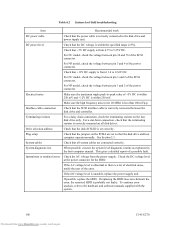
... NC model, check the voltage between pin 1 and 2 of the SCSI connector. For NP model, check the voltage between the disk drive and controller. Electrical noise Make sure the maximum ripple peak-to the hardware and software manuals supplied with the system. 106 Downloaded from the power supply. If the AC voltage level is abnormal or there is correctly connected between pin 3 and 4 of the SCSI connector. Plug setup Check that the SCSI interface cable is...
... NC model, check the voltage between pin 1 and 2 of the SCSI connector. For NP model, check the voltage between the disk drive and controller. Electrical noise Make sure the maximum ripple peak-to the hardware and software manuals supplied with the system. 106 Downloaded from the power supply. If the AC voltage level is abnormal or there is correctly connected between pin 3 and 4 of the SCSI connector. Plug setup Check that the SCSI interface cable is...

Product Manual
Page 130
P/N PCBA PER PLO Sync PMI P Parts/Number Printed Circuit Board Assembly Post ERror Phase Lock Oscillator Syncronous Partial Medium Indicator RCD REQ RH RST R Read Cache Disable REQuest Relative Humidity ReSeT S/N SCSI SCT SEL SelfTest SG SP SPM S Serial/Number Small Computer System Interface SeCTor SELect Self Test Signal Ground Save Page SPindle Motor TB TPI UnitOfl T Transfer Block Tracks Per Inch U Unit Offline VCM V Voice Coil Motor WCE W Write Cache Enable 126 Downloaded from www.Manualslib.com manuals search engine C141-E270
P/N PCBA PER PLO Sync PMI P Parts/Number Printed Circuit Board Assembly Post ERror Phase Lock Oscillator Syncronous Partial Medium Indicator RCD REQ RH RST R Read Cache Disable REQuest Relative Humidity ReSeT S/N SCSI SCT SEL SelfTest SG SP SPM S Serial/Number Small Computer System Interface SeCTor SELect Self Test Signal Ground Save Page SPindle Motor TB TPI UnitOfl T Transfer Block Tracks Per Inch U Unit Offline VCM V Voice Coil Motor WCE W Write Cache Enable 126 Downloaded from www.Manualslib.com manuals search engine C141-E270

Product Manual
Page 132
... maintenance 101 finding possibly faulty part 108 format capacity 38 format parameter 88 FORMAT UNIT command 88 formatting 87 G gaps 37 general note 71 H hardware function test 96 hardware structure 18 HDD replacement 101 HDD troubleshooting 107 head 18 head skew 35 high speed data transfer 15 high speed positioning 17 I initial seek operation check 104 initial self-diagnostic 96 installation 71, 72 installation requirement 47 interface test 99 internal test space 33 L large capacity 17 leak magnetic flux...
... maintenance 101 finding possibly faulty part 108 format capacity 38 format parameter 88 FORMAT UNIT command 88 formatting 87 G gaps 37 general note 71 H hardware function test 96 hardware structure 18 HDD replacement 101 HDD troubleshooting 107 head 18 head skew 35 high speed data transfer 15 high speed positioning 17 I initial seek operation check 104 initial self-diagnostic 96 installation 71, 72 installation requirement 47 interface test 99 internal test space 33 L large capacity 17 leak magnetic flux...
Product Manual
Page 133
... type SCSI connector 59 SCSI bus configuration 20 SCSI bus connection 74 SCSI cable connection 66 SCSI connector 120, 121 SCSI connector signal allocation............120, 121 SCSI function specification 29 SCSI ID setting 76, 77 SCSI interface error 116 SCSI standard 14 sector format 36 seek test 96 self-diagnostic 95 self-diagnostic function 95 SEND DIAGNOSTIC command 97 sense data 113, 116 sense data analysis 115 sense data collection 113 sense data format 114 sense key 113 service life 100 service system 101 setting bus width of SCSI interface...
... type SCSI connector 59 SCSI bus configuration 20 SCSI bus connection 74 SCSI cable connection 66 SCSI connector 120, 121 SCSI connector signal allocation............120, 121 SCSI function specification 29 SCSI ID setting 76, 77 SCSI interface error 116 SCSI standard 14 sector format 36 seek test 96 self-diagnostic 95 self-diagnostic function 95 SEND DIAGNOSTIC command 97 sense data 113, 116 sense data analysis 115 sense data collection 113 sense data format 114 sense key 113 service life 100 service system 101 setting bus width of SCSI interface...


