

Manual/User Guide
Page 2
... on such specialized use in this product. IMPORTANT NOTE TO USERS READ THE ENTIRE MANUAL CAREFULLY BEFORE USING THIS PRODUCT. While FUJITSU has sought to ensure the accuracy of This manual This manual contains important information for using the product. Moreover, they are...support, or weapons firing controls) where particularly high reliability requirements exist, where the pertinent levels of Fujitsu Limited. The contents of this manual. In addition, FUJITSU assumes no liability to the application or use of these products for incidental or consequential damages arising ...
... on such specialized use in this product. IMPORTANT NOTE TO USERS READ THE ENTIRE MANUAL CAREFULLY BEFORE USING THIS PRODUCT. While FUJITSU has sought to ensure the accuracy of This manual This manual contains important information for using the product. Moreover, they are...support, or weapons firing controls) where particularly high reliability requirements exist, where the pertinent levels of Fujitsu Limited. The contents of this manual. In addition, FUJITSU assumes no liability to the application or use of these products for incidental or consequential damages arising ...
Manual/User Guide
Page 4
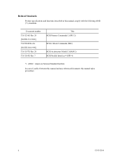
Document number T10/1236D Rev.20 [NCITS.351:2001] T10/996D Rev.8c [NCITS.306:1998] T10/1157D Rev.20 T10/1365D Rev.7 Title SCSI Primary Commands-2 (SPC-2) SCSI-3 Block Commands (SBC) SCSI Architecture Model-2 (SAM-2) SCSI Parallel Interface-4 (SPI-4) *1 ANSI = American National Standard Institute In case of conflict between this manual and any referenced document, this manual comply with the following ANSI (*1) standards. Related Standards Product specifications and functions described in this manual takes precedence. ii C141-E166
Document number T10/1236D Rev.20 [NCITS.351:2001] T10/996D Rev.8c [NCITS.306:1998] T10/1157D Rev.20 T10/1365D Rev.7 Title SCSI Primary Commands-2 (SPC-2) SCSI-3 Block Commands (SBC) SCSI Architecture Model-2 (SAM-2) SCSI Parallel Interface-4 (SPI-4) *1 ANSI = American National Standard Institute In case of conflict between this manual and any referenced document, this manual comply with the following ANSI (*1) standards. Related Standards Product specifications and functions described in this manual takes precedence. ii C141-E166
Manual/User Guide
Page 5
...items and the signal assignments of the MAP series disk drives and their use the other manuals. PREFACE This manual describes the MAP3147NC/NP, MAP3735NC/NP and MAP3367NC/NP (hereafter, MAP series), 3.5 type fixed disk drives with an embedded SCSI controller. This manual is written for... installing MAP series disk drives. APPENDIX A to do about media defects. The need arises, use...
...items and the signal assignments of the MAP series disk drives and their use the other manuals. PREFACE This manual describes the MAP3147NC/NP, MAP3735NC/NP and MAP3367NC/NP (hereafter, MAP series), 3.5 type fixed disk drives with an embedded SCSI controller. This manual is written for... installing MAP series disk drives. APPENDIX A to do about media defects. The need arises, use...
Manual/User Guide
Page 6
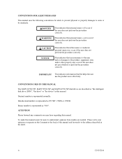
CAUTION This indicates that inconvenience to the user such as "the intelligent disk drive (IDD)", "the drive" or "the device" in the sheet. Decimal number is represented as "010". NOTICE This indicates that either minor or moderate personal injury may ...personal injury will occur if the user does not perform the procedure correctly. CONVENTIONS USED IN THIS MANUAL The MAP3147NC/NP, MAP3735NC/NP and MAP3367NC/NP disk drives are needed. To make this manual and forward it to the address described in this manual. Hexadecimal number is represented normally. Please write...
CAUTION This indicates that inconvenience to the user such as "the intelligent disk drive (IDD)", "the drive" or "the device" in the sheet. Decimal number is represented as "010". NOTICE This indicates that either minor or moderate personal injury may ...personal injury will occur if the user does not perform the procedure correctly. CONVENTIONS USED IN THIS MANUAL The MAP3147NC/NP, MAP3735NC/NP and MAP3367NC/NP disk drives are needed. To make this manual and forward it to the address described in this manual. Hexadecimal number is represented normally. Please write...
Manual/User Guide
Page 7
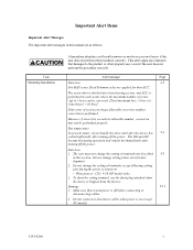
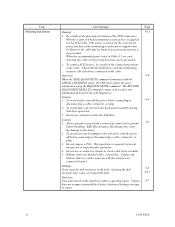
... of read sector keeps allowable error byte number, correction is shipped from the factory. Damage 5-11 1. Hot temperature To prevent injury, do not handle the drive until after the device has 5-1 cooled sufficiently after turning off the power. Do not change setting status set at factory shipment. 2. Data loss 1. To short...
... of read sector keeps allowable error byte number, correction is shipped from the factory. Damage 5-11 1. Hot temperature To prevent injury, do not handle the drive until after the device has 5-1 cooled sufficiently after turning off the power. Do not change setting status set at factory shipment. 2. Data loss 1. To short...
Manual/User Guide
Page 8
...Do not use solvents to the cable. Fujitsu 6-7 does not assume responsibility if data is turned on the disk drive before handling. vi C141-E166 This operation is the last device connected to clean the disk drive. Be careful of the insertion orientation of...Task Mounting Installation Alert message Page Damage 5-11 1. Check that the SCSI device with the terminating resistor is required to clean a disk drive assembly. 5. Do not use a conductive cleaner to prevent unexpected or unpredictable operation. 4. Always ground yourself with the colored wire connected to...
...Do not use solvents to the cable. Fujitsu 6-7 does not assume responsibility if data is turned on the disk drive before handling. vi C141-E166 This operation is the last device connected to clean the disk drive. Be careful of the insertion orientation of...Task Mounting Installation Alert message Page Damage 5-11 1. Check that the SCSI device with the terminating resistor is required to clean a disk drive assembly. 5. Do not use a conductive cleaner to prevent unexpected or unpredictable operation. 4. Always ground yourself with the colored wire connected to...

Manual/User Guide
Page 10
This page is intentionally left blank.
This page is intentionally left blank.
Manual/User Guide
Page 11
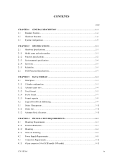
CONTENTS page CHAPTER 1 GENERAL DESCRIPTION 1-1 1.1 Standard Features ...1-2 1.2 Hardware Structure...1-6 1.3 System Configuration ...1-9 CHAPTER 2 SPECIFICATIONS 2-1 2.1 Hardware Specifications...2-1 2.1.1 Model name and order number 2-1 2.1.2 Function specifications...2-2 2.1.3 Environmental specifications 2-4 2.1.4 Error rate ...2-5 2.1.5 Reliability...2-5 2.2 SCSI Function Specifications 2-7 CHAPTER 3 DATA FORMAT 3-1 3.1 Data Space...3-1 3.1.1 Cylinder configuration...3-1 3.1.2 Alternate spare area...3-4 3.1.3 Track format...3-5 3.1.4 Sector format ...3-7 3.1.5 Format capacity ...
CONTENTS page CHAPTER 1 GENERAL DESCRIPTION 1-1 1.1 Standard Features ...1-2 1.2 Hardware Structure...1-6 1.3 System Configuration ...1-9 CHAPTER 2 SPECIFICATIONS 2-1 2.1 Hardware Specifications...2-1 2.1.1 Model name and order number 2-1 2.1.2 Function specifications...2-2 2.1.3 Environmental specifications 2-4 2.1.4 Error rate ...2-5 2.1.5 Reliability...2-5 2.2 SCSI Function Specifications 2-7 CHAPTER 3 DATA FORMAT 3-1 3.1 Data Space...3-1 3.1.1 Cylinder configuration...3-1 3.1.2 Alternate spare area...3-4 3.1.3 Track format...3-5 3.1.4 Sector format ...3-7 3.1.5 Format capacity ...
Manual/User Guide
Page 12
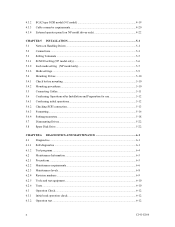
...only 5-6 5.3.2 Each mode setting (NP model only 5-7 5.3.3 Mode settings ...5-9 5.4 Mounting Drives...5-10 5.4.1 Check before mounting ...5-10 5.4.2 Mounting procedures...5-10 5.5 Connecting Cables...5-11 5.6 Confirming ...use 5-12 5.6.1 Confirming initial operations 5-12 5.6.2 Checking SCSI connection 5-13 5.6.3 Formatting ...5-16 5.6.4 Setting parameters ...5-18 5.7 Dismounting Drives...5-22 5.8 Spare Disk Drive ...5-22 CHAPTER 6 DIAGNOSTICS AND MAINTENANCE 6-1 6.1 Diagnostics ...6-1 6.1.1 Self-diagnostics ...6-1 6.1.2 Test programs...6-4 6.2 Maintenance Information 6-5 6.2.1 Precautions...
...only 5-6 5.3.2 Each mode setting (NP model only 5-7 5.3.3 Mode settings ...5-9 5.4 Mounting Drives...5-10 5.4.1 Check before mounting ...5-10 5.4.2 Mounting procedures...5-10 5.5 Connecting Cables...5-11 5.6 Confirming ...use 5-12 5.6.1 Confirming initial operations 5-12 5.6.2 Checking SCSI connection 5-13 5.6.3 Formatting ...5-16 5.6.4 Setting parameters ...5-18 5.7 Dismounting Drives...5-22 5.8 Spare Disk Drive ...5-22 CHAPTER 6 DIAGNOSTICS AND MAINTENANCE 6-1 6.1 Diagnostics ...6-1 6.1.1 Self-diagnostics ...6-1 6.1.2 Test programs...6-4 6.2 Maintenance Information 6-5 6.2.1 Precautions...
Manual/User Guide
Page 13
6.3.3 6.4 6.4.1 6.4.2 6.4.3 6.4.4 6.4.5 Diagnostic test ...6-12 Troubleshooting Procedures 6-13 Outline of troubleshooting procedures 6-13 Troubleshooting with disk drive replacement in the field 6-13 Troubleshooting at the repair site 6-15 Troubleshooting with parts replacement in the factory 6-16 Finding possibly faulty parts 6-16 CHAPTER 7 ...
6.3.3 6.4 6.4.1 6.4.2 6.4.3 6.4.4 6.4.5 Diagnostic test ...6-12 Troubleshooting Procedures 6-13 Outline of troubleshooting procedures 6-13 Troubleshooting with disk drive replacement in the field 6-13 Troubleshooting at the repair site 6-15 Troubleshooting with parts replacement in the factory 6-16 Finding possibly faulty parts 6-16 CHAPTER 7 ...

Manual/User Guide
Page 14
This page is intentionally left blank.
This page is intentionally left blank.
Manual/User Guide
Page 15
FIGURES Figure 1.1 Figure 1.2 Figure 1.3 Figure 1.4 page NC model drives outer view 1-6 NP model drives outer view 1-6 Disk/head configuration...1-7 System configuration ...1-9 Figure 3.1 Figure 3.2 Figure 3.3 Figure 3.4 Figure 3.5 Figure 3.6 Figure 3.7 Figure 3.8 Cylinder configuration...3-2 Spare area in cell ...3-5 Alternate cylinder ...3-5 Track format ...3-6 ...
FIGURES Figure 1.1 Figure 1.2 Figure 1.3 Figure 1.4 page NC model drives outer view 1-6 NP model drives outer view 1-6 Disk/head configuration...1-7 System configuration ...1-9 Figure 3.1 Figure 3.2 Figure 3.3 Figure 3.4 Figure 3.5 Figure 3.6 Figure 3.7 Figure 3.8 Cylinder configuration...3-2 Spare area in cell ...3-5 Alternate cylinder ...3-5 Track format ...3-6 ...
Manual/User Guide
Page 16
Figure 4.20 Figure 4.21 Figure 4.22 Figure 4.23 SCSI cables connection ...4-18 NC connectors location ...4-19 SCA2 type SCSI connector 4-20 External operator panel circuit example 4-22 Figure 5.1 Figure 5.2 Figure 5.3 Figure 5.4 Figure 5.5 SCSI bus connections ...5-4 Setting terminals location (on NP models only 5-5 CN2 setting terminal (on NP models only 5-6 Checking the SCSI connection (A 5-14 Checking the SCSI connection (B 5-15 Figure 6.1 Figure 6.2 Figure 6.3 Revision label ...6-9 Indicating revision numbers 6-10 Test flowchart...6-11 Figure 7.1 Format of extended sense data...
Figure 4.20 Figure 4.21 Figure 4.22 Figure 4.23 SCSI cables connection ...4-18 NC connectors location ...4-19 SCA2 type SCSI connector 4-20 External operator panel circuit example 4-22 Figure 5.1 Figure 5.2 Figure 5.3 Figure 5.4 Figure 5.5 SCSI bus connections ...5-4 Setting terminals location (on NP models only 5-5 CN2 setting terminal (on NP models only 5-6 Checking the SCSI connection (A 5-14 Checking the SCSI connection (B 5-15 Figure 6.1 Figure 6.2 Figure 6.3 Revision label ...6-9 Indicating revision numbers 6-10 Test flowchart...6-11 Figure 7.1 Format of extended sense data...
Manual/User Guide
Page 17
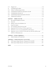
... check list (NP model only 5-10 Table 6.1 Self-diagnostic functions ...6-1 Table 6.2 System-level field troubleshooting 6-14 Table 6.3 Disk drive troubleshooting ...6-15 Table 7.1 Definition of sense data ...7-3 Table A.1 CN2 setting terminal (on NP model drives only A-2 Table B.1 SCSI connector (68 pin type LVD 16-bit SCSI): CN1 B-2 Table B.2 SCSI connector (SCA2 type LVD...
... check list (NP model only 5-10 Table 6.1 Self-diagnostic functions ...6-1 Table 6.2 System-level field troubleshooting 6-14 Table 6.3 Disk drive troubleshooting ...6-15 Table 7.1 Definition of sense data ...7-3 Table A.1 CN2 setting terminal (on NP model drives only A-2 Table B.1 SCSI connector (68 pin type LVD 16-bit SCSI): CN1 B-2 Table B.2 SCSI connector (SCA2 type LVD...

Manual/User Guide
Page 18
This page is intentionally left blank.
This page is intentionally left blank.
Manual/User Guide
Page 19
...from the format at factory shipment by reinitializing with an embedded SCSI controller. IDDs are high performance large capacity 3.5 type fixed disk drives with the user's system. C141-E166 1-1 The flexibility and expandability of the SCSI, as well as described in the ANSI ... manual. Refer to SCSI Logical Interface Specifications for details. The MAP series disk drives support the Small Computer System Interface (SCSI) as the powerful command set of the MAP series intelligent disk drives (IDD). CHAPTER 1 GENERAL DESCRIPTION 1.1 Standard Features 1.2 Hardware Structure 1.3 System ...
...from the format at factory shipment by reinitializing with an embedded SCSI controller. IDDs are high performance large capacity 3.5 type fixed disk drives with the user's system. C141-E166 1-1 The flexibility and expandability of the SCSI, as well as described in the ANSI ... manual. Refer to SCSI Logical Interface Specifications for details. The MAP series disk drives support the Small Computer System Interface (SCSI) as the powerful command set of the MAP series intelligent disk drives (IDD). CHAPTER 1 GENERAL DESCRIPTION 1.1 Standard Features 1.2 Hardware Structure 1.3 System ...
Manual/User Guide
Page 20
... for SCSI-2. 8-bit data bus is available only with the large capacity buffer in the standard 3.5 type fixed disk drive form factor, the IDD is 320 MB/s maximum at the paced transfer synchronous mode. 1-2 C141-E166 This allows software...of connectable SCSI devices on the same SCSI bus is varied as follows. • 8-bit SCSI: 8 drives max. (option for NP model) • 16-bit SCSI: 16 drives max. (4) High speed data transfer Such a high data transfer rate on the SCSI bus is extremely ...width (16-bit SCSI), which have the wide transfer function suitable for details of the disk drive.
... for SCSI-2. 8-bit data bus is available only with the large capacity buffer in the standard 3.5 type fixed disk drive form factor, the IDD is 320 MB/s maximum at the paced transfer synchronous mode. 1-2 C141-E166 This allows software...of connectable SCSI devices on the same SCSI bus is varied as follows. • 8-bit SCSI: 8 drives max. (option for NP model) • 16-bit SCSI: 16 drives max. (4) High speed data transfer Such a high data transfer rate on the SCSI bus is extremely ...width (16-bit SCSI), which have the wide transfer function suitable for details of the disk drive.
Manual/User Guide
Page 21
... data blocks is surely terminated with utilizing high data transfer capability of the SCSI bus regardless of actual data transfer rate of the disk drive. (7) Cache feature After executing the READ command, the IDD reads automatically and stores (prefetches) the subsequent data blocks into the data ... This feature provides the suitable usage environment for users. This feature realizes the high speed processing. To ensure it, you turn off the drive's power. C141-E166 1-3 Note: The maximum data transfer rate in asynchronous mode may be achieved by transferring the data from the data ...
... data blocks is surely terminated with utilizing high data transfer capability of the SCSI bus regardless of actual data transfer rate of the disk drive. (7) Cache feature After executing the READ command, the IDD reads automatically and stores (prefetches) the subsequent data blocks into the data ... This feature provides the suitable usage environment for users. This feature realizes the high speed processing. To ensure it, you turn off the drive's power. C141-E166 1-3 Note: The maximum data transfer rate in asynchronous mode may be achieved by transferring the data from the data ...
Manual/User Guide
Page 22
... recoverable data check occurs, error-free data can be transferred to the following values: 516 bytes, 520 bytes, 524 bytes, 528 bytes. 3. The drive format is sense data (1-13-xx). (13) Defective block slipping A logical data block can be reallocated in a physical sequence by slipping the defective... data block at formatting. The recoverable Error of the drive might increase when the format would be modified from 512 bytes to the initiator after being corrected in the data buffer. The recoverable ...
... recoverable data check occurs, error-free data can be transferred to the following values: 516 bytes, 520 bytes, 524 bytes, 528 bytes. 3. The drive format is sense data (1-13-xx). (13) Defective block slipping A logical data block can be reallocated in a physical sequence by slipping the defective... data block at formatting. The recoverable Error of the drive might increase when the format would be modified from 512 bytes to the initiator after being corrected in the data buffer. The recoverable ...
Manual/User Guide
Page 23
... large capacity can start and stop the spindle motor. (17) Diagnosis The IDD has a diagnostic capability which checks internal controller functions and drive operations to facilitate testing and repair. (18) Low power consumption By using highly integrated LSI components, the power consumption of the IDD is... in wide range of the IDD and function enhancing. The disk subsystem with large capacity can be obtained from 3.5 type disk drives by dividing all cylinders into several partitions and changing the recording density on each partition (constant density recording). C141-E166 1-5 This...
... large capacity can start and stop the spindle motor. (17) Diagnosis The IDD has a diagnostic capability which checks internal controller functions and drive operations to facilitate testing and repair. (18) Low power consumption By using highly integrated LSI components, the power consumption of the IDD is... in wide range of the IDD and function enhancing. The disk subsystem with large capacity can be obtained from 3.5 type disk drives by dividing all cylinders into several partitions and changing the recording density on each partition (constant density recording). C141-E166 1-5 This...