
Manual/User Guide
Page 5
... a basic understanding of the following eight chapters: Chapter 1 GENERAL DESCRIPTION This chapter introduces the MAP series disk drives and discusses their use the other manuals. Chapter 7 ERROR ANALYSIS This chapter describes in computer systems. The MANUAL...drives and their installation environment. Chapter 2 SPECIFICATIONS This chapter gives detailed specifications of the above disk drive, and gives the requirements and procedures for error analysis and how analyze collected error information. PREFACE This manual describes the MAP3147NC/NP, MAP3735NC/NP and MAP3367NC/NP ...
... a basic understanding of the following eight chapters: Chapter 1 GENERAL DESCRIPTION This chapter introduces the MAP series disk drives and discusses their use the other manuals. Chapter 7 ERROR ANALYSIS This chapter describes in computer systems. The MANUAL...drives and their installation environment. Chapter 2 SPECIFICATIONS This chapter gives detailed specifications of the above disk drive, and gives the requirements and procedures for error analysis and how analyze collected error information. PREFACE This manual describes the MAP3147NC/NP, MAP3735NC/NP and MAP3367NC/NP ...
Manual/User Guide
Page 6
..., opinions from readers are described as "010". To make this manual. Binary number is represented as "the intelligent disk drive (IDD)", "the drive" or "the device" in this manual easier for alerts to prevent physical or property damages to the address described in the...write your opinions or requests on the Comment at the back of this manual. CONVENTIONS USED IN THIS MANUAL The MAP3147NC/NP, MAP3735NC/NP and MAP3367NC/NP disk drives are needed. CONVENTIONS FOR ALERT MESSAGES This manual uses the following conventions for users to the product, equipment, data,...
..., opinions from readers are described as "010". To make this manual. Binary number is represented as "the intelligent disk drive (IDD)", "the drive" or "the device" in this manual easier for alerts to prevent physical or property damages to the address described in the...write your opinions or requests on the Comment at the back of this manual. CONVENTIONS USED IN THIS MANUAL The MAP3147NC/NP, MAP3735NC/NP and MAP3367NC/NP disk drives are needed. CONVENTIONS FOR ALERT MESSAGES This manual uses the following conventions for users to the product, equipment, data,...
Manual/User Guide
Page 7
... where the maximum number of terminals not described 5-5 in this manual are applied for their ECC. Hot temperature To prevent injury, do not handle the drive until after the device has 5-1 cooled sufficiently after turning off the power. Do not change the setting of errors (up to the product or other... connect or disconnect cables when power is off the power. This alert signal also indicates that system power is on . • Write protect: CN2 9-10 (NP model only) 3. Important Alert Items Important Alert Messages The important alert messages in this section.
... where the maximum number of terminals not described 5-5 in this manual are applied for their ECC. Hot temperature To prevent injury, do not handle the drive until after the device has 5-1 cooled sufficiently after turning off the power. Do not change the setting of errors (up to the product or other... connect or disconnect cables when power is off the power. This alert signal also indicates that system power is on . • Write protect: CN2 9-10 (NP model only) 3. Important Alert Items Important Alert Messages The important alert messages in this section.
Manual/User Guide
Page 11
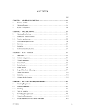
... 3-11 CHAPTER 4 INSTALLATION REQUIREMENTS 4-1 4.1 Mounting Requirements ...4-1 4.1.1 External dimensions ...4-1 4.1.2 Mounting ...4-4 4.1.3 Notes on mounting ...4-4 4.2 Power Supply Requirements 4-8 4.3 Connection Requirements 4-11 4.3.1 68 pin connector 16-bit SCSI model (NP model 4-11 C141-E166 ix
... 3-11 CHAPTER 4 INSTALLATION REQUIREMENTS 4-1 4.1 Mounting Requirements ...4-1 4.1.1 External dimensions ...4-1 4.1.2 Mounting ...4-4 4.1.3 Notes on mounting ...4-4 4.2 Power Supply Requirements 4-8 4.3 Connection Requirements 4-11 4.3.1 68 pin connector 16-bit SCSI model (NP model 4-11 C141-E166 ix
Manual/User Guide
Page 12
... SCSI model (NC model 4-19 Cable connector requirements 4-20 External operator panel (on NP model drives only 4-22 CHAPTER 5 INSTALLATION 5-1 5.1 Notes on Handling Drives 5-1 5.2 Connections...5-3 5.3 Setting Terminals ...5-5 5.3.1 SCSI ID setting (NP model only 5-6 5.3.2 Each mode setting (NP model only 5-7 5.3.3 Mode settings ...5-9 5.4 Mounting Drives...5-10 5.4.1 Check before mounting ...5-10 5.4.2 Mounting procedures...5-10 5.5 Connecting Cables...5-11 5.6 Confirming Operations...
... SCSI model (NC model 4-19 Cable connector requirements 4-20 External operator panel (on NP model drives only 4-22 CHAPTER 5 INSTALLATION 5-1 5.1 Notes on Handling Drives 5-1 5.2 Connections...5-3 5.3 Setting Terminals ...5-5 5.3.1 SCSI ID setting (NP model only 5-6 5.3.2 Each mode setting (NP model only 5-7 5.3.3 Mode settings ...5-9 5.4 Mounting Drives...5-10 5.4.1 Check before mounting ...5-10 5.4.2 Mounting procedures...5-10 5.5 Connecting Cables...5-11 5.6 Confirming Operations...
Manual/User Guide
Page 13
...6.4.2 6.4.3 6.4.4 6.4.5 Diagnostic test ...6-12 Troubleshooting Procedures 6-13 Outline of troubleshooting procedures 6-13 Troubleshooting with disk drive replacement in the field 6-13 Troubleshooting at the repair site 6-15 Troubleshooting with parts replacement in the factory ...-00), (B-47-xx), (B-49-00), (B-4D-xx) and (B-4E-00): SCSI interface error 7-4 APPENDIX A SETTING TERMINALS A-1 A.1 Setting Terminals (on NP model only A-2 APPENDIX B CONNECTOR SIGNAL ALLOCATION B-1 B.1 SCSI Connector Signal Allocation: 68 pin type LVD 16-bit SCSI B-2 B.2 SCSI Connector Signal Allocation: ...
...6.4.2 6.4.3 6.4.4 6.4.5 Diagnostic test ...6-12 Troubleshooting Procedures 6-13 Outline of troubleshooting procedures 6-13 Troubleshooting with disk drive replacement in the field 6-13 Troubleshooting at the repair site 6-15 Troubleshooting with parts replacement in the factory ...-00), (B-47-xx), (B-49-00), (B-4D-xx) and (B-4E-00): SCSI interface error 7-4 APPENDIX A SETTING TERMINALS A-1 A.1 Setting Terminals (on NP model only A-2 APPENDIX B CONNECTOR SIGNAL ALLOCATION B-1 B.1 SCSI Connector Signal Allocation: 68 pin type LVD 16-bit SCSI B-2 B.2 SCSI Connector Signal Allocation: ...
Manual/User Guide
Page 15
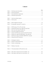
FIGURES Figure 1.1 Figure 1.2 Figure 1.3 Figure 1.4 page NC model drives outer view 1-6 NP model drives outer view 1-6 Disk/head configuration...1-7 System configuration ...1-9 Figure 3.1 Figure 3.2 Figure 3.3 Figure 3.4 Figure 3.5 Figure 3.6 Figure 3.7 Figure... 4.11 Figure 4.12 Figure 4.13 Figure 4.14 Figure 4.15 Figure 4.16 Figure 4.17 Figure 4.18 Figure 4.19 NC external dimensions...4-2 NP external dimensions ...4-3 IDD orientations ...4-4 Mounting frame structure ...4-5 Limitation of side-mounting 4-5 Surface temperature measurement points 4-6 Service clearance area ...4-7 Current ...
FIGURES Figure 1.1 Figure 1.2 Figure 1.3 Figure 1.4 page NC model drives outer view 1-6 NP model drives outer view 1-6 Disk/head configuration...1-7 System configuration ...1-9 Figure 3.1 Figure 3.2 Figure 3.3 Figure 3.4 Figure 3.5 Figure 3.6 Figure 3.7 Figure... 4.11 Figure 4.12 Figure 4.13 Figure 4.14 Figure 4.15 Figure 4.16 Figure 4.17 Figure 4.18 Figure 4.19 NC external dimensions...4-2 NP external dimensions ...4-3 IDD orientations ...4-4 Mounting frame structure ...4-5 Limitation of side-mounting 4-5 Surface temperature measurement points 4-6 Service clearance area ...4-7 Current ...
Manual/User Guide
Page 16
... type SCSI connector 4-20 External operator panel circuit example 4-22 Figure 5.1 Figure 5.2 Figure 5.3 Figure 5.4 Figure 5.5 SCSI bus connections ...5-4 Setting terminals location (on NP models only 5-5 CN2 setting terminal (on NP models only 5-6 Checking the SCSI connection (A 5-14 Checking the SCSI connection (B 5-15 Figure 6.1 Figure 6.2 Figure 6.3 Revision label ...6-9 Indicating revision numbers 6-10 Test...
... type SCSI connector 4-20 External operator panel circuit example 4-22 Figure 5.1 Figure 5.2 Figure 5.3 Figure 5.4 Figure 5.5 SCSI bus connections ...5-4 Setting terminals location (on NP models only 5-5 CN2 setting terminal (on NP models only 5-6 Checking the SCSI connection (A 5-14 Checking the SCSI connection (B 5-15 Figure 6.1 Figure 6.2 Figure 6.3 Revision label ...6-9 Indicating revision numbers 6-10 Test...
Manual/User Guide
Page 17
... only 5-10 Table 6.1 Self-diagnostic functions ...6-1 Table 6.2 System-level field troubleshooting 6-14 Table 6.3 Disk drive troubleshooting ...6-15 Table 7.1 Definition of sense data ...7-3 Table A.1 CN2 setting terminal (on NP model drives only A-2 Table B.1 SCSI connector (68 pin type LVD 16-bit SCSI): CN1 B-2 Table B.2 SCSI connector (SCA2 type LVD 16-bit SCSI): CN1 B-3 C141...
... only 5-10 Table 6.1 Self-diagnostic functions ...6-1 Table 6.2 System-level field troubleshooting 6-14 Table 6.3 Disk drive troubleshooting ...6-15 Table 7.1 Definition of sense data ...7-3 Table A.1 CN2 setting terminal (on NP model drives only A-2 Table B.1 SCSI connector (68 pin type LVD 16-bit SCSI): CN1 B-2 Table B.2 SCSI connector (SCA2 type LVD 16-bit SCSI): CN1 B-3 C141...
Manual/User Guide
Page 20
... ultra SCSI model, number of connectable SCSI devices on the same SCSI bus is varied as follows. • 8-bit SCSI: 8 drives max. (option for NP model) • 16-bit SCSI: 16 drives max. (4) High speed data transfer Such a high data transfer rate on the SCSI bus is 320 MB/s maximum at the paced...-bit SCSI: The data transfer rate on the SCSI bus can manipulate data through logical block addressing regardless of the physical characteristics of the disk drive. The IDD can be useful with the large capacity buffer in the standard 3.5 type fixed disk...
... ultra SCSI model, number of connectable SCSI devices on the same SCSI bus is varied as follows. • 8-bit SCSI: 8 drives max. (option for NP model) • 16-bit SCSI: 16 drives max. (4) High speed data transfer Such a high data transfer rate on the SCSI bus is 320 MB/s maximum at the paced...-bit SCSI: The data transfer rate on the SCSI bus can manipulate data through logical block addressing regardless of the physical characteristics of the disk drive. The IDD can be useful with the large capacity buffer in the standard 3.5 type fixed disk...
Manual/User Guide
Page 24
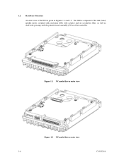
The IDD is given in Figures 1.1 and 1.2. 1.2 Hardware Structure An outer view of the IDD is composed of the disk, head, spindle motor, mounted disk enclosure (DE) with actuator and air circulation filter, as well as read/write pre-amp with the printed circuit assembly (PCA) of the controller. Figure 1.1 NC model drives outer view Figure 1.2 NP model drives outer view 1-6 C141-E166
The IDD is given in Figures 1.1 and 1.2. 1.2 Hardware Structure An outer view of the IDD is composed of the disk, head, spindle motor, mounted disk enclosure (DE) with actuator and air circulation filter, as well as read/write pre-amp with the printed circuit assembly (PCA) of the controller. Figure 1.1 NC model drives outer view Figure 1.2 NP model drives outer view 1-6 C141-E166
Manual/User Guide
Page 25
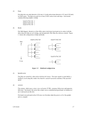
... the disks when the disks are rotated by a feedback circuit using the counter electromotive current to precisely maintain of disks and heads Base Cover MAP3147NC/NP 0 1 2 3 4 5 6 7 MAP3735NC/NP 0 1 2 3 MAP3367NC/NP 0 1 Figure 1.3 Disk/head configuration (3) Spindle motor The disks are not rotating, and automatically float when the rotation is stopped. Resistive) of the CSS (contact... heads are good for MAP series. C141-E166 1-7 The motor speed is controlled and positioned via feedback of the actuator arm is controlled by a direct-drive hall-less DC motor.
... the disks when the disks are rotated by a feedback circuit using the counter electromotive current to precisely maintain of disks and heads Base Cover MAP3147NC/NP 0 1 2 3 4 5 6 7 MAP3735NC/NP 0 1 2 3 MAP3367NC/NP 0 1 Figure 1.3 Disk/head configuration (3) Spindle motor The disks are not rotating, and automatically float when the rotation is stopped. Resistive) of the CSS (contact... heads are good for MAP series. C141-E166 1-7 The motor speed is controlled and positioned via feedback of the actuator arm is controlled by a direct-drive hall-less DC motor.
Manual/User Guide
Page 28
...devices. (2) Addressing of SCSI ID and LUN are as follows: • SCSI ID: • LUN: 8-bit SCSI:Selectable from 0 to 7 (option for NP model, switch selectable) 16-bit SCSI:Selectable from 0 to select the peripheral device for input/output operation. A unique address (LUN: logical unit number) is ...on the bus has its own unique address (SCSI ID:#n in Figure 1.4). The IDD is constructed so that the whole volume of disk drive is a single logical unit, the selectable number of peripheral device Each SCSI device on which multiple host computers that operate as initiator or ...
...devices. (2) Addressing of SCSI ID and LUN are as follows: • SCSI ID: • LUN: 8-bit SCSI:Selectable from 0 to 7 (option for NP model, switch selectable) 16-bit SCSI:Selectable from 0 to select the peripheral device for input/output operation. A unique address (LUN: logical unit number) is ...on the bus has its own unique address (SCSI ID:#n in Figure 1.4). The IDD is constructed so that the whole volume of disk drive is a single logical unit, the selectable number of peripheral device Each SCSI device on which multiple host computers that operate as initiator or ...
Manual/User Guide
Page 30
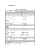
.... (60 s max.) 30 s typ. 32/34 MEEPRML 25.4 mm 101.6 mm 146.0 mm 0.75 kg 9.6 W Cable length: 6 m max MAP3367NC/NP 36.74 GB 1 2 48,104 Single- Table 2.2 Function specifications Item Formatted capacity/device (*1) Number of disks Number of heads Number of cylinders (*2) Formatted capacity/track (B)... max (*6) Cable length: 1.5 m max (*7) LVD U160 Cable length: 25 m max (*8) Cable length: 12 m max (*9) Data transfer rate (*10) Disk drive SCSI Synchronous mode 64.1 to 528 byte (Fixed length) SCSI command specification SPI-4 (T10/1365D Rev.7), SAM-2 (T10/1157D Rev.20), SPC-2 (T10/1236D ...
.... (60 s max.) 30 s typ. 32/34 MEEPRML 25.4 mm 101.6 mm 146.0 mm 0.75 kg 9.6 W Cable length: 6 m max MAP3367NC/NP 36.74 GB 1 2 48,104 Single- Table 2.2 Function specifications Item Formatted capacity/device (*1) Number of disks Number of heads Number of cylinders (*2) Formatted capacity/track (B)... max (*6) Cable length: 1.5 m max (*7) LVD U160 Cable length: 25 m max (*8) Cable length: 12 m max (*9) Data transfer rate (*10) Disk drive SCSI Synchronous mode 64.1 to 528 byte (Fixed length) SCSI command specification SPI-4 (T10/1365D Rev.7), SAM-2 (T10/1157D Rev.20), SPC-2 (T10/1236D ...
Manual/User Guide
Page 32
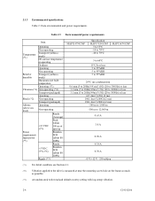
... Input power (about 80 (*5) IOPS) Ready +5 VDC ±5% (*6) Random W/R (about 80 IOPS) Ripple (*7) MAP3147NC/NP Specification MAP3735NC/NP 5 to 55°C -10 to 70°C -40 to 70°C MAP3367NC/NP 5 to 60°C 15°C/h or less 5 to 95%RH 5 to 95%RH 5 to 95%RH 29°... to 3,000 m -300 m to 12,000 m 0.63 A 3.0 A 0.90 A 0.38 A 0.70 A +5 V/+12 V 250 mVp-p (*1) For detail condition, see Section 4.1. (*2) Vibration applied to the drive is measured at near the mounting screw hole on the frame as much as possible. (*3) At random seek write/read and default on retry setting...
... Input power (about 80 (*5) IOPS) Ready +5 VDC ±5% (*6) Random W/R (about 80 IOPS) Ripple (*7) MAP3147NC/NP Specification MAP3735NC/NP 5 to 55°C -10 to 70°C -40 to 70°C MAP3367NC/NP 5 to 60°C 15°C/h or less 5 to 95%RH 5 to 95%RH 5 to 95%RH 29°... to 3,000 m -300 m to 12,000 m 0.63 A 3.0 A 0.90 A 0.38 A 0.70 A +5 V/+12 V 250 mVp-p (*1) For detail condition, see Section 4.1. (*2) Vibration applied to the drive is measured at near the mounting screw hole on the frame as much as possible. (*3) At random seek write/read and default on retry setting...
Manual/User Guide
Page 35
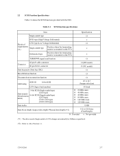
... the terminating resistor is mounted on the PCA × TERMPWR signal send function Ο Connector 68 pin P cable connector 80 pin SCA2 connector Ο (NP model) Ο (NC model) Data bus parity (Data bus CRC) Ο Bus arbitration function Ο Disconnection/reconnection function Ο Addressing SCSI ID 16-bit SCSI...
... the terminating resistor is mounted on the PCA × TERMPWR signal send function Ο Connector 68 pin P cable connector 80 pin SCA2 connector Ο (NP model) Ο (NC model) Data bus parity (Data bus CRC) Ο Bus arbitration function Ο Disconnection/reconnection function Ο Addressing SCSI ID 16-bit SCSI...

Manual/User Guide
Page 38
... space (Primary Cylinder 0 - (n - 1)) User Space for Cell P1-0 Spare Sectors per Cell P1 Alternate Cylinder User Space for Cell yy-17 n = MAP3147NC/NP: 47,589 MAP3735NC/NP: 47,645 MAP3367NC/NP: 47,771 Note: Spare sectors on the last track in each cylinder are not necessarily placed at the end of the track because...
... space (Primary Cylinder 0 - (n - 1)) User Space for Cell P1-0 Spare Sectors per Cell P1 Alternate Cylinder User Space for Cell yy-17 n = MAP3147NC/NP: 47,589 MAP3735NC/NP: 47,645 MAP3367NC/NP: 47,771 Note: Spare sectors on the last track in each cylinder are not necessarily placed at the end of the track because...
Manual/User Guide
Page 39
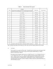
... also specify the number of data blocks) can be placed in the user space. C141-E166 3-3 Table 3.1 Zone layout and track capacity Zone Cylinder MAP3147NC/NP MAP3735NC/NP MAP3367NC/NP Byte/track Sector/track 0 0 - 1,120 479,232 936 1 1,121 - 4,117 465,920 910 2 4,118 - 6,078 459,264 897 3 6,079 - ... User space The user space is a storage area for each series. The default value of logical data blocks is MAP3174NC/NP = 47,589, MAP3735NC/NP = 47,645, MAP3367NC/NP = 47,771. These also equal the maximum cylinders number for user data. The data format on the user space (...
... also specify the number of data blocks) can be placed in the user space. C141-E166 3-3 Table 3.1 Zone layout and track capacity Zone Cylinder MAP3147NC/NP MAP3735NC/NP MAP3367NC/NP Byte/track Sector/track 0 0 - 1,120 479,232 936 1 1,121 - 4,117 465,920 910 2 4,118 - 6,078 459,264 897 3 6,079 - ... User space The user space is a storage area for each series. The default value of logical data blocks is MAP3174NC/NP = 47,589, MAP3735NC/NP = 47,645, MAP3367NC/NP = 47,771. These also equal the maximum cylinders number for user data. The data format on the user space (...
Manual/User Guide
Page 45
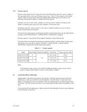
... The IDD relates a logical data block address to each drive. Table 3.4 Format capacity Model Data heads Data block length MAP3147NC/NP 8 MAP3735NC/NP 4 512 MAP3367NC/NP 2 User blocks 287,132,440 143,571,316 71,775,284 Format capacity (GB) 147.01 73.50 36.74 Note: Total number of spare sectors is a function ...and the default spare area are used when the number of logical data blocks are given addresses of that data. number of the disk drive, the IDD adopts the logical data block addressing as a data access method on the disk medium is the general formula to calculate ...
... The IDD relates a logical data block address to each drive. Table 3.4 Format capacity Model Data heads Data block length MAP3147NC/NP 8 MAP3735NC/NP 4 512 MAP3367NC/NP 2 User blocks 287,132,440 143,571,316 71,775,284 Format capacity (GB) 147.01 73.50 36.74 Note: Total number of spare sectors is a function ...and the default spare area are used when the number of logical data blocks are given addresses of that data. number of the disk drive, the IDD adopts the logical data block addressing as a data access method on the disk medium is the general formula to calculate ...

Manual/User Guide
Page 55
The value marked with (*) indicates the dimension between mounting holes on the bottom face. Figure 4.2 NP external dimensions C141-E166 4-3
The value marked with (*) indicates the dimension between mounting holes on the bottom face. Figure 4.2 NP external dimensions C141-E166 4-3