
Manual/User Guide
Page 4
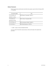
ii C141-E166 Related Standards Product specifications and functions described in this manual takes precedence. Document number T10/1236D Rev.20 [NCITS.351:2001] T10/996D Rev.8c [NCITS.306:1998] T10/1157D Rev.20 T10/1365D Rev.7 Title SCSI Primary Commands-2 (SPC-2) SCSI-3 Block Commands (SBC) SCSI Architecture Model-2 (SAM-2) SCSI Parallel Interface-4 (SPI-4) *1 ANSI = American National Standard Institute In case of conflict between this manual and any referenced document, this manual comply with the following ANSI (*1) standards.
ii C141-E166 Related Standards Product specifications and functions described in this manual takes precedence. Document number T10/1236D Rev.20 [NCITS.351:2001] T10/996D Rev.8c [NCITS.306:1998] T10/1157D Rev.20 T10/1365D Rev.7 Title SCSI Primary Commands-2 (SPC-2) SCSI-3 Block Commands (SBC) SCSI Architecture Model-2 (SAM-2) SCSI Parallel Interface-4 (SPI-4) *1 ANSI = American National Standard Institute In case of conflict between this manual and any referenced document, this manual comply with the following ANSI (*1) standards.
Manual/User Guide
Page 5
...drive, connecting the cables, and confirming drive operation. Chapter 3 DATA FORMAT This chapter describes the data structure of MAP series disk drive. It includes the notice and procedures for installing MAP series disk drives... and the signal assignments of fixed disk drives and their use the other manuals. Chapter.../NP and MAP3367NC/NP (hereafter, MAP series), 3.5 type fixed disk drives with an ... drives. OVERVIEW OF MANUAL This manual consists of the MAP series disk drives ...drives and discusses their installation environment. APPENDIX A to install MAP series disk drives...
...drive, connecting the cables, and confirming drive operation. Chapter 3 DATA FORMAT This chapter describes the data structure of MAP series disk drive. It includes the notice and procedures for installing MAP series disk drives... and the signal assignments of fixed disk drives and their use the other manuals. Chapter.../NP and MAP3367NC/NP (hereafter, MAP series), 3.5 type fixed disk drives with an ... drives. OVERVIEW OF MANUAL This manual consists of the MAP series disk drives ...drives and discusses their installation environment. APPENDIX A to install MAP series disk drives...
Manual/User Guide
Page 13
... 6.4.2 6.4.3 6.4.4 6.4.5 Diagnostic test ...6-12 Troubleshooting Procedures 6-13 Outline of troubleshooting procedures 6-13 Troubleshooting with disk drive replacement in the field 6-13 Troubleshooting at the repair site 6-15 Troubleshooting with parts replacement in the factory 6-... read error 7-4 7.2.4 Sense data (5-2x-xx), (5-3D-00), (5-90-00), (B-47-xx), (B-49-00), (B-4D-xx) and (B-4E-00): SCSI interface error 7-4 APPENDIX A SETTING TERMINALS A-1 A.1 Setting Terminals (on NP model only A-2 APPENDIX B CONNECTOR SIGNAL ALLOCATION B-1 B.1 SCSI Connector Signal Allocation: 68 pin ...
... 6.4.2 6.4.3 6.4.4 6.4.5 Diagnostic test ...6-12 Troubleshooting Procedures 6-13 Outline of troubleshooting procedures 6-13 Troubleshooting with disk drive replacement in the field 6-13 Troubleshooting at the repair site 6-15 Troubleshooting with parts replacement in the factory 6-... read error 7-4 7.2.4 Sense data (5-2x-xx), (5-3D-00), (5-90-00), (B-47-xx), (B-49-00), (B-4D-xx) and (B-4E-00): SCSI interface error 7-4 APPENDIX A SETTING TERMINALS A-1 A.1 Setting Terminals (on NP model only A-2 APPENDIX B CONNECTOR SIGNAL ALLOCATION B-1 B.1 SCSI Connector Signal Allocation: 68 pin ...
Manual/User Guide
Page 15
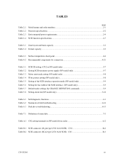
FIGURES Figure 1.1 Figure 1.2 Figure 1.3 Figure 1.4 page NC model drives outer view 1-6 NP model drives outer view 1-6 Disk/head configuration...1-7 System configuration ...1-9 Figure 3.1 Figure 3.2 Figure 3.3 Figure 3.4 Figure 3.5 Figure 3.6 Figure 3.7 Figure 3.8 Cylinder configuration... sequence (2) ...4-9 Power on/off sequence (3) ...4-9 AC noise filter (recommended 4-11 NP connectors and terminals location 4-11 16-bit SCSI interface connector 4-12 Power supply connector (16-bit SCSI model 4-12 External operator panel connector (CN1 4-13 External operator panel connector (CN2 4-...
FIGURES Figure 1.1 Figure 1.2 Figure 1.3 Figure 1.4 page NC model drives outer view 1-6 NP model drives outer view 1-6 Disk/head configuration...1-7 System configuration ...1-9 Figure 3.1 Figure 3.2 Figure 3.3 Figure 3.4 Figure 3.5 Figure 3.6 Figure 3.7 Figure 3.8 Cylinder configuration... sequence (2) ...4-9 Power on/off sequence (3) ...4-9 AC noise filter (recommended 4-11 NP connectors and terminals location 4-11 16-bit SCSI interface connector 4-12 Power supply connector (16-bit SCSI model 4-12 External operator panel connector (CN1 4-13 External operator panel connector (CN2 4-...
Manual/User Guide
Page 17
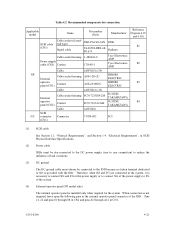
...5-8 Table 5.4 Write protect setting (NP model only 5-8 Table 5.5 Setting of the SCSI interface operation mode (NP model only 5-9 Table 5.6 Setting the bus width of the SCSI interface (NP model only 5-9 Table 5.7 Default mode settings (by CHANGE DEFINITION command 5-9 Table 5.8... Setting check list (NP model only 5-10 Table 6.1 Self-diagnostic functions ...6-1 Table 6.2 System-level field troubleshooting 6-14 Table 6.3 Disk drive troubleshooting ...6-15 Table 7.1 ...
...5-8 Table 5.4 Write protect setting (NP model only 5-8 Table 5.5 Setting of the SCSI interface operation mode (NP model only 5-9 Table 5.6 Setting the bus width of the SCSI interface (NP model only 5-9 Table 5.7 Default mode settings (by CHANGE DEFINITION command 5-9 Table 5.8... Setting check list (NP model only 5-10 Table 6.1 Self-diagnostic functions ...6-1 Table 6.2 System-level field troubleshooting 6-14 Table 6.3 Disk drive troubleshooting ...6-15 Table 7.1 ...
Manual/User Guide
Page 19
IDDs are high performance large capacity 3.5 type fixed disk drives with the user's system. The MAP series disk drives support the Small Computer System Interface (SCSI) as the powerful command set of the IDD, allow the user to construct a high-performance reliable disk subsystem with large storage capacity. The data ... the SCSI, as well as described in the ANSI SCSI SPI-4 [T10/1365D Rev.7] to the extent described in this manual. Refer to SCSI Logical Interface Specifications for details. C141-E166 1-1 The flexibility and expandability of the MAP series intelligent disk...
IDDs are high performance large capacity 3.5 type fixed disk drives with the user's system. The MAP series disk drives support the Small Computer System Interface (SCSI) as the powerful command set of the IDD, allow the user to construct a high-performance reliable disk subsystem with large storage capacity. The data ... the SCSI, as well as described in the ANSI SCSI SPI-4 [T10/1365D Rev.7] to the extent described in this manual. Refer to SCSI Logical Interface Specifications for details. C141-E166 1-1 The flexibility and expandability of the MAP series intelligent disk...
Manual/User Guide
Page 29
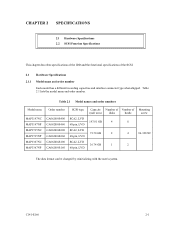
...name and order number. C141-E166 2-1 Table 2.1 Model names and order numbers Model name MAP3147NC MAP3147NP MAP3735NC MAP3735NP MAP3367NC MAP3367NP Order number CA06200-B400 CA06200-B460 CA06200-B200 CA06200-B260 CA06200-B100 CA06200-B160 SCSI type SCA2, LVD 68... Number of Number of the SCSI. 2.1 Hardware Specifications 2.1.1 Model name and order number Each model has a different recording capacities and interface connector type when shipped. CHAPTER 2 SPECIFICATIONS 2.1 Hardware Specifications 2.2 SCSI Function Specifications This chapter describes specifications of the IDD and the ...
...name and order number. C141-E166 2-1 Table 2.1 Model names and order numbers Model name MAP3147NC MAP3147NP MAP3735NC MAP3735NP MAP3367NC MAP3367NP Order number CA06200-B400 CA06200-B460 CA06200-B200 CA06200-B260 CA06200-B100 CA06200-B160 SCSI type SCA2, LVD 68... Number of Number of the SCSI. 2.1 Hardware Specifications 2.1.1 Model name and order number Each model has a different recording capacities and interface connector type when shipped. CHAPTER 2 SPECIFICATIONS 2.1 Hardware Specifications 2.2 SCSI Function Specifications This chapter describes specifications of the IDD and the ...
Manual/User Guide
Page 62
...-second intervals to start the spindle motors. Regarding how to the terminating resistor is selected with considering of an increase of up to SCSI Logical Interface Specifications. a) Issue START/STOP commands at more than one of the following time. [Delay time] = [SCSI ID] × 12 seconds... AC input terminal on the IDD power supply unit. For the NP model drives, the spindle motors should be installed at 10 MHz • Circuit construction: T-configuration as shown in SCSI Physical Interface Specifications. (6) Noise filter To eliminate AC line noise, a noise filter should...
...-second intervals to start the spindle motors. Regarding how to the terminating resistor is selected with considering of an increase of up to SCSI Logical Interface Specifications. a) Issue START/STOP commands at more than one of the following time. [Delay time] = [SCSI ID] × 12 seconds... AC input terminal on the IDD power supply unit. For the NP model drives, the spindle motors should be installed at 10 MHz • Circuit construction: T-configuration as shown in SCSI Physical Interface Specifications. (6) Noise filter To eliminate AC line noise, a noise filter should...
Manual/User Guide
Page 64
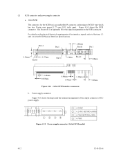
...Pin A1 Pin 1 2.54mm Pin 68 1.27mm Pin 35 2.00m Pin A2 5.08mm 0.40mm 0.635mm 0.40mm 1.00mm 1.30mm Figure 4.14 16-bit SCSI interface connector 5.08mm b. Figure 4.14 shows the SCSI connector. (2) SCSI connector and power supply connector a. 16-bit SCSI The connector for the signal assignments on.../electrical requirements of DC power supply. Power supply connector Figure 4.15 shows the shape and the terminal arrangement of the output connector of the interface signals, refer to SCSI-3 type which has two 34-pin rows spaced 1.27 mm (0.05 inch) apart. See Section B.1 in Appendix ...
...Pin A1 Pin 1 2.54mm Pin 68 1.27mm Pin 35 2.00m Pin A2 5.08mm 0.40mm 0.635mm 0.40mm 1.00mm 1.30mm Figure 4.14 16-bit SCSI interface connector 5.08mm b. Figure 4.14 shows the SCSI connector. (2) SCSI connector and power supply connector a. 16-bit SCSI The connector for the signal assignments on.../electrical requirements of DC power supply. Power supply connector Figure 4.15 shows the shape and the terminal arrangement of the output connector of the interface signals, refer to SCSI-3 type which has two 34-pin rows spaced 1.27 mm (0.05 inch) apart. See Section B.1 in Appendix ...
Manual/User Guide
Page 71
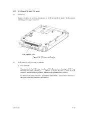
4.3.2 SCA2 type SCSI model (NC model) (1) Connectors Figure 4.21 shows the locations of the interface signals, refer to SCSI-3 type which has two 40-pin rows spaced 1.27 mm (0.05 inch) apart. C141-E166 4-19 See Section B.2 in Appendix B for ...the SCSI bus is an unshielded SCA-2 connector conforming to Sections 1.3 and 1.4 in SCSI Physical Interface Specifications. SCA type SCSI The connector for signal assignments on the SCA2 type SCSI model. Figure 4.22 shows the SCSI connector. SCSI connector (including power...
4.3.2 SCA2 type SCSI model (NC model) (1) Connectors Figure 4.21 shows the locations of the interface signals, refer to SCSI-3 type which has two 40-pin rows spaced 1.27 mm (0.05 inch) apart. C141-E166 4-19 See Section B.2 in Appendix B for ...the SCSI bus is an unshielded SCA-2 connector conforming to Sections 1.3 and 1.4 in SCSI Physical Interface Specifications. SCA type SCSI The connector for signal assignments on the SCA2 type SCSI model. Figure 4.22 shows the SCSI connector. SCSI connector (including power...
Manual/User Guide
Page 73
... 01 through 08 in CN2 and pins A1 through A12 in SCSI Physical Interface Specifications. (2) Power cable IDDs must be star-connected to the DC power supply (one to one connection) to 36) FCN-723J024/2M FUJITSU TAKAMIZAWA FCN-723J-G/AM FUJITSU TAKAMIZAWA (AWG28) 71780-003 FCI Reference (Figures 4.25 and 4.30) S1 S2...
... 01 through 08 in CN2 and pins A1 through A12 in SCSI Physical Interface Specifications. (2) Power cable IDDs must be star-connected to the DC power supply (one to one connection) to 36) FCN-723J024/2M FUJITSU TAKAMIZAWA FCN-723J-G/AM FUJITSU TAKAMIZAWA (AWG28) 71780-003 FCI Reference (Figures 4.25 and 4.30) S1 S2...
Manual/User Guide
Page 76
... c) Indicate "This Side Up" and "Handle With Care" on hard material such as those at delivery cannot be altered are not damaged. The only pin settings that it is not turned over. (5) Delivery a) When delivering the drive, provide packaging and do not turn it over. c) To prevent...get lost or damaged. For the carrying direction at delivery. c) Be careful not to give excess pressure to the PCAs and interface connector when removing the drive from direct shocks. d) Do not remove the sealing label or cover of the mount allowable directions in Subsection 4.2.2 (vertical ...
... c) Indicate "This Side Up" and "Handle With Care" on hard material such as those at delivery cannot be altered are not damaged. The only pin settings that it is not turned over. (5) Delivery a) When delivering the drive, provide packaging and do not turn it over. c) To prevent...get lost or damaged. For the carrying direction at delivery. c) Be careful not to give excess pressure to the PCAs and interface connector when removing the drive from direct shocks. d) Do not remove the sealing label or cover of the mount allowable directions in Subsection 4.2.2 (vertical ...
Manual/User Guide
Page 82
...microcode is downloaded. When this setup terminal is open, the IDD automatically identifies the DIFFSNS signal level on the SCSI bus and the IDD SCSI interface operation mode is forcibly set to Table 5.3. CN2 9-10 Open Short (default) (4) Setting of the START/STOP UNIT command. (3) Write ...NP model only) Write protect Write operation is disabled. CN2 11-12 Open Short (default) Refer to Chapter 3 of the SCSI Logical Interface Specifications for details of the SCSI interface operation mode By establishing a short-circuit between the 15 and 16 CN2 setting terminals, the SCSI...
...microcode is downloaded. When this setup terminal is open, the IDD automatically identifies the DIFFSNS signal level on the SCSI bus and the IDD SCSI interface operation mode is forcibly set to Table 5.3. CN2 9-10 Open Short (default) (4) Setting of the START/STOP UNIT command. (3) Write ...NP model only) Write protect Write operation is disabled. CN2 11-12 Open Short (default) Refer to Chapter 3 of the SCSI Logical Interface Specifications for details of the SCSI interface operation mode By establishing a short-circuit between the 15 and 16 CN2 setting terminals, the SCSI...
Manual/User Guide
Page 83
...settings using setting terminals, the IDD is not connected to Section 3.1.4 of the SCSI Logical Interface Specifications for the IDD SCSI interface is provided with several mode settings. Table 5.6 Setting the bus width of the SCSI interface (NP model only) Bus width 16 bit bus 8 bit bus CN2 13-14 Open ...Short (default) 5.3.3 Mode settings In addition to the 8-bit bus mode. Table 5.5 Setting of the SCSI interface operation mode (NP model only) Operation mode Follows the DIFFSNS signal level on the SCSI bus Single-Ended mode CN2 15-16 Open Short (default...
...settings using setting terminals, the IDD is not connected to Section 3.1.4 of the SCSI Logical Interface Specifications for the IDD SCSI interface is provided with several mode settings. Table 5.6 Setting the bus width of the SCSI interface (NP model only) Bus width 16 bit bus 8 bit bus CN2 13-14 Open ...Short (default) 5.3.3 Mode settings In addition to the 8-bit bus mode. Table 5.5 Setting of the SCSI interface operation mode (NP model only) Operation mode Follows the DIFFSNS signal level on the SCSI bus Single-Ended mode CN2 15-16 Open Short (default...
Manual/User Guide
Page 90
...byte length) of the logical data block in "number of the motor start mode and UNIT ATTENTION report mode. 5.6.3 Formatting Since the disk drive is connected to Chapter 5 of data blocks" field. Otherwise, specify 0 in the "data block length" field. (2) Checking at abnormal... recovery for further details. To explicitly specify the number of logical data blocks, specify the number in the "number of SCSI Logical Interface Specifications for a recoverable error. Refer to the terminating resistor. b) Check the following data attributes at initialization: • Logical data...
...byte length) of the logical data block in "number of the motor start mode and UNIT ATTENTION report mode. 5.6.3 Formatting Since the disk drive is connected to Chapter 5 of data blocks" field. Otherwise, specify 0 in the "data block length" field. (2) Checking at abnormal... recovery for further details. To explicitly specify the number of logical data blocks, specify the number in the "number of SCSI Logical Interface Specifications for a recoverable error. Refer to the terminating resistor. b) Check the following data attributes at initialization: • Logical data...

Manual/User Guide
Page 92
... the initialization of the disk is performed by the FORMAT UNIT command, the saved value of the system requirements specific to Chapter 3 of SCSI Logical Interface Specifications for further details of the IDD, the saving operation for the MODE SELECT parameter is not executed at installation. 5-18 C141-E166 When the...
... the initialization of the disk is performed by the FORMAT UNIT command, the saved value of the system requirements specific to Chapter 3 of SCSI Logical Interface Specifications for further details of the IDD, the saving operation for the MODE SELECT parameter is not executed at installation. 5-18 C141-E166 When the...
Manual/User Guide
Page 94
...command) or write operation (WRITE, WRITE EXTENDED, or WRITE AND VERIFY command) of the disk. Refer to Chapter 2 of SCSI Logical Interface Specifications for how to be specified. 2. The user also can arbitrarily specify the following performance factors of the system: • Time required... transfer rate of the SCSI bus • Average amount of processing data specified with a command Refer to Chapter 2 of SCSI Logical Interface Specifications for the parameter values to obtain the rough calculation values for further details. • Buffer full ratio • Buffer empty ratio...
...command) or write operation (WRITE, WRITE EXTENDED, or WRITE AND VERIFY command) of the disk. Refer to Chapter 2 of SCSI Logical Interface Specifications for how to be specified. 2. The user also can arbitrarily specify the following performance factors of the system: • Time required... transfer rate of the SCSI bus • Average amount of processing data specified with a command Refer to Chapter 2 of SCSI Logical Interface Specifications for the parameter values to obtain the rough calculation values for further details. • Buffer full ratio • Buffer empty ratio...

Manual/User Guide
Page 95
Refer to Chapter 2 of SCSI Logical Interface Specifications for which prefetch is not determined uniquely because of segments Default value 0 (Drive-specific control (page cache)) 0 (enabled) 1 (enabled) 0 (Specifying absolute value) 1 (enable) X'FFFF' X'0000' X' XXXX' (1 cache segment) X'FFFF' X'08' Notes: 1. When the access form is suppressed • ...
Refer to Chapter 2 of SCSI Logical Interface Specifications for which prefetch is not determined uniquely because of segments Default value 0 (Drive-specific control (page cache)) 0 (enabled) 1 (enabled) 0 (Specifying absolute value) 1 (enable) X'FFFF' X'0000' X' XXXX' (1 cache segment) X'FFFF' X'08' Notes: 1. When the access form is suppressed • ...
Manual/User Guide
Page 96
...operator panel is resumed) 0 (enabled) 5.7 Dismounting Drives Since dismounting the drive to make sure the spindle motor completely stops after ...drive, then remove the drive from the system cabinet. a) Remove the power cable. f) To store or transport the drive, keep it is recommended before dismounting the drive... to check the setting terminals, change the setting, or change the drive depends on dismounting the drive... and provide packing (see Section 5.1). 5.8 Spare Disk Drive See 2.1.1, "Model name and order number," to access...
...operator panel is resumed) 0 (enabled) 5.7 Dismounting Drives Since dismounting the drive to make sure the spindle motor completely stops after ...drive, then remove the drive from the system cabinet. a) Remove the power cable. f) To store or transport the drive, keep it is recommended before dismounting the drive... to check the setting terminals, change the setting, or change the drive depends on dismounting the drive... and provide packing (see Section 5.1). 5.8 Spare Disk Drive See 2.1.1, "Model name and order number," to access...

Manual/User Guide
Page 97
... basic operations of the IDD. • Initial self-diagnostics • Online self-diagnostics (SEND DIAGNOSTIC command) Table 6.1 lists the contents of the host system and interface, use a test program that runs on the host system (see Subsection 6.1.2).
... basic operations of the IDD. • Initial self-diagnostics • Online self-diagnostics (SEND DIAGNOSTIC command) Table 6.1 lists the contents of the host system and interface, use a test program that runs on the host system (see Subsection 6.1.2).
