

Manual/User Guide
Page 2
... before using this manual may be disclosed in any way or reproduced in any media without the express written permission of Fujitsu Limited. Read thoroughly before embarking on such specialized use ). The contents of this manual, its updates or supplements, whether such... obligation. Customers considering the use in standard applications such as "mission-critical" use . All Right Reserved, Copyright © FUJITSU LIMITED 2002 C141-E166 FOR SAFE OPERATION Handling of This manual This manual contains important information for mission-critical applications must have safety-...
... before using this manual may be disclosed in any way or reproduced in any media without the express written permission of Fujitsu Limited. Read thoroughly before embarking on such specialized use ). The contents of this manual, its updates or supplements, whether such... obligation. Customers considering the use in standard applications such as "mission-critical" use . All Right Reserved, Copyright © FUJITSU LIMITED 2002 C141-E166 FOR SAFE OPERATION Handling of This manual This manual contains important information for mission-critical applications must have safety-...
Manual/User Guide
Page 15
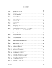
FIGURES Figure 1.1 Figure 1.2 Figure 1.3 Figure 1.4 page NC model drives outer view 1-6 NP model drives outer view 1-6 Disk/head configuration...1-7 System configuration ...1-9 Figure 3.1 Figure 3.2 Figure 3.3 Figure 3.4 Figure 3.5 Figure 3.6 Figure 3.7 ... Figure 4.16 Figure 4.17 Figure 4.18 Figure 4.19 NC external dimensions...4-2 NP external dimensions ...4-3 IDD orientations ...4-4 Mounting frame structure ...4-5 Limitation of side-mounting 4-5 Surface temperature measurement points 4-6 Service clearance area ...4-7 Current waveform (+12 VDC 4-8 Power on/off sequence (1) ...4-9 Power...
FIGURES Figure 1.1 Figure 1.2 Figure 1.3 Figure 1.4 page NC model drives outer view 1-6 NP model drives outer view 1-6 Disk/head configuration...1-7 System configuration ...1-9 Figure 3.1 Figure 3.2 Figure 3.3 Figure 3.4 Figure 3.5 Figure 3.6 Figure 3.7 ... Figure 4.16 Figure 4.17 Figure 4.18 Figure 4.19 NC external dimensions...4-2 NP external dimensions ...4-3 IDD orientations ...4-4 Mounting frame structure ...4-5 Limitation of side-mounting 4-5 Surface temperature measurement points 4-6 Service clearance area ...4-7 Current waveform (+12 VDC 4-8 Power on/off sequence (1) ...4-9 Power...
Manual/User Guide
Page 21
...actual data transfer rate of SCSI bus length. The maximum data transfer rate in synchronous mode may be limited by the response time of initiator and the length of the disk drive. (7) Cache feature After executing the READ command, the IDD reads automatically and stores (prefetches) the ...This feature realizes the high speed processing. This feature provides the suitable usage environment for users. To ensure it, you turn off the drive's power. The continuous processing up to the data buffer or empty condition of the data buffer, the initiator can perform the effective input...
...actual data transfer rate of SCSI bus length. The maximum data transfer rate in synchronous mode may be limited by the response time of initiator and the length of the disk drive. (7) Cache feature After executing the READ command, the IDD reads automatically and stores (prefetches) the ...This feature realizes the high speed processing. This feature provides the suitable usage environment for users. To ensure it, you turn off the drive's power. The continuous processing up to the data buffer or empty condition of the data buffer, the initiator can perform the effective input...

Manual/User Guide
Page 57
Figure 4.5 Limitation of side-mounting (3) Limitation of bottom-mounting Use all 4 mounting holes on the both ends. (Total 6 screws for 6 holes enclosed) 4 Holes for mounting screw. 1 Use four holes (No.1-4) to .... Do not use these holes Holes for mounting screw. 3 2 Do not use the center hole by itself. 5.0 or less 5.0 or less Figure 4.4 Mounting frame structure (2) Limitation of side-mounting Mount the IDD using the center hole, it must be used in combination with 2 holes on both sides as shown in Figure...
Figure 4.5 Limitation of side-mounting (3) Limitation of bottom-mounting Use all 4 mounting holes on the both ends. (Total 6 screws for 6 holes enclosed) 4 Holes for mounting screw. 1 Use four holes (No.1-4) to .... Do not use these holes Holes for mounting screw. 3 2 Do not use the center hole by itself. 5.0 or less 5.0 or less Figure 4.4 Mounting frame structure (2) Limitation of side-mounting Mount the IDD using the center hole, it must be used in combination with 2 holes on both sides as shown in Figure...

Manual/User Guide
Page 93
... RESET condition, or the BUS DEVICE RESET message. Additional error recovery parameters (page code = 21) Parameter • Retry count at write operation • Recovery time limit Default value 1 (enabled) 1 (enabled) 1 (enabled) 1 (enabled) 0 (disabled) 0 (Correction is enabled.) 63 c. 5.
... RESET condition, or the BUS DEVICE RESET message. Additional error recovery parameters (page code = 21) Parameter • Retry count at write operation • Recovery time limit Default value 1 (enabled) 1 (enabled) 1 (enabled) 1 (enabled) 0 (disabled) 0 (Correction is enabled.) 63 c. 5.
Manual/User Guide
Page 124
... space 3-4 L large capacity 1-5 leak magnetic flux 4-7 limitation of bottom-mounting 4-5 limitation of side-mounting 4-5 logical data block addressing 3-9 low ...noise and low vibration 1-5 low power consumption 1-5 M maintenance level 6-8 maintenance requirement 6-6 mean time between failure (MTBF 2-5 mean time to repair (MTTR 2-6 microcode downloading 1-5 MODE SELECT/MODE SELECT EXTENDED command............5-16 mode setting 5-9 motor start mode 5-8 motor start mode setting 5-8 mounting 4-4 mounting drive...
... space 3-4 L large capacity 1-5 leak magnetic flux 4-7 limitation of bottom-mounting 4-5 limitation of side-mounting 4-5 logical data block addressing 3-9 low ...noise and low vibration 1-5 low power consumption 1-5 M maintenance level 6-8 maintenance requirement 6-6 mean time between failure (MTBF 2-5 mean time to repair (MTTR 2-6 microcode downloading 1-5 MODE SELECT/MODE SELECT EXTENDED command............5-16 mode setting 5-9 motor start mode 5-8 motor start mode setting 5-8 mounting 4-4 mounting drive...

Manual/User Guide
Page 127
...;g 12, S-192 68 Sollentura, SWEDEN TEL: 46-8-626-4500 FAX: 46-8-626-4588 FUJITSU ITALIA S.p.A. Almagro 40, 28010 Madrid, SPAIN TEL: 34-91-581-8000 FAX: 34-91-581-8300 FUJITSU AUSTRALIA LIMITED 2 Julius Avenue (Cnr Delhi Road) North Ryde N.S.W. 2113, AUSTRALIA TEL: 61-2-9776...Place, Island East, Hong Kong TEL: 852-2827-5780 FAX: 852-2827-4724 FUJITSU KOREA LTD. Coryo Finance Center Bldg, 23-6, YoulDo-Dong, Young DungPo-Gu, Seoul, Republic of the following addresses: FUJITSU LIMITED Storage Products Group 4-1-1 Kamikodanaka, Nakahara-ku, Kawasaki, 211-8588, Japan TEL: ...
...;g 12, S-192 68 Sollentura, SWEDEN TEL: 46-8-626-4500 FAX: 46-8-626-4588 FUJITSU ITALIA S.p.A. Almagro 40, 28010 Madrid, SPAIN TEL: 34-91-581-8000 FAX: 34-91-581-8300 FUJITSU AUSTRALIA LIMITED 2 Julius Avenue (Cnr Delhi Road) North Ryde N.S.W. 2113, AUSTRALIA TEL: 61-2-9776...Place, Island East, Hong Kong TEL: 852-2827-5780 FAX: 852-2827-4724 FUJITSU KOREA LTD. Coryo Finance Center Bldg, 23-6, YoulDo-Dong, Young DungPo-Gu, Seoul, Republic of the following addresses: FUJITSU LIMITED Storage Products Group 4-1-1 Kamikodanaka, Nakahara-ku, Kawasaki, 211-8588, Japan TEL: ...

Manual/User Guide
Page 129
FUJITSU LIMITED Reader Comment Form Publication No. Fully covered Well Illustrated What is your overall rating of the addresses in a previous page. Very Poor Your other comments ...
FUJITSU LIMITED Reader Comment Form Publication No. Fully covered Well Illustrated What is your overall rating of the addresses in a previous page. Very Poor Your other comments ...