
Manual/User Guide
Page 4
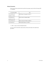
ii C141-E166 Document number T10/1236D Rev.20 [NCITS.351:2001] T10/996D Rev.8c [NCITS.306:1998] T10/1157D Rev.20 T10/1365D Rev.7 Title SCSI Primary Commands-2 (SPC-2) SCSI-3 Block Commands (SBC) SCSI Architecture Model-2 (SAM-2) SCSI Parallel Interface-4 (SPI-4) *1 ANSI = American National Standard Institute In case of conflict between this manual and any referenced document, this manual comply with the following ANSI (*1) standards. Related Standards Product specifications and functions described in this manual takes precedence.
ii C141-E166 Document number T10/1236D Rev.20 [NCITS.351:2001] T10/996D Rev.8c [NCITS.306:1998] T10/1157D Rev.20 T10/1365D Rev.7 Title SCSI Primary Commands-2 (SPC-2) SCSI-3 Block Commands (SBC) SCSI Architecture Model-2 (SAM-2) SCSI Parallel Interface-4 (SPI-4) *1 ANSI = American National Standard Institute In case of conflict between this manual and any referenced document, this manual comply with the following ANSI (*1) standards. Related Standards Product specifications and functions described in this manual takes precedence.
Manual/User Guide
Page 5
... chapter describes the data structure of the MAP series disk drives and their installation environment. This manual details the specifications and functions of interface connector. PREFACE This manual describes the MAP3147NC/NP, MAP3735NC/NP and MAP3367NC/NP (hereafter, MAP series), 3.5 type fixed disk drives with an embedded SCSI controller. Chapter 7 ERROR ANALYSIS This chapter...
... chapter describes the data structure of the MAP series disk drives and their installation environment. This manual details the specifications and functions of interface connector. PREFACE This manual describes the MAP3147NC/NP, MAP3735NC/NP and MAP3367NC/NP (hereafter, MAP series), 3.5 type fixed disk drives with an embedded SCSI controller. Chapter 7 ERROR ANALYSIS This chapter...
Manual/User Guide
Page 11
CONTENTS page CHAPTER 1 GENERAL DESCRIPTION 1-1 1.1 Standard Features ...1-2 1.2 Hardware Structure...1-6 1.3 System Configuration ...1-9 CHAPTER 2 SPECIFICATIONS 2-1 2.1 Hardware Specifications...2-1 2.1.1 Model name and order number 2-1 2.1.2 Function specifications...2-2 2.1.3 Environmental specifications 2-4 2.1.4 Error rate ...2-5 2.1.5 Reliability...2-5 2.2 SCSI Function Specifications 2-7 CHAPTER 3 DATA FORMAT 3-1 3.1 Data Space...3-1 3.1.1 Cylinder configuration...3-1 3.1.2 Alternate spare area...3-4 3.1.3 Track format...3-5 3.1.4 Sector format ...3-7 3.1.5 Format capacity ...
CONTENTS page CHAPTER 1 GENERAL DESCRIPTION 1-1 1.1 Standard Features ...1-2 1.2 Hardware Structure...1-6 1.3 System Configuration ...1-9 CHAPTER 2 SPECIFICATIONS 2-1 2.1 Hardware Specifications...2-1 2.1.1 Model name and order number 2-1 2.1.2 Function specifications...2-2 2.1.3 Environmental specifications 2-4 2.1.4 Error rate ...2-5 2.1.5 Reliability...2-5 2.2 SCSI Function Specifications 2-7 CHAPTER 3 DATA FORMAT 3-1 3.1 Data Space...3-1 3.1.1 Cylinder configuration...3-1 3.1.2 Alternate spare area...3-4 3.1.3 Track format...3-5 3.1.4 Sector format ...3-7 3.1.5 Format capacity ...
Manual/User Guide
Page 17
TABLES page Table 2.1 Model names and order numbers 2-1 Table 2.2 Function specifications ...2-2 Table 2.3 Environmental/power requirements 2-4 Table 2.4 SCSI function specifications...2-7 Table 3.1 Zone layout and track capacity 3-3 Table 3.4 Format capacity ...3-9 Table 4.1 Surface temperature check...6.1 Self-diagnostic functions ...6-1 Table 6.2 System-level field troubleshooting 6-14 Table 6.3 Disk drive troubleshooting ...6-15 Table 7.1 Definition of sense data ...7-3 Table A.1 CN2 setting terminal (on NP model drives only A-2 Table B.1 SCSI connector (68 pin type LVD 16-bit SCSI): CN1...
TABLES page Table 2.1 Model names and order numbers 2-1 Table 2.2 Function specifications ...2-2 Table 2.3 Environmental/power requirements 2-4 Table 2.4 SCSI function specifications...2-7 Table 3.1 Zone layout and track capacity 3-3 Table 3.4 Format capacity ...3-9 Table 4.1 Surface temperature check...6.1 Self-diagnostic functions ...6-1 Table 6.2 System-level field troubleshooting 6-14 Table 6.3 Disk drive troubleshooting ...6-15 Table 7.1 Definition of sense data ...7-3 Table A.1 CN2 setting terminal (on NP model drives only A-2 Table B.1 SCSI connector (68 pin type LVD 16-bit SCSI): CN1...
Manual/User Guide
Page 19
... storage capacity. C141-E166 1-1 Refer to the extent described in the ANSI SCSI SPI-4 [T10/1365D Rev.7] to SCSI Logical Interface Specifications for details. The data format can be changed from the format at factory shipment by reinitializing with an embedded SCSI controller. The MAP... series disk drives support the Small Computer System Interface (SCSI) as the powerful command set of the MAP series intelligent disk drives (IDD). The flexibility and expandability of the SCSI, as well as described in...
... storage capacity. C141-E166 1-1 Refer to the extent described in the ANSI SCSI SPI-4 [T10/1365D Rev.7] to SCSI Logical Interface Specifications for details. The data format can be changed from the format at factory shipment by reinitializing with an embedded SCSI controller. The MAP... series disk drives support the Small Computer System Interface (SCSI) as the powerful command set of the MAP series intelligent disk drives (IDD). The flexibility and expandability of the SCSI, as well as described in...
Manual/User Guide
Page 29
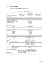
...MAP3367NC MAP3367NP Order number CA06200-B400 CA06200-B460 CA06200-B200 CA06200-B260 CA06200-B100 CA06200-B160 SCSI type SCA2, LVD 68-pin, LVD SCA2, LVD 68-pin, LVD SCA2, LVD 68-pin, LVD Capacity Number of Number of the SCSI. 2.1 Hardware Specifications...interface connector type when shipped. CHAPTER 2 SPECIFICATIONS 2.1 Hardware Specifications 2.2 SCSI Function Specifications This chapter describes specifications of the IDD and the functional specifications of Mounting (user area) disks heads screw 147.01 GB 4 8 73.50 GB 2 4 #6-32UNC 36.74 GB 1 2 The data format can be ...
...MAP3367NC MAP3367NP Order number CA06200-B400 CA06200-B460 CA06200-B200 CA06200-B260 CA06200-B100 CA06200-B160 SCSI type SCA2, LVD 68-pin, LVD SCA2, LVD 68-pin, LVD SCA2, LVD 68-pin, LVD Capacity Number of Number of the SCSI. 2.1 Hardware Specifications...interface connector type when shipped. CHAPTER 2 SPECIFICATIONS 2.1 Hardware Specifications 2.2 SCSI Function Specifications This chapter describes specifications of the IDD and the functional specifications of Mounting (user area) disks heads screw 147.01 GB 4 8 73.50 GB 2 4 #6-32UNC 36.74 GB 1 2 The data format can be ...
Manual/User Guide
Page 30
... (*7) LVD U160 Cable length: 25 m max (*8) Cable length: 12 m max (*9) Data transfer rate (*10) Disk drive SCSI Synchronous mode 64.1 to 528 byte (Fixed length) SCSI command specification SPI-4 (T10/1365D Rev.7), SAM-2 (T10/1157D Rev.20), SPC-2 (T10/1236D Rev.20), SBC (T10/996D Rev...30 s typ. 32/34 MEEPRML 25.4 mm 101.6 mm 146.0 mm 0.75 kg 9.6 W Cable length: 6 m max MAP3367NC/NP 36.74 GB 1 2 48,104 Single- Table 2.2 Function specifications Item Formatted capacity/device (*1) Number of disks Number of heads Number of cylinders (*2) Formatted capacity/track (B) Number of the IDD....
... (*7) LVD U160 Cable length: 25 m max (*8) Cable length: 12 m max (*9) Data transfer rate (*10) Disk drive SCSI Synchronous mode 64.1 to 528 byte (Fixed length) SCSI command specification SPI-4 (T10/1365D Rev.7), SAM-2 (T10/1157D Rev.20), SPC-2 (T10/1236D Rev.20), SBC (T10/996D Rev...30 s typ. 32/34 MEEPRML 25.4 mm 101.6 mm 146.0 mm 0.75 kg 9.6 W Cable length: 6 m max MAP3367NC/NP 36.74 GB 1 2 48,104 Single- Table 2.2 Function specifications Item Formatted capacity/device (*1) Number of disks Number of heads Number of cylinders (*2) Formatted capacity/track (B) Number of the IDD....
Manual/User Guide
Page 32
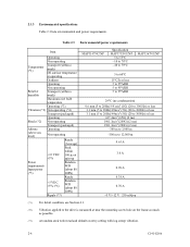
... Input power (about 80 (*5) IOPS) Ready +5 VDC ±5% (*6) Random W/R (about 80 IOPS) Ripple (*7) MAP3147NC/NP Specification MAP3735NC/NP 5 to 55°C -10 to 70°C -40 to 70°C MAP3367NC/NP 5 to 60°C 15°C/h or less 5 to 95%RH 5 to 95%RH 5 to 95%RH 29...-300 m to 3,000 m -300 m to 12,000 m 0.63 A 3.0 A 0.90 A 0.38 A 0.70 A +5 V/+12 V 250 mVp-p (*1) For detail condition, see Section 4.1. (*2) Vibration applied to the drive is measured at near the mounting screw hole on the frame as much as possible. (*3) At random seek write/read and default on retry setting...
... Input power (about 80 (*5) IOPS) Ready +5 VDC ±5% (*6) Random W/R (about 80 IOPS) Ripple (*7) MAP3147NC/NP Specification MAP3735NC/NP 5 to 55°C -10 to 70°C -40 to 70°C MAP3367NC/NP 5 to 60°C 15°C/h or less 5 to 95%RH 5 to 95%RH 5 to 95%RH 29...-300 m to 3,000 m -300 m to 12,000 m 0.63 A 3.0 A 0.90 A 0.38 A 0.70 A +5 V/+12 V 250 mVp-p (*1) For detail condition, see Section 4.1. (*2) Vibration applied to the drive is measured at near the mounting screw hole on the frame as much as possible. (*3) At random seek write/read and default on retry setting...
Manual/User Guide
Page 35
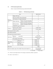
... MB/s max. Ο 40 MB/s max. Ο 80 MB/s max. Ο 160 MB/s max. Ο 320 MB/s max. C141-E166 2-7 Table 2.4 SCSI function specifications Item Specification Single-ended type Ο HVD type (High Voltage Differential) × Electrical LVD type (Low Voltage Differential) Ο requirements Single-ended type (*1) Position where the terminating...Synchronous mode) (LVD type) 16-bit SCSI (Single-ended type) (LVD type) (U160 LVD type) (U320 LVD type) #0 to (12) of Section 1.1. 2.2 SCSI Function Specifications Table 2.4 shows the SCSI functions provided with the IDD.
... MB/s max. Ο 40 MB/s max. Ο 80 MB/s max. Ο 160 MB/s max. Ο 320 MB/s max. C141-E166 2-7 Table 2.4 SCSI function specifications Item Specification Single-ended type Ο HVD type (High Voltage Differential) × Electrical LVD type (Low Voltage Differential) Ο requirements Single-ended type (*1) Position where the terminating...Synchronous mode) (LVD type) 16-bit SCSI (Single-ended type) (LVD type) (U160 LVD type) (U320 LVD type) #0 to (12) of Section 1.1. 2.2 SCSI Function Specifications Table 2.4 shows the SCSI functions provided with the IDD.
Manual/User Guide
Page 37
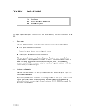
... 3.2 Logical Data Block Addressing 3.3 Defect Management This chapter explains data space definition, logical data block addressing, and defect management on or during the execution of a specific command, but user can be accessed with the logical data block addressing method described in the user space. See Subsection 3.1.2 for defective sectors are allocated...
... 3.2 Logical Data Block Addressing 3.3 Defect Management This chapter explains data space definition, logical data block addressing, and defect management on or during the execution of a specific command, but user can be accessed with the logical data block addressing method described in the user space. See Subsection 3.1.2 for defective sectors are allocated...
Manual/User Guide
Page 48
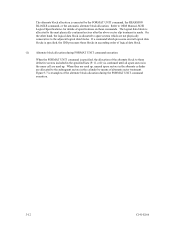
... sectors in the same cell are allocated to the adjacent logical data blocks. The logical data block is allocated to OEM Manual-SCSI Logical Specifications-for details of specifications on these commands. Refer to the next physically continued sectors after the above sector slip treatment is made. The alternate block allocation is...
... sectors in the same cell are allocated to the adjacent logical data blocks. The logical data block is allocated to OEM Manual-SCSI Logical Specifications-for details of specifications on these commands. Refer to the next physically continued sectors after the above sector slip treatment is made. The alternate block allocation is...
Manual/User Guide
Page 56
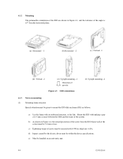
... to mount the IDD disk enclosure (DE) as follows. Mount the IDD with 0.59N·m (6kgf·cm) ±12%. e) Must be within the device specifications. 4.1.2 Mounting The permissible orientations of the IDD are shown in Figure 4.4, the inward projection of gravity Figure 4.3 IDD orientations (f) Upright mounting -2 4.1.3 Notes on an anti...
... to mount the IDD disk enclosure (DE) as follows. Mount the IDD with 0.59N·m (6kgf·cm) ±12%. e) Must be within the device specifications. 4.1.2 Mounting The permissible orientations of the IDD are shown in Figure 4.4, the inward projection of gravity Figure 4.3 IDD orientations (f) Upright mounting -2 4.1.3 Notes on an anti...
Manual/User Guide
Page 58
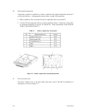
... not exceed 60°C. • Cool the PCA side especially with ambient temperature measured 3 cm from the disk drive. These measurement results should be within a criteria listed in Figures 4.7. 4-6 C141-E166 Measurement point 1 Center of specific ICs and the DE. (4) Environmental temperature Temperature condition at installed in a cabinet is shown in Table 4.1.
... not exceed 60°C. • Cool the PCA side especially with ambient temperature measured 3 cm from the disk drive. These measurement results should be within a criteria listed in Figures 4.7. 4-6 C141-E166 Measurement point 1 Center of specific ICs and the DE. (4) Environmental temperature Temperature condition at installed in a cabinet is shown in Table 4.1.
Manual/User Guide
Page 62
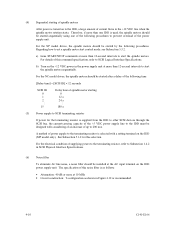
...noise, a noise filter should be installed at more than 12-second intervals to start the spindle motors. Regarding how to SCSI Logical Interface Specifications. For the NC model drives, the spindle motors should be started after a delay of the following time. [Delay time] = [SCSI ID] × 12 seconds... motor rotation starts. A method of up to 200 mA. For details of this command specification, refer to set a spindle motor start the spindle motors sequentially. For the NP model drives, the spindle motors should be started sequentially using one of the following procedures. b) Turn on...
...noise, a noise filter should be installed at more than 12-second intervals to start the spindle motors. Regarding how to SCSI Logical Interface Specifications. For the NC model drives, the spindle motors should be started after a delay of the following time. [Delay time] = [SCSI ID] × 12 seconds... motor rotation starts. A method of up to 200 mA. For details of this command specification, refer to set a spindle motor start the spindle motors sequentially. For the NP model drives, the spindle motors should be started sequentially using one of the following procedures. b) Turn on...
Manual/User Guide
Page 64
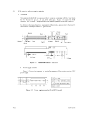
For details on the SCSI connector. Figure 4.15 Power supply connector (16-bit SCSI model) 4-12 C141-E166 See Section B.1 in the SCSI Physical Interface Specifications. (2) SCSI connector and power supply connector a. 16-bit SCSI The connector for the SCSI bus is an unshielded P connector conforming to Sections 1.3 and 1.4 in Appendix B ...
For details on the SCSI connector. Figure 4.15 Power supply connector (16-bit SCSI model) 4-12 C141-E166 See Section B.1 in the SCSI Physical Interface Specifications. (2) SCSI connector and power supply connector a. 16-bit SCSI The connector for the SCSI bus is an unshielded P connector conforming to Sections 1.3 and 1.4 in Appendix B ...
Manual/User Guide
Page 71
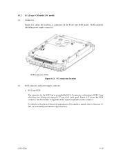
See Section B.2 in Appendix B for the SCSI bus is an unshielded SCA-2 connector conforming to Sections 1.3 and 1.4 in SCSI Physical Interface Specifications. For details on the physical/electrical requirements of connectors on the connector. SCSI connector (including power supply connector) SCSI connector (CN1) Figure 4.21 NC connectors ...
See Section B.2 in Appendix B for the SCSI bus is an unshielded SCA-2 connector conforming to Sections 1.3 and 1.4 in SCSI Physical Interface Specifications. For details on the physical/electrical requirements of connectors on the connector. SCSI connector (including power supply connector) SCSI connector (CN1) Figure 4.21 NC connectors ...
Manual/User Guide
Page 73
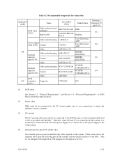
... HIROSE ELECTRIC A3B-2630SCC HIROSE ELECTRIC (AWG26 to 36) FCN-723J024/2M FUJITSU TAKAMIZAWA FCN-723J-G/AM FUJITSU TAKAMIZAWA (AWG28) 71780-003 FCI Reference (Figures 4.25 and 4.30) S1 S2 S3 S4 (1) SCSI cable See Section 1.3, "Physical Requirements", and Section 1.4, "Electrical Requirements", in SCSI Physical Interface Specifications. (2) Power cable IDDs must be star-connected...
... HIROSE ELECTRIC A3B-2630SCC HIROSE ELECTRIC (AWG26 to 36) FCN-723J024/2M FUJITSU TAKAMIZAWA FCN-723J-G/AM FUJITSU TAKAMIZAWA (AWG28) 71780-003 FCI Reference (Figures 4.25 and 4.30) S1 S2 S3 S4 (1) SCSI cable See Section 1.3, "Physical Requirements", and Section 1.4, "Electrical Requirements", in SCSI Physical Interface Specifications. (2) Power cable IDDs must be star-connected...
Manual/User Guide
Page 75
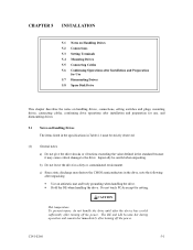
... PCAs except for use, and dismounting drives. 5.1 Notes on Handling Drives The items listed in the specifications in Table 2.1 must be careful when unpacking. CHAPTER 5 INSTALLATION 5.1 Notes on Handling Drives 5.2 Connections 5.3 Setting Terminals 5.4 Mounting Drives 5.5 Connecting Cables 5.6 Confirming Operations after Installation and Preparation for Use 5.7 Dismounting Drives 5.8 Spare Disk Drive This chapter describes the notes on handling...
... PCAs except for use, and dismounting drives. 5.1 Notes on Handling Drives The items listed in the specifications in Table 2.1 must be careful when unpacking. CHAPTER 5 INSTALLATION 5.1 Notes on Handling Drives 5.2 Connections 5.3 Setting Terminals 5.4 Mounting Drives 5.5 Connecting Cables 5.6 Confirming Operations after Installation and Preparation for Use 5.7 Dismounting Drives 5.8 Spare Disk Drive This chapter describes the notes on handling...
Manual/User Guide
Page 82
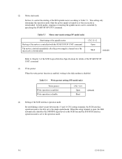
... operation mode is enabled, writing to the operation mode. 5-8 C141-E166 CN2 11-12 Open Short (default) Refer to Chapter 3 of the SCSI Logical Interface Specifications for details of the SCSI interface operation mode By establishing a short-circuit between the 15 and 16 CN2 setting terminals, the SCSI interface operation mode...
... operation mode is enabled, writing to the operation mode. 5-8 C141-E166 CN2 11-12 Open Short (default) Refer to Chapter 3 of the SCSI Logical Interface Specifications for details of the SCSI interface operation mode By establishing a short-circuit between the 15 and 16 CN2 setting terminals, the SCSI interface operation mode...
Manual/User Guide
Page 83
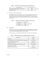
This setup terminal must be set to the 8-bit bus mode. Refer to Section 3.1.4 of the SCSI Logical Interface Specifications for the IDD SCSI interface is provided with several mode settings. The mode settings are enabled by CHANGE DEFINITION command) Mode setting SCSI level SYNCHRONOUS ...
This setup terminal must be set to the 8-bit bus mode. Refer to Section 3.1.4 of the SCSI Logical Interface Specifications for the IDD SCSI interface is provided with several mode settings. The mode settings are enabled by CHANGE DEFINITION command) Mode setting SCSI level SYNCHRONOUS ...
