

Manual/User Guide
Page 2
Specification No.: C141-E064-**EN The contents of this manual is subject to change without prior notice. REVISION RECORD Edition Date published Revised contents 01 Nov., 1998 02 May, 1999 03 Oct., 1999 MC/MP types are added. All Rights Reserved. Copyright © 1999 FUJITSU LIMITED C141-E064-03EN i
Specification No.: C141-E064-**EN The contents of this manual is subject to change without prior notice. REVISION RECORD Edition Date published Revised contents 01 Nov., 1998 02 May, 1999 03 Oct., 1999 MC/MP types are added. All Rights Reserved. Copyright © 1999 FUJITSU LIMITED C141-E064-03EN i
Manual/User Guide
Page 4
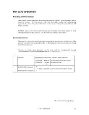
... EPROM Standard INQUIRY Data Product Version No. Version Revision (ASCII) No. FOR SAFE OPERATION Handling of the products covered by Fujitsu. Use this product only after thoroughly reading and understanding especially the section "Important Alert Items" in the current version. (Proceed...RAM Command WRITE RAM Command These commands cannot be certain functional limitations concerning the specifications and functions of This manual This manual contains important information for using the product. FUJITSU makes every effort to prevent users and bystanders from being injured or from ...
... EPROM Standard INQUIRY Data Product Version No. Version Revision (ASCII) No. FOR SAFE OPERATION Handling of the products covered by Fujitsu. Use this product only after thoroughly reading and understanding especially the section "Important Alert Items" in the current version. (Proceed...RAM Command WRITE RAM Command These commands cannot be certain functional limitations concerning the specifications and functions of This manual This manual contains important information for using the product. FUJITSU makes every effort to prevent users and bystanders from being injured or from ...
Manual/User Guide
Page 5
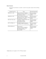
...System Interface - 2(SCSI-2) (ANSI) COMMON COMMAND SET (CCS) American National of products covered by this manual comply with the following standards. Related Standards Specifications and functions of the Small Computer Standards Institute System Interface (SCSI) (ANSI) WORKING DRAFT Information American National Technology SCSI-3 Parallel Interface Standards Institute (ANSI)... Systems-SCSI-3 Fast-20 Parallel Interface (Fast 20-SCSI) American National Standards Institute (ANSI) All Right Reserved, Copyright © 1998, 1999 Fujitsu Limited iv C141-E064-03EN Standard (Text) No.
...System Interface - 2(SCSI-2) (ANSI) COMMON COMMAND SET (CCS) American National of products covered by this manual comply with the following standards. Related Standards Specifications and functions of the Small Computer Standards Institute System Interface (SCSI) (ANSI) WORKING DRAFT Information American National Technology SCSI-3 Parallel Interface Standards Institute (ANSI)... Systems-SCSI-3 Fast-20 Parallel Interface (Fast 20-SCSI) American National Standards Institute (ANSI) All Right Reserved, Copyright © 1998, 1999 Fujitsu Limited iv C141-E064-03EN Standard (Text) No.

Manual/User Guide
Page 6
...electrical requirements for setting device number and operation modes, mounting the disk drive, connecting the cables, and confirming drive operation. This manual details the specifications and functions of the above disk drive, and gives the requirements and procedures for users who have a suffix... describes the electrical requirements of fixed disk drives and their installation environment. C141-E064-03EN v PREFACE This manual describes the MAF3364LC/LP/MC/MP (hereafter, MAF series), MAE3182LC/LP, MAE3091LC/LP, (hereafter, MAE series), and MAG3182LC/LP/MC/MP, MAG3091LC/LP/MC/MP...
...electrical requirements for setting device number and operation modes, mounting the disk drive, connecting the cables, and confirming drive operation. This manual details the specifications and functions of the above disk drive, and gives the requirements and procedures for users who have a suffix... describes the electrical requirements of fixed disk drives and their installation environment. C141-E064-03EN v PREFACE This manual describes the MAF3364LC/LP/MC/MP (hereafter, MAF series), MAE3182LC/LP, MAE3091LC/LP, (hereafter, MAE series), and MAG3182LC/LP/MC/MP, MAG3091LC/LP/MC/MP...
Manual/User Guide
Page 10
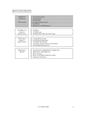
... Operation C141-E064-03EN ix Installation 6. SCSI Bus 2. Maintenance and Diagnostics 3. MANUAL ORGANIZATION PRODUCT MANUAL (This manual) SCSI Physical Interface Specifications SCSI Logical Interface Specifications Maintenance Manual 1. Data Buffer Management 3. General Description 2. Command Specification 4. Error Analysis 4. Removal and Replacement Procedures 5. Data Format 4. Installation Requirements 5. Diagnostics and Maintenance 1. Sense Data and error Recovery Procedure...
... Operation C141-E064-03EN ix Installation 6. SCSI Bus 2. Maintenance and Diagnostics 3. MANUAL ORGANIZATION PRODUCT MANUAL (This manual) SCSI Physical Interface Specifications SCSI Logical Interface Specifications Maintenance Manual 1. Data Buffer Management 3. General Description 2. Command Specification 4. Error Analysis 4. Removal and Replacement Procedures 5. Data Format 4. Installation Requirements 5. Diagnostics and Maintenance 1. Sense Data and error Recovery Procedure...

Manual/User Guide
Page 12
CONTENTS page CHAPTER 1 GENERAL DESCRIPTION 1-1 1.1 Standard Features ...1-2 1.2 Hardware Structure...1-5 1.3 System Configuration...1-10 CHAPTER 2 SPECIFICATIONS 2-1 2.1 Hardware Specifications 2-1 2.1.1 Model name and part number 2-1 2.1.2 Function specifications 2-2 2.1.3 Environmental specifications 2-4 2.1.4 Error rate...2-5 2.1.5 Reliability ...2-5 2.2 SCSI Function Specifications 2-7 CHAPTER 3 DATA FORMAT 3-1 3.1 Data Space...3-1 3.1.1 Cylinder configuration...3-1 3.1.2 Alternate spare area ...3-5 3.1.3 Track format ...3-6 3.1.4 Sector format ...3-8 3.1.5 Format capacity ...3-10...
CONTENTS page CHAPTER 1 GENERAL DESCRIPTION 1-1 1.1 Standard Features ...1-2 1.2 Hardware Structure...1-5 1.3 System Configuration...1-10 CHAPTER 2 SPECIFICATIONS 2-1 2.1 Hardware Specifications 2-1 2.1.1 Model name and part number 2-1 2.1.2 Function specifications 2-2 2.1.3 Environmental specifications 2-4 2.1.4 Error rate...2-5 2.1.5 Reliability ...2-5 2.2 SCSI Function Specifications 2-7 CHAPTER 3 DATA FORMAT 3-1 3.1 Data Space...3-1 3.1.1 Cylinder configuration...3-1 3.1.2 Alternate spare area ...3-5 3.1.3 Track format ...3-6 3.1.4 Sector format ...3-8 3.1.5 Format capacity ...3-10...

Manual/User Guide
Page 17
TABLES page 2.1 Function specifications 2-2 2.2 Environmental/power requirements 2-4 2.3 SCSI function specifications 2-7 3.1 Zone layout and track capacity (MAE series 3-3 3.2 Zone layout and track capacity (MAG series 3-3 3.3 Zone layout and track capacity (MAF series 3-3 3.4 Format capacity ...3-10 4.1 Surface ...
TABLES page 2.1 Function specifications 2-2 2.2 Environmental/power requirements 2-4 2.3 SCSI function specifications 2-7 3.1 Zone layout and track capacity (MAE series 3-3 3.2 Zone layout and track capacity (MAG series 3-3 3.3 Zone layout and track capacity (MAF series 3-3 3.4 Format capacity ...3-10 4.1 Surface ...
Manual/User Guide
Page 19
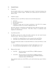
... functions. (3) 8-bit SCSI/16-bit SCSI The IDD has 16-bit data bus width (16-bit SCSI), which meets the logical specification of the disk drive. The IDD can manipulate data through logical block addressing regardless of the physical characteristics of the SCSI CCS (Common Command Set for Direct ... High speed data transfer • 8-bit SCSI: The data transfer rate on the SCSI bus is 40 MB/s maximum in the standard 3.5-inch fixed disk drive form factor, the IDD is extremely compact. This is also available as follows. • Up to 4 SCSI devices having capacitance of 25 pF: Cable length...
... functions. (3) 8-bit SCSI/16-bit SCSI The IDD has 16-bit data bus width (16-bit SCSI), which meets the logical specification of the disk drive. The IDD can manipulate data through logical block addressing regardless of the physical characteristics of the SCSI CCS (Common Command Set for Direct ... High speed data transfer • 8-bit SCSI: The data transfer rate on the SCSI bus is 40 MB/s maximum in the standard 3.5-inch fixed disk drive form factor, the IDD is extremely compact. This is also available as follows. • Up to 4 SCSI devices having capacitance of 25 pF: Cable length...

Manual/User Guide
Page 20
The continuous processing up to prevent a specific command from the data buffer without concerning the physical structure of the track or cylinder boundaries. This feature provides the suitable usage environment for MC/... perform continuous read/write operation when processing data blocks on the SCSI bus by the response time of initiator and the length of the disk drive. (7) Read-ahead cache feature After executing the READ command, the IDD reads automatically and stores (prefetches) the subsequent data blocks into 1 to the data buffer...
The continuous processing up to prevent a specific command from the data buffer without concerning the physical structure of the track or cylinder boundaries. This feature provides the suitable usage environment for MC/... perform continuous read/write operation when processing data blocks on the SCSI bus by the response time of initiator and the length of the disk drive. (7) Read-ahead cache feature After executing the READ command, the IDD reads automatically and stores (prefetches) the subsequent data blocks into 1 to the data buffer...

Manual/User Guide
Page 30
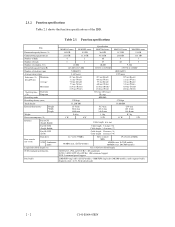
C141-E064-03EN 2 - 1 CHAPTER 2 SPECIFICATIONS 2.1 Hardware Specifications 2.2 SCSI Function Specifications This chapter describes specifications of the IDD and the functional specifications of the SCSI. 2.1 Hardware Specifications 2.1.1 Model name and part number Each model has a different data format and front panel type when shipped. (See Appendix D for the model name (type) and product number.) The data format can be changed by reinitializing with the user's system.
C141-E064-03EN 2 - 1 CHAPTER 2 SPECIFICATIONS 2.1 Hardware Specifications 2.2 SCSI Function Specifications This chapter describes specifications of the IDD and the functional specifications of the SCSI. 2.1 Hardware Specifications 2.1.1 Model name and part number Each model has a different data format and front panel type when shipped. (See Appendix D for the model name (type) and product number.) The data format can be changed by reinitializing with the user's system.
Manual/User Guide
Page 31
... SCSI (Single-Ended) Fast 20 SCSI (Single-Ended) Fast 80 SCSI (LVD) Data transfer rate (*10) Disk drive SCSI Synchronous mode Logical data block length (*1) SCSI command specification Data buffer MAE3182 series MAE3091 series 18.2 GB 9.1 GB 23.1 GB 11.5 GB 4 2 8 4 12,000 143,360 to 217,600 7,200±0.5% 4.167 msec 0.7 ms (Read)/ 1.1 ms (Write) 7.0 ms...
... SCSI (Single-Ended) Fast 20 SCSI (Single-Ended) Fast 80 SCSI (LVD) Data transfer rate (*10) Disk drive SCSI Synchronous mode Logical data block length (*1) SCSI command specification Data buffer MAE3182 series MAE3091 series 18.2 GB 9.1 GB 23.1 GB 11.5 GB 4 2 8 4 12,000 143,360 to 217,600 7,200±0.5% 4.167 msec 0.7 ms (Read)/ 1.1 ms (Write) 7.0 ms...

Manual/User Guide
Page 33
2.1.3 Environmental specifications Table 2.2 lists environmental and power requirements. Table 2.2 Environmental/power requirements Temperature (*1) Relative humidity Vibration (*2) Shock (*2) Altitute (above sea level... A 1.3 A 1.0 A +5 VDC ±5% (*6) Ready 0.6 A 0.8 A 0.7 A Random W/R (about 80 IOPS) 6.8 A 1.0 A 0.9 A Ripple (*7) +5 V 250 mVp-p, +12 V 250 mVp-p (*1) For detail condition, see Section 4.1. (*2) Vibration applied to the drive is measured at near the mounting screw hole on the frame as much as possible. (*3) At random seek write/read and default on retry setting...
2.1.3 Environmental specifications Table 2.2 lists environmental and power requirements. Table 2.2 Environmental/power requirements Temperature (*1) Relative humidity Vibration (*2) Shock (*2) Altitute (above sea level... A 1.3 A 1.0 A +5 VDC ±5% (*6) Ready 0.6 A 0.8 A 0.7 A Random W/R (about 80 IOPS) 6.8 A 1.0 A 0.9 A Ripple (*7) +5 V 250 mVp-p, +12 V 250 mVp-p (*1) For detail condition, see Section 4.1. (*2) Vibration applied to the drive is measured at near the mounting screw hole on the frame as much as possible. (*3) At random seek write/read and default on retry setting...

Manual/User Guide
Page 36
2.2 SCSI Function Specifications Table 2.3 shows the SCSI functions provided with the IDD. C141-E064-03EN 2 - 7 segment buffer (1 to 32) Data block length (Logical data length=Physical data length) (*3) ...-bit SCSI LUN (logical unit number) #0 to (12) of Section 1.1. Data buffer 2 MB (LC/LP) or 4 MB (MC/MP) programmable multi- Table 2.3 SCSI function specifications Item Specification Single-ended type Ο HVD type (High Voltage Differential) × LVD type (Low Voltage Differential) Ο Electrical requirements Single-ended type Position where the terminating...
2.2 SCSI Function Specifications Table 2.3 shows the SCSI functions provided with the IDD. C141-E064-03EN 2 - 7 segment buffer (1 to 32) Data block length (Logical data length=Physical data length) (*3) ...-bit SCSI LUN (logical unit number) #0 to (12) of Section 1.1. Data buffer 2 MB (LC/LP) or 4 MB (MC/MP) programmable multi- Table 2.3 SCSI function specifications Item Specification Single-ended type Ο HVD type (High Voltage Differential) × LVD type (Low Voltage Differential) Ο Electrical requirements Single-ended type Position where the terminating...

Manual/User Guide
Page 38
... 3.2 Logical Data Block Addressing 3.3 Defect Management This chapter explains data space definition, logical data block addressing, and defect management on or during the execution of a specific command, but user can be accessed with the logical data block addressing method described in the user space are provided in the user space. Figure...
... 3.2 Logical Data Block Addressing 3.3 Defect Management This chapter explains data space definition, logical data block addressing, and defect management on or during the execution of a specific command, but user can be accessed with the logical data block addressing method described in the user space are provided in the user space. Figure...

Manual/User Guide
Page 50
Refer to OEM Manual-SCSI Logical Specifications-for details of the alternate block to the adjacent logical data blocks. If a command which are used up, unused spare sectors in the alternate cylinder ... alternate block allocation is examples of the alternate block allocation during FORMAT UNIT command execution When the FORMAT UNIT command is specified, the allocation of specifications on these commands. On the other hand, the logical data block is allocated to the next physically continued sectors after the above sector slip treatment...
Refer to OEM Manual-SCSI Logical Specifications-for details of the alternate block to the adjacent logical data blocks. If a command which are used up, unused spare sectors in the alternate cylinder ... alternate block allocation is examples of the alternate block allocation during FORMAT UNIT command execution When the FORMAT UNIT command is specified, the allocation of specifications on these commands. On the other hand, the logical data block is allocated to the next physically continued sectors after the above sector slip treatment...

Manual/User Guide
Page 61
...;5° from the IDD frame wall at the corner must be 4 mm or less. d) Impact caused by the electric driver must be within the device specifications. Mount the IDD with 6kg-cm. c) Tightening torque of screw must be secured with making a gap of 2.5 mm or more between the IDD and the...
...;5° from the IDD frame wall at the corner must be 4 mm or less. d) Impact caused by the electric driver must be within the device specifications. Mount the IDD with 6kg-cm. c) Tightening torque of screw must be secured with making a gap of 2.5 mm or more between the IDD and the...

Manual/User Guide
Page 63
Measurement point 1 Center of specific ICs and the DE. These measurement results should be maintained to deal with air circulation inside the cabinet. At designing the system cabinet, consider following ... temperature Temperature condition at 45°C (Center of DE cover 55°C). • Cool the PCA side especially with much heat generated from the disk drive. Table 4.1 Surface temperature check point No.
Measurement point 1 Center of specific ICs and the DE. These measurement results should be maintained to deal with air circulation inside the cabinet. At designing the system cabinet, consider following ... temperature Temperature condition at 45°C (Center of DE cover 55°C). • Cool the PCA side especially with much heat generated from the disk drive. Table 4.1 Surface temperature check point No.

Manual/User Guide
Page 68
... more than 12-second intervals to start the spindle motors sequentially. (5) Power supply to SCSI terminating resistor If power for this command specification, refer to start control mode, see Subsection 5.3.2. For details of current flows in the power supply unit at 10 MHz •... Circuit construction: T-configuration as follows: • Attenuation: 40 dB or more at more than 12-second intervals to SCSI Logical Interface Specifications. a) Issue START/STOP commands at more than one of the following procedures to 200 mA. Figure 4.17 AC noise filter (recommended) C141...
... more than 12-second intervals to start the spindle motors sequentially. (5) Power supply to SCSI terminating resistor If power for this command specification, refer to start control mode, see Subsection 5.3.2. For details of current flows in the power supply unit at 10 MHz •... Circuit construction: T-configuration as follows: • Attenuation: 40 dB or more at more than 12-second intervals to SCSI Logical Interface Specifications. a) Issue START/STOP commands at more than one of the following procedures to 200 mA. Figure 4.17 AC noise filter (recommended) C141...

Manual/User Guide
Page 70
...-bit SCSI interface connector b. For details on the SCSI connector. The tolerance is an unshielded P connector conforming to Sections 1.3 and 1.4 in the SCSI Physical Interface Specifications. (2) SCSI connector and power supply connector a. 16-bit SCSI The connector for the signal assignments on the physical/electrical requirements of DC power supply.
...-bit SCSI interface connector b. For details on the SCSI connector. The tolerance is an unshielded P connector conforming to Sections 1.3 and 1.4 in the SCSI Physical Interface Specifications. (2) SCSI connector and power supply connector a. 16-bit SCSI The connector for the signal assignments on the physical/electrical requirements of DC power supply.

Manual/User Guide
Page 74
... pin) These signals actuate the external LED as same as LED on the front panel of command, refer to SCSI Logical Interface Specifications. 2. For details of the disk drive. This signal is temporarily driven at the GND level when the micro program reads the SCSI ID immediately after the power supply to... the write-protect status is in effect (CN1-A12 is connected to the GND, or the CN2-9 and CN2-10 are short-circuited.) A signal for driving the LED is output. 74LS06 or equivalent 150 Ω (IDD) NC1-A2 IMPORTANT This signal is temporarily driven at the GND level when the micro...
... pin) These signals actuate the external LED as same as LED on the front panel of command, refer to SCSI Logical Interface Specifications. 2. For details of the disk drive. This signal is temporarily driven at the GND level when the micro program reads the SCSI ID immediately after the power supply to... the write-protect status is in effect (CN1-A12 is connected to the GND, or the CN2-9 and CN2-10 are short-circuited.) A signal for driving the LED is output. 74LS06 or equivalent 150 Ω (IDD) NC1-A2 IMPORTANT This signal is temporarily driven at the GND level when the micro...
