User manual
Page 5
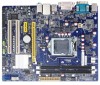
... motherboard and CPU due to come in your device. ■ If there is any, when connecting USB, audio, 1394a, RS232 COM, IrDA or S/PDIF cables to the internal connectors on the motherboard, make sure their pinouts are uncertain about any installation steps or have a problem related to the use of your system, we recommend using a 24-pin ATX power supply to get the best performance. ■ Before turning on the power...
... motherboard and CPU due to come in your device. ■ If there is any, when connecting USB, audio, 1394a, RS232 COM, IrDA or S/PDIF cables to the internal connectors on the motherboard, make sure their pinouts are uncertain about any installation steps or have a problem related to the use of your system, we recommend using a 24-pin ATX power supply to get the best performance. ■ Before turning on the power...
User manual
Page 6
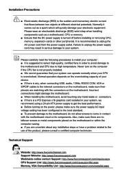
... Specifications 2 1-2 Layout...4 1-3 Back Panel Connectors 5 Chapter 2 Hardware Installation 2-1 Install the CPU and CPU Cooler 8 Install the CPU 8 Install the CPU Cooler 10 2-2 Install the Memory 11 Dual Channel Memory Configuration 11 Installing a Memory 12 2-3 Install an Expansion Card 13 2-4 Install other Internal Connectors 14 2-5 Jumpers 18 Chapter 3 BIOS Setup Enter BIOS Setup 21 Main...22 F-center...24 Smart BIOS 24 Fox Intelligent Stepping 25 CPU Configuration 26 Performance Tuning 27 Advanced...29 North Bridge 29 ME Subsystem 30 Onboard Device Configuration 31 SATA...
... Specifications 2 1-2 Layout...4 1-3 Back Panel Connectors 5 Chapter 2 Hardware Installation 2-1 Install the CPU and CPU Cooler 8 Install the CPU 8 Install the CPU Cooler 10 2-2 Install the Memory 11 Dual Channel Memory Configuration 11 Installing a Memory 12 2-3 Install an Expansion Card 13 2-4 Install other Internal Connectors 14 2-5 Jumpers 18 Chapter 3 BIOS Setup Enter BIOS Setup 21 Main...22 F-center...24 Smart BIOS 24 Fox Intelligent Stepping 25 CPU Configuration 26 Performance Tuning 27 Advanced...29 North Bridge 29 ME Subsystem 30 Onboard Device Configuration 31 SATA...
User manual
Page 9
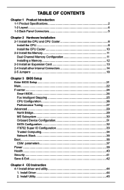
... 1-1 Product Specifications CPU Chipset Memory Expansion Slots Storage LAN Audio USB Internal Connectors Support Intel® Ivy Bridge/Sandy Bridge LGA1155 Processors Max processor power up to 95W For the latest CPU information, please visit: http://www.foxconnsupport.com/cpusupportlist.aspx Intel® B75 2 x 240-pin DDR3 DIMMs Support up to 16GB of system memory Dual channel DDR3 1600(IVB)/1333 MHz architecture 1 x PCI Express X16 slot -Support PCI Express Gen2 5GT/s data rate (Sandy Bridge) -Support PCI Express Gen3 8GT...
... 1-1 Product Specifications CPU Chipset Memory Expansion Slots Storage LAN Audio USB Internal Connectors Support Intel® Ivy Bridge/Sandy Bridge LGA1155 Processors Max processor power up to 95W For the latest CPU information, please visit: http://www.foxconnsupport.com/cpusupportlist.aspx Intel® B75 2 x 240-pin DDR3 DIMMs Support up to 16GB of system memory Dual channel DDR3 1600(IVB)/1333 MHz architecture 1 x PCI Express X16 slot -Support PCI Express Gen2 5GT/s data rate (Sandy Bridge) -Support PCI Express Gen3 8GT...

User manual
Page 14
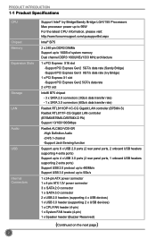
Chapter 2 Hardware Installation This chapter introduces the hardware installation process, including the installation of the CPU, memory, power supply, slots, pin headers and the mounting of these modules. This chapter includes the following information : ■ Install the CPU and CPU Cooler ■ Install the Memory ■ Install an Expansion Card ■ Install other Internal Connectors ■ Jumpers Please refer to the motherboard layout prior to any installation and read the contents in this chapter carefully...
Chapter 2 Hardware Installation This chapter introduces the hardware installation process, including the installation of the CPU, memory, power supply, slots, pin headers and the mounting of these modules. This chapter includes the following information : ■ Install the CPU and CPU Cooler ■ Install the Memory ■ Install an Expansion Card ■ Install other Internal Connectors ■ Jumpers Please refer to the motherboard layout prior to any installation and read the contents in this chapter carefully...
User manual
Page 20
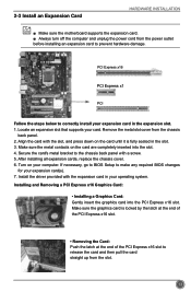
... expansion slot. 1. After installing all expansion cards, replace the chassis cover. 6. 2-3 Install an Expansion Card HARDWARE INSTALLATION ■ Make sure the motherboard supports the expansion card. ■ Always turn off the computer and unplug the power cord from the power outlet before installing an expansion card to the chassis back panel with a screw. 5. Installing and Removing a PCI Express x16 Graphics Card: • Installing a Graphics Card: Gently insert the graphics card into the slot. 4. Remove the metal slot cover from the chassis back panel. 2. Turn on...
... expansion slot. 1. After installing all expansion cards, replace the chassis cover. 6. 2-3 Install an Expansion Card HARDWARE INSTALLATION ■ Make sure the motherboard supports the expansion card. ■ Always turn off the computer and unplug the power cord from the power outlet before installing an expansion card to the chassis back panel with a screw. 5. Installing and Removing a PCI Express x16 Graphics Card: • Installing a Graphics Card: Gently insert the graphics card into the slot. 4. Remove the metal slot cover from the chassis back panel. 2. Turn on...
User manual
Page 23
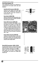
... than using the power supply button. 12 + HDD-LED - + - HARDWARE INSTALLATION Front Panel Header: FP1 This motherboard includes one connector for connecting the front panel switch and LED Indicators. Hard Disk LED Connector (HDD-LED) Connect to 6GB/s data transfer rate. 1 GND TX+ TXGND RXRX+ GND 1 GND TX+ TXGND RXRX+ GND SATA_1 SATA_2/3/4 16 The Power LED indicates the system's status. This 2-pin connector is directional with SATA Hard Disk or CD devices which support this switch allows the system to the Reset switch...
... than using the power supply button. 12 + HDD-LED - + - HARDWARE INSTALLATION Front Panel Header: FP1 This motherboard includes one connector for connecting the front panel switch and LED Indicators. Hard Disk LED Connector (HDD-LED) Connect to 6GB/s data transfer rate. 1 GND TX+ TXGND RXRX+ GND 1 GND TX+ TXGND RXRX+ GND SATA_1 SATA_2/3/4 16 The Power LED indicates the system's status. This 2-pin connector is directional with SATA Hard Disk or CD devices which support this switch allows the system to the Reset switch...
User manual
Page 25
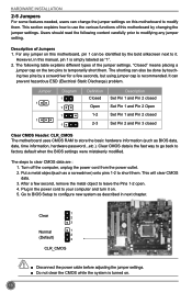
... shorting can be done by touching two pins by a screwdriver for a few second, remove the metal object to clear CMOS data are : 1. Jumper 1 1 Diagram 1 1 1 1 Definition Closed Open 1-2 2-3 Description Set Pin 1 and Pin 2 closed Set Pin 1 and Pin 2 Open Set Pin 1 and Pin 2 closed Set Pin 2 and Pin 3 closed Clear CMOS Header: CLR_CMOS The motherboard uses CMOS RAM to store the basic hardware information (such as a screwdriver) onto pins 1-2 to factory default when the BIOS settings were mistakenly modified. Go to BIOS Setup...
... shorting can be done by touching two pins by a screwdriver for a few second, remove the metal object to clear CMOS data are : 1. Jumper 1 1 Diagram 1 1 1 1 Definition Closed Open 1-2 2-3 Description Set Pin 1 and Pin 2 closed Set Pin 1 and Pin 2 Open Set Pin 1 and Pin 2 closed Set Pin 2 and Pin 3 closed Clear CMOS Header: CLR_CMOS The motherboard uses CMOS RAM to store the basic hardware information (such as a screwdriver) onto pins 1-2 to factory default when the BIOS settings were mistakenly modified. Go to BIOS Setup...

User manual
Page 26
...; AMT, that allows to pins 2-3 first. 19 Set the jumper to enable or disable Intel® Management Engine function. HARDWARE INSTALLATION Intel® ME Jumper: PCH_ME_ENABLE This motherboard uses this jumper to pins 1-2, you can disable the Intel® Management Engine function. 1 Enable 2 (Default) 3 1 Disable 2 3 PCH_ME_ENABLE Definition 1-2(default) 2-3 Description Set Pin 1 and Pin 2 closed Set Pin 2 and Pin 3 closed Function Enable ME function Disable ME function CAUTION Before flashing BIOS ROM, you can enable the Intel® Management...
...; AMT, that allows to pins 2-3 first. 19 Set the jumper to enable or disable Intel® Management Engine function. HARDWARE INSTALLATION Intel® ME Jumper: PCH_ME_ENABLE This motherboard uses this jumper to pins 1-2, you can disable the Intel® Management Engine function. 1 Enable 2 (Default) 3 1 Disable 2 3 PCH_ME_ENABLE Definition 1-2(default) 2-3 Description Set Pin 1 and Pin 2 closed Set Pin 2 and Pin 3 closed Function Enable ME function Disable ME function CAUTION Before flashing BIOS ROM, you can enable the Intel® Management...
User manual
Page 28
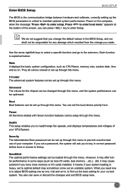
... and error, to find out the best setting for your system loading is heavy, set a password, the system will ask you can be responsible for the chipset can be changed through this menu, and the system performance can be optimized. Health This setup enables you to read/change fan speeds, and displays temperatures and voltages of the screen, you to key in some ways (such as CPU Name, memory size, system...
... and error, to find out the best setting for your system loading is heavy, set a password, the system will ask you can be responsible for the chipset can be changed through this menu, and the system performance can be optimized. Health This setup enables you to read/change fan speeds, and displays temperatures and voltages of the screen, you to key in some ways (such as CPU Name, memory size, system...
User manual
Page 31
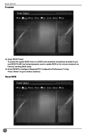
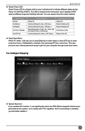
...improperly used to update BIOS or the vicious virus(such as CHI,etc) rewriting BIOS setup. ► Smart BIOS/Fox Intelligent Stepping/CPU Configuration/Performance Tuning Press to go to relative submenu. Smart BIOS Main F-center Advanced Boot Smart BIOS Power Health Smart Power LED Smart Boot Menu [Disabled] [Enabled] Security Save&Exit Smart Power LED Settings 24 → ←: Select Screen ↑ ↓: Select Item Enter: Select +/-: Change Opt. BIOS SETUP F-center Main F-center Advanced Boot Fox Control Center Super BIOS Protect ▶ Smart BIOS ▶...
...improperly used to update BIOS or the vicious virus(such as CHI,etc) rewriting BIOS setup. ► Smart BIOS/Fox Intelligent Stepping/CPU Configuration/Performance Tuning Press to go to relative submenu. Smart BIOS Main F-center Advanced Boot Smart BIOS Power Health Smart Power LED Smart Boot Menu [Disabled] [Enabled] Security Save&Exit Smart Power LED Settings 24 → ←: Select Screen ↑ ↓: Select Item Enter: Select +/-: Change Opt. BIOS SETUP F-center Main F-center Advanced Boot Fox Control Center Super BIOS Protect ▶ Smart BIOS ▶...
User manual
Page 32
... On Reboot & Memory OK Reboot & Display OK Enter Setup or Skip Reboot & Fan OK ► Smart Boot Menu When PC starts, it will ask you had better disable it displays POST state by the system, so to enter smart boot menu. But if overclocking is selected, then pressing [F7] has no function. F1: General Help F2: Previous Values F3: Optimized Defaults F4: Save & Exit ESC: Exit Version 2.15.1234...
... On Reboot & Memory OK Reboot & Display OK Enter Setup or Skip Reboot & Fan OK ► Smart Boot Menu When PC starts, it will ask you had better disable it displays POST state by the system, so to enter smart boot menu. But if overclocking is selected, then pressing [F7] has no function. F1: General Help F2: Previous Values F3: Optimized Defaults F4: Save & Exit ESC: Exit Version 2.15.1234...
User manual
Page 33
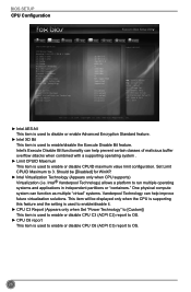
BIOS SETUP CPU Configuration Main F-center Advanced Boot CPU Configuration CPU Brand Name: Genuine Intel(R) CPU @ 2.20GHz L1 Data Cache L1 Code Cache L2 Cache L3 Cache Processor Stepping Max CPU Speed Min CPU Speed Current CPU Speed Processor Cores Intel HT Technology Intel VT-x Technology Intel SMX Technology Intel AES-NI Intel XD Bit Limit CPUID Maximum Intel Virtualization Technology CPU C3 Report CPU C6 report Power Health 32 KB X 4 32 KB X 4 256 KB X 4 8192 KB 4 2200 MHZ 1600 MHz...
BIOS SETUP CPU Configuration Main F-center Advanced Boot CPU Configuration CPU Brand Name: Genuine Intel(R) CPU @ 2.20GHz L1 Data Cache L1 Code Cache L2 Cache L3 Cache Processor Stepping Max CPU Speed Min CPU Speed Current CPU Speed Processor Cores Intel HT Technology Intel VT-x Technology Intel SMX Technology Intel AES-NI Intel XD Bit Limit CPUID Maximum Intel Virtualization Technology CPU C3 Report CPU C6 report Power Health 32 KB X 4 32 KB X 4 256 KB X 4 8192 KB 4 2200 MHZ 1600 MHz...
User manual
Page 34
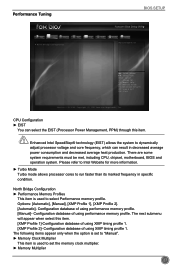
... following items appear only when the option is set to "Manual". ► Memory Clock Multiplier This item is used to select Performance memory profile. Performance Tuning BIOS SETUP Main F-center Advanced Boot Power Health Security Save&Exit ▶ CPU Configuration ▶ North Bridge Configuration CPU Configuration CAUTION → ←: Select Screen ↑ ↓: Select Item Enter: Select +/-: Change Opt. CPU Configuration ► EIST You can result in specific condition. The next submenu will...
... following items appear only when the option is set to "Manual". ► Memory Clock Multiplier This item is used to select Performance memory profile. Performance Tuning BIOS SETUP Main F-center Advanced Boot Power Health Security Save&Exit ▶ CPU Configuration ▶ North Bridge Configuration CPU Configuration CAUTION → ←: Select Screen ↑ ↓: Select Item Enter: Select +/-: Change Opt. CPU Configuration ► EIST You can result in specific condition. The next submenu will...
User manual
Page 37
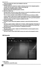
...; Virtualization Technology for the integrated graphics controller from the system memory. ME Subsystem Main F-center Advanced Boot Intel ME Subsystem Configuration ME Version Power Health 8.1.20.1336 Security Save&Exit → ←: Select Screen ↑ ↓: Select Item Enter: Select +/-: Change Opt. Options: [Auto], [Manual]. [Auto]-Auto the integrated graphics controller. [Manual]- F1: General Help F2: Previous Values F3: Optimized Defaults F4: Save & Exit ESC: Exit Version 2.15.1234. BIOS SETUP These items display the memory size installed on...
...; Virtualization Technology for the integrated graphics controller from the system memory. ME Subsystem Main F-center Advanced Boot Intel ME Subsystem Configuration ME Version Power Health 8.1.20.1336 Security Save&Exit → ←: Select Screen ↑ ↓: Select Item Enter: Select +/-: Change Opt. Options: [Auto], [Manual]. [Auto]-Auto the integrated graphics controller. [Manual]- F1: General Help F2: Previous Values F3: Optimized Defaults F4: Save & Exit ESC: Exit Version 2.15.1234. BIOS SETUP These items display the memory size installed on...
User manual
Page 38
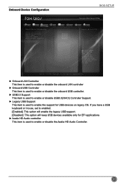
... Defaults F4: Save & Exit ESC: Exit Version 2.15.1234. If you have a USB keyboard or mouse, set to enabled. [Enabled]: This option will enable the legacy USB support. [Disabled]: This option will keep USB devices available only for EFI applications. ► Azalia HD Audio controller This item is used to enable the support for USB devices on legacy OS. Onboard Device Configuration BIOS SETUP Main F-center Advanced Boot Power Health Security Save&Exit Onboard Device Configuration Onboard LAN Controller Onboard USB Controller USB3.0 Support Legacy USB Support Azalia HD Audio...
... Defaults F4: Save & Exit ESC: Exit Version 2.15.1234. If you have a USB keyboard or mouse, set to enabled. [Enabled]: This option will enable the legacy USB support. [Disabled]: This option will keep USB devices available only for EFI applications. ► Azalia HD Audio controller This item is used to enable the support for USB devices on legacy OS. Onboard Device Configuration BIOS SETUP Main F-center Advanced Boot Power Health Security Save&Exit Onboard Device Configuration Onboard LAN Controller Onboard USB Controller USB3.0 Support Legacy USB Support Azalia HD Audio...
User manual
Page 39
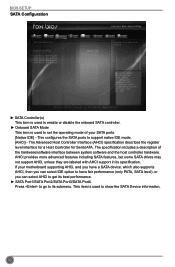
... host controller hardware. BIOS SETUP SATA Configuration Main F-center Advanced Boot Power Health Security Save&Exit SATA Configuration SATA Controller(s) Onboard SATA Mode ▶ SATA Port1: Not Present ▶ SATA Port2: Not Present ▶ SATA Port3: Not Present ▶ SATA Port4: Not Present [Enabled] [Native IDE] Enable or disable SATA Device → ←: Select Screen ↑ ↓: Select Item Enter: Select +/-: Change Opt. This configures the SATA ports to show the SATA Device information. 32 This item is used to support native IDE mode. [AHCI] - F1...
... host controller hardware. BIOS SETUP SATA Configuration Main F-center Advanced Boot Power Health Security Save&Exit SATA Configuration SATA Controller(s) Onboard SATA Mode ▶ SATA Port1: Not Present ▶ SATA Port2: Not Present ▶ SATA Port3: Not Present ▶ SATA Port4: Not Present [Enabled] [Native IDE] Enable or disable SATA Device → ←: Select Screen ↑ ↓: Select Item Enter: Select +/-: Change Opt. This configures the SATA ports to show the SATA Device information. 32 This item is used to support native IDE mode. [AHCI] - F1...
User manual
Page 41
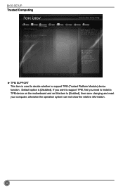
BIOS SETUP Trusted Computing Main F-center Advanced Boot TPM Configuration TPM SUPPORT Current TPM Status Information NO TPM Hardware Power Health [Disabled] Security Save&Exit Enables or Disables BIOS support O.S. Default option is required. → ←: Select Screen ↑ ↓: Select Item Enter: Select +/-: Change Opt. Copyright (C) 2012 American Megatrends, Inc. ► TPM SUPPORT This item is used to decide whether to [Enabled], then save changing and reset your computer, otherwise the operation...
BIOS SETUP Trusted Computing Main F-center Advanced Boot TPM Configuration TPM SUPPORT Current TPM Status Information NO TPM Hardware Power Health [Disabled] Security Save&Exit Enables or Disables BIOS support O.S. Default option is required. → ←: Select Screen ↑ ↓: Select Item Enter: Select +/-: Change Opt. Copyright (C) 2012 American Megatrends, Inc. ► TPM SUPPORT This item is used to decide whether to [Enabled], then save changing and reset your computer, otherwise the operation...

User manual
Page 43
BIOS SETUP Boot Main F-center Advanced Boot Boot Configuration Bootup Numlock State Quiet Boot Fast Boot Interrupt 19 Capture ▶ CSM parameters Set Boot Priority 1st Boot 2nd Boot 3rd Boot 4th Boot 5th Boot 6th Boot 7th Boot 8th Boot ▶ USB HardDisk Drive BBS Priorities ▶ USB KEY Drive BBS Priorities ▶ UEFI Boot Drive BBS Prioriies Power Health [On] [Enabled] [Disabled] [Enabled] [Hard Disk] [CD/DVD] [USB Floppy] [USB CD/DVD] [USB Hard Disk] [USB KEY] [Network] [UEFI] Security Save&Exit Select the ...
BIOS SETUP Boot Main F-center Advanced Boot Boot Configuration Bootup Numlock State Quiet Boot Fast Boot Interrupt 19 Capture ▶ CSM parameters Set Boot Priority 1st Boot 2nd Boot 3rd Boot 4th Boot 5th Boot 6th Boot 7th Boot 8th Boot ▶ USB HardDisk Drive BBS Priorities ▶ USB KEY Drive BBS Priorities ▶ UEFI Boot Drive BBS Prioriies Power Health [On] [Enabled] [Disabled] [Enabled] [Hard Disk] [CD/DVD] [USB Floppy] [USB CD/DVD] [USB Hard Disk] [USB KEY] [Network] [UEFI] Security Save&Exit Select the ...
User manual
Page 47
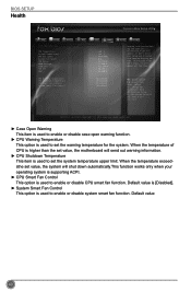
... option is used to set the system temperature upper limit. CPU Warning Temperature CPU Shutdowm Temperature CPU Smart Fan Control System Smart Fan Control [Disabled] [Disabled] [Disabled] [Disabled] → ←: Select Screen ↑ ↓: Select Item Enter: Select +/-: Change Opt. Default value 40 When the temperature of CPU is higher than the set value, the motherboard will shut down automatically.This function works only when your operating system is supporting ACPI. ► CPU Smart Fan Control This option is used to enable or disable case open chassis, Instruction...
... option is used to set the system temperature upper limit. CPU Warning Temperature CPU Shutdowm Temperature CPU Smart Fan Control System Smart Fan Control [Disabled] [Disabled] [Disabled] [Disabled] → ←: Select Screen ↑ ↓: Select Item Enter: Select +/-: Change Opt. Default value 40 When the temperature of CPU is higher than the set value, the motherboard will shut down automatically.This function works only when your operating system is supporting ACPI. ► CPU Smart Fan Control This option is used to enable or disable case open chassis, Instruction...
User manual
Page 51
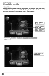
After that, you can click "One Click Setup" and then choose the items you want to install, or you want to install it first. Manual Installation Step by Step Automatic Installation by One Click Drop to System Tray Exit the program Visit Foxconn's Show Utilities Show Drivers Browse CD View User's Manual website Choose the items you can click on each individual driver to Install 44 You must click "Intel Chipset Driver" to install all the drivers for your system. CD INSTRUCTION 4-1 Install driver and utility 1. Install Driver Use these options to install it manually.
After that, you can click "One Click Setup" and then choose the items you want to install, or you want to install it first. Manual Installation Step by Step Automatic Installation by One Click Drop to System Tray Exit the program Visit Foxconn's Show Utilities Show Drivers Browse CD View User's Manual website Choose the items you can click on each individual driver to Install 44 You must click "Intel Chipset Driver" to install all the drivers for your system. CD INSTRUCTION 4-1 Install driver and utility 1. Install Driver Use these options to install it manually.


