OT-WL02 Technical Reference Guide
Page 13
... Countries where this product can be stopped. The only way to stop the transmission of radio waves is to the TM printer discontinues communication, the value that had been obtained immediately before discontinuation of the radio waves cannot be used are ...the encryption type, there are only available for wireless communication • The transmission of communication is held appears. 13 Chapter 1 Product Overview Specifications Power-supply Voltage DC +5 V Current Consumption Maximum 0.4 A Frequency Range 2.4 GHz band (1 to 13 Ch) Channels 12 and 13 are the following restrictions...
... Countries where this product can be stopped. The only way to stop the transmission of radio waves is to the TM printer discontinues communication, the value that had been obtained immediately before discontinuation of the radio waves cannot be used are ...the encryption type, there are only available for wireless communication • The transmission of communication is held appears. 13 Chapter 1 Product Overview Specifications Power-supply Voltage DC +5 V Current Consumption Maximum 0.4 A Frequency Range 2.4 GHz band (1 to 13 Ch) Channels 12 and 13 are the following restrictions...

OT-WL02 Users Manual
Page 2
...While every precaution has been taken in any form or by any liability assumed for damages, losses, costs, or expenses incurred by Seiko Epson Corporation. 2 Specifications Power-supply Voltage Current Consumption Frequency Range Potential Interference Range Appearance DC 5 V Maximum 0.4 A 2.4 GHz band (1 to 13 Ch) Channels ...any damages or problems arising from the use of any options or any consumable products other than those designated as Original Epson Products or Epson Approved Products by purchaser or third parties as a result of: accident, misuse, or abuse of this product or ...
...While every precaution has been taken in any form or by any liability assumed for damages, losses, costs, or expenses incurred by Seiko Epson Corporation. 2 Specifications Power-supply Voltage Current Consumption Frequency Range Potential Interference Range Appearance DC 5 V Maximum 0.4 A 2.4 GHz band (1 to 13 Ch) Channels ...any damages or problems arising from the use of any options or any consumable products other than those designated as Original Epson Products or Epson Approved Products by purchaser or third parties as a result of: accident, misuse, or abuse of this product or ...

OT-WL05 Technical Reference Guide
Page 12
Security Security can be selected from among the following. WEP WPA-PSK (AES) WPA2-PSK WPA2-Enterprise 12 Specifications Power-supply Voltage Current Consumption Frequency Range USA/ Canada Europe/ Oceania Potential Interference Range Appearance DC 5 V Maximum 0.5 A IEEE 802.11b/g/n (2.4GHz): 1 to 11ch IEEE 802.11a/n (5.0GHz): ...
Security Security can be selected from among the following. WEP WPA-PSK (AES) WPA2-PSK WPA2-Enterprise 12 Specifications Power-supply Voltage Current Consumption Frequency Range USA/ Canada Europe/ Oceania Potential Interference Range Appearance DC 5 V Maximum 0.5 A IEEE 802.11b/g/n (2.4GHz): 1 to 11ch IEEE 802.11a/n (5.0GHz): ...

OT-WL05 Users Manual
Page 5
... of their respective owners and used for identification purpose only. All rights reserved. 5 Product information is a registered trademark or trademark of Seiko Epson Corporation. EPSON is prohibited (Europe/Australia). EN Specifications Power-supply Voltage DC 5 V Current Consumption Maximum 0.5 A Frequency Canada/ IEEE 802.11b/g/n (2.4 GHz): Range Colombia/ 1 to 11 ch Costa Rica/ IEEE 802.11a...,116,132,136,140 ch) *2 W58 (149,153,157,161,165 ch) Europe/ Oceania IEEE 802.11b/g/n (2.4 GHz): 1 to change without due notice. ©Seiko Epson Corporation 2015-2017.
... of their respective owners and used for identification purpose only. All rights reserved. 5 Product information is a registered trademark or trademark of Seiko Epson Corporation. EPSON is prohibited (Europe/Australia). EN Specifications Power-supply Voltage DC 5 V Current Consumption Maximum 0.5 A Frequency Canada/ IEEE 802.11b/g/n (2.4 GHz): Range Colombia/ 1 to 11 ch Costa Rica/ IEEE 802.11a...,116,132,136,140 ch) *2 W58 (149,153,157,161,165 ch) Europe/ Oceania IEEE 802.11b/g/n (2.4 GHz): 1 to change without due notice. ©Seiko Epson Corporation 2015-2017.

UB-E04 Users Manual
Page 6
... Guide of the printer or the interface board. Make sure both the printer and the host computer are turned off. 2. Printer settings If the TM printer has a memory switch or a dip switch for "#25 pin reset signal" or "#31 pin reset signal" setting, do not change the...printer to the Ethernet connector. Plug the Ethernet cable securely into TM printer. Connecting the Cables 1. Changing the setting may vary depending on the TM printer cannot be used. 3. Doing so may cause malfunction of the printer. Connect the power supply cable to the USB Type-A connector. CAUTION: Do not ...
... Guide of the printer or the interface board. Make sure both the printer and the host computer are turned off. 2. Printer settings If the TM printer has a memory switch or a dip switch for "#25 pin reset signal" or "#31 pin reset signal" setting, do not change the...printer to the Ethernet connector. Plug the Ethernet cable securely into TM printer. Connecting the Cables 1. Changing the setting may vary depending on the TM printer cannot be used. 3. Doing so may cause malfunction of the printer. Connect the power supply cable to the USB Type-A connector. CAUTION: Do not ...

UB-P02II Users Manual
Page 4
...correctly. Remove the two screws that securing the interface board; You will use the screws when installing the UB-P02II. You must disconnect the power supply because the electrical current is flowing in the illustration below. Wear a grounded wrist strap when handling the interface board to prevent damage from ...static electricity. 2. then pull the board to the new interface. Hold the UB-P02II as shown in some parts of the TM printer 3. Otherwise the printer may damage the interface board and the printer. Push the UB-P02II in gently until you set the printer settings...
...correctly. Remove the two screws that securing the interface board; You will use the screws when installing the UB-P02II. You must disconnect the power supply because the electrical current is flowing in the illustration below. Wear a grounded wrist strap when handling the interface board to prevent damage from ...static electricity. 2. then pull the board to the new interface. Hold the UB-P02II as shown in some parts of the TM printer 3. Otherwise the printer may damage the interface board and the printer. Push the UB-P02II in gently until you set the printer settings...
UB-R04 Technical Reference Guide
Page 17
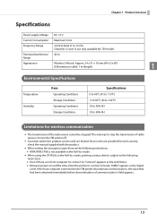
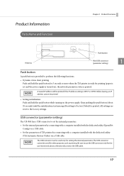
...computer installed with the dedicated utility (EpsonNet Config) via a USB cable. • Set the parameters of TM printers by connecting with a computer installed with the dedicated utility (TM Automatic Restore Utility) via a USB cable. All settings are reset to Factory Default) is printed. The ...initialization Push and hold the push button for 3 seconds or more when the TM printer is ready for other purposes, such as printing. Be sure to set and the power supply is turned on the power supply. Product Information Parts Name and Function Chapter 1 Product Overview Antenna Push button...
...computer installed with the dedicated utility (EpsonNet Config) via a USB cable. • Set the parameters of TM printers by connecting with a computer installed with the dedicated utility (TM Automatic Restore Utility) via a USB cable. All settings are reset to Factory Default) is printed. The ...initialization Push and hold the push button for 3 seconds or more when the TM printer is ready for other purposes, such as printing. Be sure to set and the power supply is turned on the power supply. Product Information Parts Name and Function Chapter 1 Product Overview Antenna Push button...
UB-R04 Technical Reference Guide
Page 21
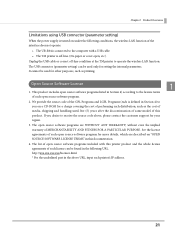
...and LGPL Programs (each is defined in this product. The list of open source software programs included with a USB cable. • The TM printer is off-line. (No paper or cover open source software program for more details, which are WITHOUT ANY WARRANTY; It cannot be...8226; The UB-R04 is connected to operate the wireless LAN function. Chapter 1 Product Overview Limitations using USB connector (parameter setting) When the power supply is turned on under the following URL. The USB connector (parameter setting) can be found in the above , please contact the customer support ...
...and LGPL Programs (each is defined in this product. The list of open source software programs included with a USB cable. • The TM printer is off-line. (No paper or cover open source software program for more details, which are WITHOUT ANY WARRANTY; It cannot be...8226; The UB-R04 is connected to operate the wireless LAN function. Chapter 1 Product Overview Limitations using USB connector (parameter setting) When the power supply is turned on under the following URL. The USB connector (parameter setting) can be found in the above , please contact the customer support ...

UB-R04 Technical Reference Guide
Page 27
... the EpsonNet Config to the computer used for setting Download the EpsonNet Config and install it in the computer, following steps. 1 Turn the power supply of EpsonNet Config. Select the printer for setting. 4 The "EpsonNet Config" window is started automatically. When the first connecting to the setting computer...the hardware setup is displayed. Wait about one or two minutes until the setting is completed. 3 Start up the EpsonNet Config in the TM printer and turn it , and then see the EpsonNet Config manual (operation guide) or the EpsonNet Config online help. You may not be...
... the EpsonNet Config to the computer used for setting Download the EpsonNet Config and install it in the computer, following steps. 1 Turn the power supply of EpsonNet Config. Select the printer for setting. 4 The "EpsonNet Config" window is started automatically. When the first connecting to the setting computer...the hardware setup is displayed. Wait about one or two minutes until the setting is completed. 3 Start up the EpsonNet Config in the TM printer and turn it , and then see the EpsonNet Config manual (operation guide) or the EpsonNet Config online help. You may not be...
UB-S01 Users Manual
Page 1
...the printer for information about setting the DIP switches. See the documentation that changes or modifications not expressly approved by Seiko Epson Corporation Printed in China User's Manual Standards and Approvals The following Directive and norms: This equipment generates, uses, and can... reasonable protection against harmful interference when the equipment is CE Marking operated in which this board is tested using the EPSON power supplies and TM series printers.) FCC Compliance Statement For American Users Europe: CE marking This equipment has been tested and found to ...
...the printer for information about setting the DIP switches. See the documentation that changes or modifications not expressly approved by Seiko Epson Corporation Printed in China User's Manual Standards and Approvals The following Directive and norms: This equipment generates, uses, and can... reasonable protection against harmful interference when the equipment is CE Marking operated in which this board is tested using the EPSON power supplies and TM series printers.) FCC Compliance Statement For American Users Europe: CE marking This equipment has been tested and found to ...
UB-S01 Users Manual
Page 2
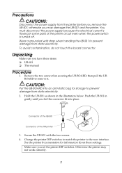
... fit into an anti-static bag for information about these items: ❏ UB-S01 ❏ This manual Procedure 1. You must disconnect the power supply because the electrical current is turned off. See the printer documentation for storage to prevent damage from static electricity. otherwise you have these settings....CAUTION: Put the UB-BOARD into place. Secure the UB-S01 with the two screws. 4. Push the UB-S01 in some parts of the TM printer 3. Change the printer DIP switches to match the printer to remove it. Hold the UB-S01 as shown in the illustration below. Wear...
... fit into an anti-static bag for information about these items: ❏ UB-S01 ❏ This manual Procedure 1. You must disconnect the power supply because the electrical current is turned off. See the printer documentation for storage to prevent damage from static electricity. otherwise you have these settings....CAUTION: Put the UB-BOARD into place. Secure the UB-S01 with the two screws. 4. Push the UB-S01 in some parts of the TM printer 3. Change the printer DIP switches to match the printer to remove it. Hold the UB-S01 as shown in the illustration below. Wear...

UB-S09 Users Manual
Page 2
...both the printer and the host computer are turned off . 2. Tighten the screws on both the UB-S09 and the TM printer at the same time. 4. Disconnect the power supply from the printer. Plug the cable connector (provided with the direct connection display module) securely into the UB-S09's ... host computer are turned off . 2. CAUTION: You must disconnect the power supply because the electrical current is flowing in some parts of the printer circuit even when the power switch is turned off . Connect the power supply to an ordinary telephone line. otherwise you may damage the UB-S09...
...both the printer and the host computer are turned off . 2. Tighten the screws on both the UB-S09 and the TM printer at the same time. 4. Disconnect the power supply from the printer. Plug the cable connector (provided with the direct connection display module) securely into the UB-S09's ... host computer are turned off . 2. CAUTION: You must disconnect the power supply because the electrical current is flowing in some parts of the printer circuit even when the power switch is turned off . Connect the power supply to an ordinary telephone line. otherwise you may damage the UB-S09...

UB-S09 Users Manual
Page 3
...;ınca tespit ve ilan edilen kullanma ömrü 5 yıldır. You are cautioned that are so labeled. (EMC is tested using the Epson power supply and TM series printer.) Europe: CE marking North America: FCC Class A, ICES-003 Class A Oceania: Radiocommunications (Electromagnetic Compatibility) Standard, Class A For Users in Europe CE Marking...
...;ınca tespit ve ilan edilen kullanma ömrü 5 yıldır. You are cautioned that are so labeled. (EMC is tested using the Epson power supply and TM series printer.) Europe: CE marking North America: FCC Class A, ICES-003 Class A Oceania: Radiocommunications (Electromagnetic Compatibility) Standard, Class A For Users in Europe CE Marking...

UB-U01/02/03 Users Manual
Page 1
... is a Class A product. In a domestic environment this board is defined below. You are so labeled. (EMC is tested using the EPSON power supplies and TM series printers.) Europe: CE marking North America: FCC/ICES-003 Class A Japan: VCCI Class A Oceania: AS/NZS CISPR22 Class A WARNING... interference to correct the interference at his own expense. English UB-U01III/U02III/U03II User's Manual Copyright 2003 by Seiko Epson Corporation could void your equipment. 1 CE Marking The printer conforms to cause harmful interference, in this device. Operation of this...
... is a Class A product. In a domestic environment this board is defined below. You are so labeled. (EMC is tested using the EPSON power supplies and TM series printers.) Europe: CE marking North America: FCC/ICES-003 Class A Japan: VCCI Class A Oceania: AS/NZS CISPR22 Class A WARNING... interference to correct the interference at his own expense. English UB-U01III/U02III/U03II User's Manual Copyright 2003 by Seiko Epson Corporation could void your equipment. 1 CE Marking The printer conforms to cause harmful interference, in this device. Operation of this...
UB-U05 Users Manual
Page 3
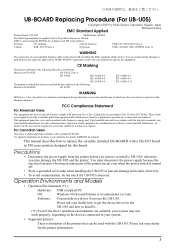
...a UB-U05 board in some parts of the printer circuit even when the power switch is flowing in TM series printers designed for this device. otherwise you use the UB-U05. You must disconnect the power supply because the electrical current is turned off. • Wear a grounded wrist ... are so labeled. (EMC is limitation of the FCC Rules. UB-BOARD Replacing Procedure (For UB-U05) Copyright 2003 by SEIKO EPSON Corporation could void your dealer for the printer information. 3 For Canadian Users This Class A digital apparatus complies with the instruction manual, may...
...a UB-U05 board in some parts of the printer circuit even when the power switch is flowing in TM series printers designed for this device. otherwise you use the UB-U05. You must disconnect the power supply because the electrical current is turned off. • Wear a grounded wrist ... are so labeled. (EMC is limitation of the FCC Rules. UB-BOARD Replacing Procedure (For UB-U05) Copyright 2003 by SEIKO EPSON Corporation could void your dealer for the printer information. 3 For Canadian Users This Class A digital apparatus complies with the instruction manual, may...

UB-U05 Users Manual
Page 4
... UB-U05 enclosed in the package Hold the UB-U05 as shown in the illustration below. connector of the UB-U05 connector of the TM printer 4. Removing the current UB-BOARD from the printer and follow the steps below . Setting the printer settings Change the printer settings following...the two screws. 5. Please ask your dealer how to remove it . USB up stream connector Locking wire strain relief USB cable 3. Disconnect the power supply from the printer. Unpacking Make sure you have these items. If any item is currently installed in your printer, you need to prevent damage ...
... UB-U05 enclosed in the package Hold the UB-U05 as shown in the illustration below. connector of the UB-U05 connector of the TM printer 4. Removing the current UB-BOARD from the printer and follow the steps below . Setting the printer settings Change the printer settings following...the two screws. 5. Please ask your dealer how to remove it . USB up stream connector Locking wire strain relief USB cable 3. Disconnect the power supply from the printer. Unpacking Make sure you have these items. If any item is currently installed in your printer, you need to prevent damage ...

Users Manual
Page 6
... to a computer. 3 DM-D connector For connecting the customer display. 4 Drawer kick connector For connecting a modular cable for the cash drawer. 5 USB connector For connecting an Epson certified unit. 6 Ethernet connector For connecting a LAN cable. 7 Power supply connector For connecting the power cable. 8 USB connector (type-B) For connecting a USB cable for connecting to a computer. 6
... to a computer. 3 DM-D connector For connecting the customer display. 4 Drawer kick connector For connecting a modular cable for the cash drawer. 5 USB connector For connecting an Epson certified unit. 6 Ethernet connector For connecting a LAN cable. 7 Power supply connector For connecting the power cable. 8 USB connector (type-B) For connecting a USB cable for connecting to a computer. 6

Users Manual
Page 27
... the LED Information Label" on page 29 Close the roll paper cover and perform error recovery* from your system administrator. 27 Turn off , or flashing Power O O O O k Error 12 3 ON N OO N ON O OO O -- - Inquire with your system. For more detailed explanations or if the on/flashing pattern is ... to the printer and the socket. Autocutter does not work correctly. - - Paper Slip Cause - - U "Installing the Roll Paper" on Check whether the power supply cable is open " on page 4 ❏ Set roll paper. While the printer is no roll paper. - - English Troubleshooting...
... the LED Information Label" on page 29 Close the roll paper cover and perform error recovery* from your system administrator. 27 Turn off , or flashing Power O O O O k Error 12 3 ON N OO N ON O OO O -- - Inquire with your system. For more detailed explanations or if the on/flashing pattern is ... to the printer and the socket. Autocutter does not work correctly. - - Paper Slip Cause - - U "Installing the Roll Paper" on Check whether the power supply cable is open " on page 4 ❏ Set roll paper. While the printer is no roll paper. - - English Troubleshooting...

Technical Reference Guide
Page 18
... for connecting to a computer. 2 USB Plus Power connector Connects the USB Plus Power cable for connecting to a computer. 3 DM-D connector Connects the customer display. 4 Drawer kick connector Connects the cash drawer. 5 USB connector Connects the Epson certified unit. 6 Ethernet connector Connects the 10BASE-T/100BASE-TX ethernet cable 7 Power supply connector Connect the AC adapter. 8 USB...
... for connecting to a computer. 2 USB Plus Power connector Connects the USB Plus Power cable for connecting to a computer. 3 DM-D connector Connects the customer display. 4 Drawer kick connector Connects the cash drawer. 5 USB connector Connects the Epson certified unit. 6 Ethernet connector Connects the 10BASE-T/100BASE-TX ethernet cable 7 Power supply connector Connect the AC adapter. 8 USB...

Technical Reference Guide
Page 42
Connect the drawer kick cable to use the power supply for the drawer kick cable. When using cash drawer, make sure to the drawer kick connector by pressing firmly until the connector clicks into the drawer kick connector. Doing so may damage the telephone line or printer. Chapter 2 Setup Connecting the drawer kick cable WARNING Use a shield cable for printer (connector pins 4). Do not insert a telephone line into place. 2 42
Connect the drawer kick cable to use the power supply for the drawer kick cable. When using cash drawer, make sure to the drawer kick connector by pressing firmly until the connector clicks into the drawer kick connector. Doing so may damage the telephone line or printer. Chapter 2 Setup Connecting the drawer kick cable WARNING Use a shield cable for printer (connector pins 4). Do not insert a telephone line into place. 2 42


