
UB-E04 Users Manual
Page 6
...USB Type-A connector. Changing the setting may vary depending on the TM printer cannot be used. 3. Doing so may cause malfunction of the printer. Plug the Ethernet cable securely into TM printer. Printer settings If the TM printer has a memory switch or a dip switch for "#25 pin reset signal"... or "#31 pin reset signal" setting, do not change the setting from or install the interface board into the UB-E04...
...USB Type-A connector. Changing the setting may vary depending on the TM printer cannot be used. 3. Doing so may cause malfunction of the printer. Plug the Ethernet cable securely into TM printer. Printer settings If the TM printer has a memory switch or a dip switch for "#25 pin reset signal"... or "#31 pin reset signal" setting, do not change the setting from or install the interface board into the UB-E04...
UB-R04 Technical Reference Guide
Page 24
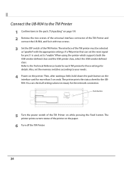
... of the TM printer must be selected as "parallel" with two screws. 3 Set the DIP switch of the TM Printer. Refer to "enable."When using the printer which supports both the USB vendor-defined class and the USB printer class, select the USB vendor-defined class. You can set the reset signal... for pin 31 is used, set the memory switches according to your ...
... of the TM printer must be selected as "parallel" with two screws. 3 Set the DIP switch of the TM Printer. Refer to "enable."When using the printer which supports both the USB vendor-defined class and the USB printer class, select the USB vendor-defined class. You can set the reset signal... for pin 31 is used, set the memory switches according to your ...
UB-R04 Users Manual
Page 2
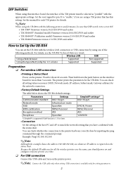
...AES Passphrase EpsonNet SimpleAP settings* 802.11b/g/n EPSON_Printer WPA2-Personal AES 12345678 *) SimpleAP is supported if Soft Version is 1.10 or later. • Connection Set the setting of the host PC and AP to match the network setting that DIP switch 1-8 is set to ON. • TM-T88V Firmware version 30....21 ESC/POS and earlier • TM-H6000IV (Standard model) Firmware version 20.04 ESC/POS and...
...AES Passphrase EpsonNet SimpleAP settings* 802.11b/g/n EPSON_Printer WPA2-Personal AES 12345678 *) SimpleAP is supported if Soft Version is 1.10 or later. • Connection Set the setting of the host PC and AP to match the network setting that DIP switch 1-8 is set to ON. • TM-T88V Firmware version 30....21 ESC/POS and earlier • TM-H6000IV (Standard model) Firmware version 20.04 ESC/POS and...
UB-S01 Users Manual
Page 1
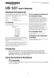
... Directive 2004/108/EC used in accordance with the printer for this equipment in a residential area is tested using the EPSON power supplies and TM series printers.) FCC Compliance Statement For American Users Europe: CE marking This equipment has been tested and found to operate ... will invalidate the EMC standards of this board. Introduction This manual describes how to replace the UB-S01 on TM series printers designed for information about setting the DIP switches. These products conform to the following standards are so labeled. (EMC is likely to radio EN 55024 IEC...
... Directive 2004/108/EC used in accordance with the printer for this equipment in a residential area is tested using the EPSON power supplies and TM series printers.) FCC Compliance Statement For American Users Europe: CE marking This equipment has been tested and found to operate ... will invalidate the EMC standards of this board. Introduction This manual describes how to replace the UB-S01 on TM series printers designed for information about setting the DIP switches. These products conform to the following standards are so labeled. (EMC is likely to radio EN 55024 IEC...
UB-S01 Users Manual
Page 2
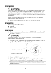
.... Connector of the UB-S01 Connector of the printer circuit even when the power switch is turned off. Otherwise the printer may damage the UB-S01 and the printer. otherwise you set the printer DIP switches. Make sure you may not work correctly. 2 CAUTION: Put the UB-BOARD into... place. To avoid contamination, do not touch the board connector. Hold the UB-S01 as shown in some parts of the TM printer 3. Change the printer DIP switches to match the...
.... Connector of the UB-S01 Connector of the printer circuit even when the power switch is turned off. Otherwise the printer may damage the UB-S01 and the printer. otherwise you set the printer DIP switches. Make sure you may not work correctly. 2 CAUTION: Put the UB-BOARD into... place. To avoid contamination, do not touch the board connector. Hold the UB-S01 as shown in some parts of the TM printer 3. Change the printer DIP switches to match the...

Technical Reference Guide
Page 8
... ■ Test Printing ...52 ■ Attaching the Power Switch Cover 53 ■ Applying the LED Information Label 54 ■ RTC Settings ...56 ■ Adjusting the Paper Roll Near-End Sensor 57 ■ Changing the Paper Width 58 Advanced Usage 59 ■ Setting the DIP Switches...59 Setting Procedure ...59 When a Serial Interface is Connected ...60 When...
... ■ Test Printing ...52 ■ Attaching the Power Switch Cover 53 ■ Applying the LED Information Label 54 ■ RTC Settings ...56 ■ Adjusting the Paper Roll Near-End Sensor 57 ■ Changing the Paper Width 58 Advanced Usage 59 ■ Setting the DIP Switches...59 Setting Procedure ...59 When a Serial Interface is Connected ...60 When...

Technical Reference Guide
Page 11
... Characteristics...129 DIP Switches...129 Printer Status ...129 Logo Registration...129 Driver Compatibility...129 USB Low Power Consumption Mode ...129 Maintenance Counter...129 Overall Dimensions ...130 ■ Additional Functions and Functional Improvements 131 Print Speed ...131 Interface...131 SimpleAP Function ...131 NFC ...131 Epson TM Utility for iOS/Android ...131 Software Settings...132 TM-Intelligent function...
... Characteristics...129 DIP Switches...129 Printer Status ...129 Logo Registration...129 Driver Compatibility...129 USB Low Power Consumption Mode ...129 Maintenance Counter...129 Overall Dimensions ...130 ■ Additional Functions and Functional Improvements 131 Print Speed ...131 Interface...131 SimpleAP Function ...131 NFC ...131 Epson TM Utility for iOS/Android ...131 Software Settings...132 TM-Intelligent function...

Technical Reference Guide
Page 43
For details, refer to an ordinary telephone line. 2 43 Do not connect these connectors to DM-D110/DM-D210 Technical Reference Guide. When connecting a customer display, set DIP switch 2-2 on page 59. The printer uses modular connectors specifically designed for the cash drawer. See "Setting the DIP Switches" on the printer to ON. Chapter 2 Setup Installing the Customer Display A customer display and DP-502 (customer display fixing plate) can be installed.
For details, refer to an ordinary telephone line. 2 43 Do not connect these connectors to DM-D110/DM-D210 Technical Reference Guide. When connecting a customer display, set DIP switch 2-2 on page 59. The printer uses modular connectors specifically designed for the cash drawer. See "Setting the DIP Switches" on the printer to ON. Chapter 2 Setup Installing the Customer Display A customer display and DP-502 (customer display fixing plate) can be installed.

Technical Reference Guide
Page 59
... this printer, you can make various settings with the cover open the DIP switch cover, be sure to remove the DIP switch cover from the base of a tool, such as a small screwdriver. 4 Replace the DIP switch cover, and screw it in place. 59 The DIP switches are changed after adjusting the DIP switch. DSW1 (DIP switch 1) DSW2 (DIP switch 2) 3 Set the DIP switches, using the tip of the...
... this printer, you can make various settings with the cover open the DIP switch cover, be sure to remove the DIP switch cover from the base of a tool, such as a small screwdriver. 4 Replace the DIP switch cover, and screw it in place. 59 The DIP switches are changed after adjusting the DIP switch. DSW1 (DIP switch 1) DSW2 (DIP switch 2) 3 Set the DIP switches, using the tip of the...

Technical Reference Guide
Page 60
... ON OFF ON 3 ON OFF 38400 * OFF OFF bps: bits per second The setting value of the communication conditions of the serial interface set in the software settings is Connected DIP Switch Bank 1 SW Function 1-1 Data reception error 1-2 Receive buffer capacity 1-3 Handshaking 1-4 Word length 1-5 ... "?" 45 bytes 4 KB XON/XOFF 7 bits DTR/DSR 8 bits Yes No Even Odd See the "Transmission Speed (DIP Switches 1-7/1-8)" table below. The setting value can be specified as 2400, 4800, 9600, 19200, 38400, 57600, and 115200. Chapter 3 Advanced Usage When a Serial Interface...
... ON OFF ON 3 ON OFF 38400 * OFF OFF bps: bits per second The setting value of the communication conditions of the serial interface set in the software settings is Connected DIP Switch Bank 1 SW Function 1-1 Data reception error 1-2 Receive buffer capacity 1-3 Handshaking 1-4 Word length 1-5 ... "?" 45 bytes 4 KB XON/XOFF 7 bits DTR/DSR 8 bits Yes No Even Odd See the "Transmission Speed (DIP Switches 1-7/1-8)" table below. The setting value can be specified as 2400, 4800, 9600, 19200, 38400, 57600, and 115200. Chapter 3 Advanced Usage When a Serial Interface...

Technical Reference Guide
Page 61
... OFF OFF 3 2-3 Selects print density 2-4 See "Selecting the Print Density (DIP Switches 2-3/2-4)" OFF on page 62. 2-5 Reserved - - OFF 2-6 Reserved (Do not change settings) Fixed to OFF OFF 2-7 Reserved (Do not change settings) Fixed to OFF OFF Fixed to OFF * OFF Set for USB Plus Power I/F and Bluetooth I/F. 61 Chapter 3 Advanced Usage When Another...
... OFF OFF 3 2-3 Selects print density 2-4 See "Selecting the Print Density (DIP Switches 2-3/2-4)" OFF on page 62. 2-5 Reserved - - OFF 2-6 Reserved (Do not change settings) Fixed to OFF OFF 2-7 Reserved (Do not change settings) Fixed to OFF OFF Fixed to OFF * OFF Set for USB Plus Power I/F and Bluetooth I/F. 61 Chapter 3 Advanced Usage When Another...

Technical Reference Guide
Page 62
... turned on (including resetting with the Feed button. When an error has occurred. Chapter 3 Advanced Usage Selecting the Print Density (DIP Switches 2-3/2-4) Function Do not set Print density (standard) Print density (medium) Print density (dark) SW 2-3 ON OFF ON OFF SW 2-4 ON OFF OFF ...ON If the print density is set with DIP switches (2-3/2-4) or the software settings. (See "Software Settings" on page 63.) Selecting the BUSY Status With DIP switch 2-1, you can select conditions for the paper Feed button to be set to "Medium" or "Dark" level, print speed may ...
... turned on (including resetting with the Feed button. When an error has occurred. Chapter 3 Advanced Usage Selecting the Print Density (DIP Switches 2-3/2-4) Function Do not set Print density (standard) Print density (medium) Print density (dark) SW 2-3 ON OFF ON OFF SW 2-4 ON OFF OFF ...ON If the print density is set with DIP switches (2-3/2-4) or the software settings. (See "Software Settings" on page 63.) Selecting the BUSY Status With DIP switch 2-1, you can select conditions for the paper Feed button to be set to "Medium" or "Dark" level, print speed may ...

Technical Reference Guide
Page 66
... the paper width from 80 mm to 58 mm, you select the 58 mm paper width. (See "Changing the Paper Width" on the DIP switch settings The specified original paper types and recommended print densities are as indicated below a room temperature of 15°C, the speed drops to less than ...200 mm/sec. When setting the print speed to level 14, use customized values to 130% (5% increment) Default setting: Depends on page 58.) Because some parts of the following. Chapter 3 Advanced Usage NV graphics memory...
... the paper width from 80 mm to 58 mm, you select the 58 mm paper width. (See "Changing the Paper Width" on the DIP switch settings The specified original paper types and recommended print densities are as indicated below a room temperature of 15°C, the speed drops to less than ...200 mm/sec. When setting the print speed to level 14, use customized values to 130% (5% increment) Default setting: Depends on page 58.) Because some parts of the following. Chapter 3 Advanced Usage NV graphics memory...

Technical Reference Guide
Page 76
...printing starts.) After printing the current print status, a Continuing self-test guidance is printed, the printer initializes and switches to continue the self-test. Chapter 3 Advanced Usage Self-test Mode You can check the following items using the... number Interface information Customer display setting Built-in character fonts Automatic line feed setting Print density setting Usable device Recovery point information Maintenance information DIP switch settings Follow the steps below. 3 1 Make sure all...
...printing starts.) After printing the current print status, a Continuing self-test guidance is printed, the printer initializes and switches to continue the self-test. Chapter 3 Advanced Usage Self-test Mode You can check the following items using the... number Interface information Customer display setting Built-in character fonts Automatic line feed setting Print density setting Usable device Recovery point information Maintenance information DIP switch settings Follow the steps below. 3 1 Make sure all...

Technical Reference Guide
Page 113
...not connected. The printer driver and application set - The printer driver and application set - Set DIP switch 2-2 on the printer is "Serial interface only". Solution and reference Set the display's transmission speed to "All interfaces that can be used". DIP switch 2-2 on the printer to check operation.... drawer and the cable. See "Software Settings" on page 41. The cash drawer does not open Cause Solution and reference The cash drawer is not correct. The cash drawer specifications and Use the TM-H6000V Utility to ON. drawer port specifications are...
...not connected. The printer driver and application set - The printer driver and application set - Set DIP switch 2-2 on the printer is "Serial interface only". Solution and reference Set the display's transmission speed to "All interfaces that can be used". DIP switch 2-2 on the printer to check operation.... drawer and the cable. See "Software Settings" on page 41. The cash drawer does not open Cause Solution and reference The cash drawer is not correct. The cash drawer specifications and Use the TM-H6000V Utility to ON. drawer port specifications are...

Technical Reference Guide
Page 128
...for clearing the buffer in the same manner as those of the TM-H6000IV. Print Density Print density of the TM-H6000V is the same as for the TM-H6000IV by using the software setting mode or by using DIP switches 2-3 and 2-4. Specify the buffer-full conditions and conditions for ...the receive buffer of the TM-H6000V in the same manner as the TM-H6000IV. Printable Area The ...
...for clearing the buffer in the same manner as those of the TM-H6000IV. Print Density Print density of the TM-H6000V is the same as for the TM-H6000IV by using the software setting mode or by using DIP switches 2-3 and 2-4. Specify the buffer-full conditions and conditions for ...the receive buffer of the TM-H6000V in the same manner as the TM-H6000IV. Printable Area The ...

Technical Reference Guide
Page 129
DIP Switches The functional assignments of DIP switches for more details. See "Setting the DIP Switches" on the print duty. Printer Status The TM-H6000V goes to 350 mm/s, the amount of electricity consumed increases. If logo data registered for the TM-H6000IV. USB Low Power Consumption Mode With the TM-H6000V, you can replace the TM-H6000IV with a driver for the TM-H6000IV has...
DIP Switches The functional assignments of DIP switches for more details. See "Setting the DIP Switches" on the print duty. Printer Status The TM-H6000V goes to 350 mm/s, the amount of electricity consumed increases. If logo data registered for the TM-H6000IV. USB Low Power Consumption Mode With the TM-H6000V, you can replace the TM-H6000IV with a driver for the TM-H6000IV has...

Technical Reference Guide
Page 133
... or 5 GHz) Connects an optional Wireless LAN cable set to the USB connector. × 1 RS-232 × 1 Full-speed (12 Mbps) × 1 Bluetooth 3.0 (EDR supported) x1 Connect the customer display x1 Connect the cash drawer 4 KB/ 45 bytes Selectable by using the DIP switches. 12 KB For receipt: 12 KB For slip: 3 KB...
... or 5 GHz) Connects an optional Wireless LAN cable set to the USB connector. × 1 RS-232 × 1 Full-speed (12 Mbps) × 1 Bluetooth 3.0 (EDR supported) x1 Connect the customer display x1 Connect the cash drawer 4 KB/ 45 bytes Selectable by using the DIP switches. 12 KB For receipt: 12 KB For slip: 3 KB...

Technical Reference Guide
Page 140
... of 48 μm Paper must not be pasted to ensure optimal print quality and reliability, we recommend using the DIP switches and customized values. Specified original paper and recommended print density setting (DIP switches) Specified original paper Print density TF50KS-EY, TF60KS-EY, PD160R, PD190R, P220AGB-1 AF50KS-E, KT55FA, KT48FA Standard F5041(55), F5041(48...
... of 48 μm Paper must not be pasted to ensure optimal print quality and reliability, we recommend using the DIP switches and customized values. Specified original paper and recommended print density setting (DIP switches) Specified original paper Print density TF50KS-EY, TF60KS-EY, PD160R, PD190R, P220AGB-1 AF50KS-E, KT55FA, KT48FA Standard F5041(55), F5041(48...

Technical Reference Guide
Page 159
...Input Reception data 4 RTS Output Equivalent to DTR signal (pin 20) 6 DSR Input This signal indicates whether the host computer can receive data. Set BUSY conditions with DIP switch 1-6: Even Odd 1 or more . 7 SG - DSUB 25-pin (female) connector Functions of each connector pin Pin ...159 MARK indicates that the printer is BUSY. When you use this signal. The signal is always SPACE, except in the following with DIP switch 2-1. 2) When XON/XOFF control is selected, the signal indicates that the host computer cannot receive data. When DTR/DSR control is ...
...Input Reception data 4 RTS Output Equivalent to DTR signal (pin 20) 6 DSR Input This signal indicates whether the host computer can receive data. Set BUSY conditions with DIP switch 1-6: Even Odd 1 or more . 7 SG - DSUB 25-pin (female) connector Functions of each connector pin Pin ...159 MARK indicates that the printer is BUSY. When you use this signal. The signal is always SPACE, except in the following with DIP switch 2-1. 2) When XON/XOFF control is selected, the signal indicates that the host computer cannot receive data. When DTR/DSR control is ...


