
User Manual
Page 2
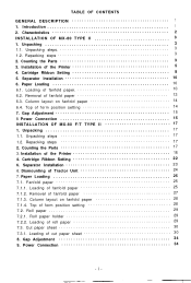
... Loading of form position setting 14 7. Installation of cut paper sheet 30 8. Loading of the Printer 18 4. Power Connection 34 -i- Unpacking steps 3 1.2. Counting the Parts 17 3. Cartridge Ribbon Setting 22 6. Roll paper holder 29 7.2.2. Loading of fanfold paper 13 6.3. Removal of roll paper 29 7.3. Gap Adjustment 15 8. Roll paper 29 7.2.1. Removal of Tractor Unit 24 7. Dismounting of fanfold paper 27 7.1.3. Gap Adjustment 34 9. Introduction 1 2. TABLE OF CONTENTS GENERAL DESCRIPTION 1 1. Installation of the Printer 5 4. Cartridge Ribbon Setting...
... Loading of form position setting 14 7. Installation of cut paper sheet 30 8. Loading of the Printer 18 4. Power Connection 34 -i- Unpacking steps 3 1.2. Counting the Parts 17 3. Cartridge Ribbon Setting 22 6. Roll paper holder 29 7.2.2. Loading of fanfold paper 13 6.3. Removal of roll paper 29 7.3. Gap Adjustment 15 8. Roll paper 29 7.2.1. Removal of Tractor Unit 24 7. Dismounting of fanfold paper 27 7.1.3. Gap Adjustment 34 9. Introduction 1 2. TABLE OF CONTENTS GENERAL DESCRIPTION 1 1. Installation of the Printer 5 4. Cartridge Ribbon Setting...
User Manual
Page 3
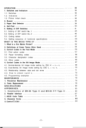
...-Test 4 0 5. Print action codes 57 3.2 Paper formatting codes 58 3.3. Preventive Maintenance 78 2. Indicators 37 1.3. Definitions of functional specifications 4 8 WHAT IS THE MX-80 TYPE II 52 1. H o w t o o b t a i n nI a n d n2 72 4.5. Coding tables 47 5.4. Control Codes in the Text Mode 56 3.1. Parts Replacement 78 SPECIFICATIONS 80 APPENDIXES 83 1. Setting sequence of Some Terms Often Used 54 3. What Is a Dot Matrix Printer 52 2. Relationship between data and dot wires 71 4 . 4 . Switches 36 1.2. Setting of MX-80 Type...
...-Test 4 0 5. Print action codes 57 3.2 Paper formatting codes 58 3.3. Preventive Maintenance 78 2. Indicators 37 1.3. Definitions of functional specifications 4 8 WHAT IS THE MX-80 TYPE II 52 1. H o w t o o b t a i n nI a n d n2 72 4.5. Coding tables 47 5.4. Control Codes in the Text Mode 56 3.1. Parts Replacement 78 SPECIFICATIONS 80 APPENDIXES 83 1. Setting sequence of Some Terms Often Used 54 3. What Is a Dot Matrix Printer 52 2. Relationship between data and dot wires 71 4 . 4 . Switches 36 1.2. Setting of MX-80 Type...
User Manual
Page 4
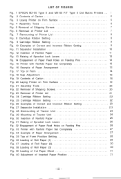
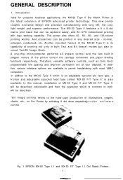
LIST OF FIGURES Fig. 1 EPSON MX-80 Type II and MX-80 F/T Type II Dot Matrix Printers ... 1 Fig. 2 Contents of Carton 4 Fig. 3 Laying Printer on Firm Surface 5 Fig. 4 Assembly Tools 6 Fig. 5 Removal of Shipping Screws 7 Fig. 6 Removal of Printer Lid 7 Fig. 7 Remounting of Printer Lid 8 Fig. 8 Cartridge Ribbon Setting 8 Fig. 9 Cartridge Ribbon Setting 9 Fig. 10 Examples of Correct and Incorrect Ribbon Setting 9 Fig. 11 Separator Installation 10 Fig. 12...
LIST OF FIGURES Fig. 1 EPSON MX-80 Type II and MX-80 F/T Type II Dot Matrix Printers ... 1 Fig. 2 Contents of Carton 4 Fig. 3 Laying Printer on Firm Surface 5 Fig. 4 Assembly Tools 6 Fig. 5 Removal of Shipping Screws 7 Fig. 6 Removal of Printer Lid 7 Fig. 7 Remounting of Printer Lid 8 Fig. 8 Cartridge Ribbon Setting 8 Fig. 9 Cartridge Ribbon Setting 9 Fig. 10 Examples of Correct and Incorrect Ribbon Setting 9 Fig. 11 Separator Installation 10 Fig. 12...
User Manual
Page 5
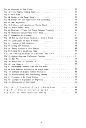
.... 41 Alignment of Side Edges 32 Fig. 42 Form Position Setting Mark 32 Fig. 43 Print Area 3 2 Fig. 44 Setting of Cut Paper Sheet 33 Fig. 45 Printer with Cut Paper Sheet Set Completely 33 Fig. 46 Gap Adjustment 35 Fig. 47 Switches and Indicators on Control Panel 36 Fig. 48 Printer Initial Check 38 Fig. 49 Flowchart of Paper Out Status Release Procedure 39 Fig. 50 Removing Manual Paper Feed Knob 41...
.... 41 Alignment of Side Edges 32 Fig. 42 Form Position Setting Mark 32 Fig. 43 Print Area 3 2 Fig. 44 Setting of Cut Paper Sheet 33 Fig. 45 Printer with Cut Paper Sheet Set Completely 33 Fig. 46 Gap Adjustment 35 Fig. 47 Switches and Indicators on Control Panel 36 Fig. 48 Printer Initial Check 38 Fig. 49 Flowchart of Paper Out Status Release Procedure 39 Fig. 50 Removing Manual Paper Feed Knob 41...
User Manual
Page 7
... operation which is an adjustable sprocket pin feed type, a friction and adjustable sprocket feed type called "MX-80 F/T Type II" is the latest extension of the printer control the carriage movement and paper feeding functions respectively. Therefore, versatile software controls, such as form feed, programmable line spacing and skip-over perforation are available to both Text and Bit Image* modes but also in any desired size - And characters can be printed...
... operation which is an adjustable sprocket pin feed type, a friction and adjustable sprocket feed type called "MX-80 F/T Type II" is the latest extension of the printer control the carriage movement and paper feeding functions respectively. Therefore, versatile software controls, such as form feed, programmable line spacing and skip-over perforation are available to both Text and Bit Image* modes but also in any desired size - And characters can be printed...
User Manual
Page 8
.... (4) High throughput by DIP switch setting or software. (7) Complete with initial setting to meet a wide range of Form - page length setting in horizontal direction) modes are selectable by bidirectional printing with versatile functions to meet various business applications (a) Top of applications from small business to -replace "throwaway" print head. The following is possible, with standard equipment including paper end detector, custom cartridge ribbon, etc. -2-
.... (4) High throughput by DIP switch setting or software. (7) Complete with initial setting to meet a wide range of Form - page length setting in horizontal direction) modes are selectable by bidirectional printing with versatile functions to meet various business applications (a) Top of applications from small business to -replace "throwaway" print head. The following is possible, with standard equipment including paper end detector, custom cartridge ribbon, etc. -2-
User Manual
Page 11
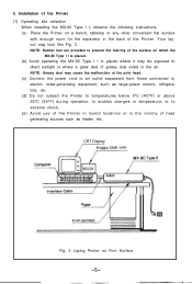
...°F) or above 35°C (95°F) during operation, to sudden changes in temperature, or to electric noise-generating equipment, such as heater, etc. Your layout may cause the malfunction of the print head. (c) Connect the power cord to an outlet separated from those connected to extreme shock. (e) Avoid use of the Printer in humid locations or in the air.
...°F) or above 35°C (95°F) during operation, to sudden changes in temperature, or to electric noise-generating equipment, such as heater, etc. Your layout may cause the malfunction of the print head. (c) Connect the power cord to an outlet separated from those connected to extreme shock. (e) Avoid use of the Printer in humid locations or in the air.
User Manual
Page 20
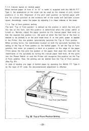
... column position at this point, turn the Power Switch on the fanfold paper. Namely, adjust the paper position by turning the manual paper feed knob. Now, the printing can be printed) is at a position on the edge of the paper 77mm above the first print line position of Form position, first enter (or preprint) a mark at the print head level. 6.3. Top of form position setting The term "Top of...
... column position at this point, turn the Power Switch on the fanfold paper. Namely, adjust the paper position by turning the manual paper feed knob. Now, the printing can be printed) is at a position on the edge of the paper 77mm above the first print line position of Form position, first enter (or preprint) a mark at the print head level. 6.3. Top of form position setting The term "Top of...
User Manual
Page 21
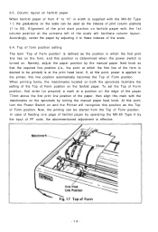
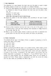
... a set of adjusting lever Set the lever to suit paper of a different thickness. (1) Move the head adjusting lever (located on the chassis at the rear of the Printer) forward or backward to operate the Printer. Gap Adjustment The adjustment of a gap between the head nose and the platen. (See Fig. 18.) Forward: To widen gap. Power Connection The EPSON MX-80 Type II Dot Matrix Printer is used to adjust the printing...
... a set of adjusting lever Set the lever to suit paper of a different thickness. (1) Move the head adjusting lever (located on the chassis at the rear of the Printer) forward or backward to operate the Printer. Gap Adjustment The adjustment of a gap between the head nose and the platen. (See Fig. 18.) Forward: To widen gap. Power Connection The EPSON MX-80 Type II Dot Matrix Printer is used to adjust the printing...
User Manual
Page 34
... at the print head level. Top of form position setting The term "Top of Form position" is defined as the position in width is supplied with the MX-80 F/T Type II, the graduations on the sprockets by adjusting it to the Printer, this point, turn the Power Switch on fanfold paper with the matchmarks on the scale can be printed) is turned on the...
... at the print head level. Top of form position setting The term "Top of Form position" is defined as the position in width is supplied with the MX-80 F/T Type II, the graduations on the sprockets by adjusting it to the Printer, this point, turn the Power Switch on fanfold paper with the matchmarks on the scale can be printed) is turned on the...
User Manual
Page 40
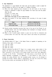
... the perforation. 9. Paper Single-leaf paper Carbon paper sheets Position of a gap between the head nose and the platen is used . Power Connection The EPSON MX-80 F/T Type I I . -34- After connection of the Printer to the proper power source and upon application of paper to adjust the gap between the head nose and the platen. (See Fig. 46.) Forward: To widen gap. Please obtain a replacement unit with the effects...
... the perforation. 9. Paper Single-leaf paper Carbon paper sheets Position of a gap between the head nose and the platen is used . Power Connection The EPSON MX-80 F/T Type I I . -34- After connection of the Printer to the proper power source and upon application of paper to adjust the gap between the head nose and the platen. (See Fig. 46.) Forward: To widen gap. Please obtain a replacement unit with the effects...
User Manual
Page 42
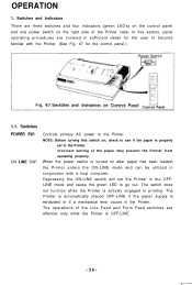
... the power switch is exhausted or if a mechanical error occurs in printing. The operations of the Line Feed and Form Feed switches are covered in the Printer. Switches POWER SW: ON LINE S W : Controls primary AC power to become familiar with a host computer. Depressing the ON-LINE switch will set the Printer in the OFFLINE mode and cause the green LED to see if the paper is OFF-LINE. -36- NOTE: Before turning this section, panel operating procedures...
... the power switch is exhausted or if a mechanical error occurs in printing. The operations of the Line Feed and Form Feed switches are covered in the Printer. Switches POWER SW: ON LINE S W : Controls primary AC power to become familiar with a host computer. Depressing the ON-LINE switch will set the Printer in the OFFLINE mode and cause the green LED to see if the paper is OFF-LINE. -36- NOTE: Before turning this section, panel operating procedures...
User Manual
Page 46
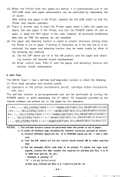
... turning the POWER switch on the paper by either of the following . (1) Print head operation and printing quality (2) Operation of the printer mechanisms (motor, cartridge ribbon mechanism, belt, etc.) The self-test function is to the last line is pre-programmed and can be performed by depressing the LF switch. To check all previously established data such as follows: a) Connect ACKNLG signal pin No. 10 to effect auto-line feed...
... turning the POWER switch on the paper by either of the following . (1) Print head operation and printing quality (2) Operation of the printer mechanisms (motor, cartridge ribbon mechanism, belt, etc.) The self-test function is to the last line is pre-programmed and can be performed by depressing the LF switch. To check all previously established data such as follows: a) Connect ACKNLG signal pin No. 10 to effect auto-line feed...

User Manual
Page 58
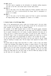
... EPSON MX-80 Type I I belongs to understand. The receive only printer means that it does not have a keyboard. -52- Control codes in the bit image mode This printer has two different print modes. You might be sorted to a computer or another is a dot matrix printer? 2. As a result, you probably do not understand the word "Bit Image." In this mode a printer prints alphabets, numbers and some terms often used...
... EPSON MX-80 Type I I belongs to understand. The receive only printer means that it does not have a keyboard. -52- Control codes in the bit image mode This printer has two different print modes. You might be sorted to a computer or another is a dot matrix printer? 2. As a result, you probably do not understand the word "Bit Image." In this mode a printer prints alphabets, numbers and some terms often used...
User Manual
Page 67
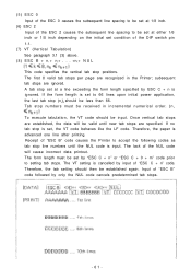
... switch pin 1-1. (7) VT (Vertical Tabulation) See paragraph 3.1 (3) above. ( 8 ) E S C B + n1 + nz+ . . . +nk+ N U L This code specifies the vertical tab stop set by "ESC C + n" or "ESC C + 0 + m" code prior to accept the following codes as tab stop line numbers until new tab stops are ignored. The lack of "ESC B" code followed by input of "ESC C + n" code. Therefore, the paper is cancelled by only the NUL code cancels predetermined tab stops...
... switch pin 1-1. (7) VT (Vertical Tabulation) See paragraph 3.1 (3) above. ( 8 ) E S C B + n1 + nz+ . . . +nk+ N U L This code specifies the vertical tab stop set by "ESC C + n" or "ESC C + 0 + m" code prior to accept the following codes as tab stop line numbers until new tab stops are ignored. The lack of "ESC B" code followed by input of "ESC C + n" code. Therefore, the paper is cancelled by only the NUL code cancels predetermined tab stops...
User Manual
Page 68
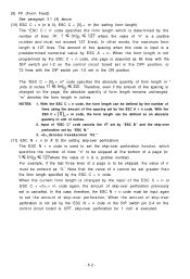
... DIP switch pin 2-4 on the page, the absolute quantity of form length remains unchanged. H denotes hexadecimal "00." (11) ESC N + n (n # 0) (for setting skip-over perforation) The ESC N + n code is used to set the skip-over perforation is not set by the ESC C + n code. The "ESC C + [0]H + m" code specifies the absolute quantity of form length in unit of line spacing set by the number of lines using the...
... DIP switch pin 2-4 on the page, the absolute quantity of form length remains unchanged. H denotes hexadecimal "00." (11) ESC N + n (n # 0) (for setting skip-over perforation) The ESC N + n code is used to set the skip-over perforation is not set by the ESC C + n code. The "ESC C + [0]H + m" code specifies the absolute quantity of form length in unit of line spacing set by the number of lines using the...
User Manual
Page 71
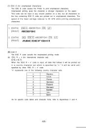
... set ) When the "ESC R + n" code is specified by other "ESC R + n" code. "n" represents one of the head carriage reduces to 40 CPS while printing emphasized characters. (8) ESC F The ESC F code cancels the emphasized printing mode. (9) ESC R + n (for international character set which is input, all characters on the paper. As for emphasized characters) The ESC E code causes the Printer to print emphasized characters. (7) ESC E (for specific code...
... set ) When the "ESC R + n" code is specified by other "ESC R + n" code. "n" represents one of the head carriage reduces to 40 CPS while printing emphasized characters. (8) ESC F The ESC F code cancels the emphasized printing mode. (9) ESC R + n (for international character set which is input, all characters on the paper. As for emphasized characters) The ESC E code causes the Printer to print emphasized characters. (7) ESC E (for specific code...
User Manual
Page 73
... there is used exclusively. To do that you to control any dot in the Text Mode causes the Printer's operation mode to be filled up with data up to draw and plot with the Bit Image mode will start printing bit image data from the first-in the text mode. (7) NUL (Null) The NUL code is input, and utilizes a raster scan technique that enables the printing of...
... there is used exclusively. To do that you to control any dot in the Text Mode causes the Printer's operation mode to be filled up with data up to draw and plot with the Bit Image mode will start printing bit image data from the first-in the text mode. (7) NUL (Null) The NUL code is input, and utilizes a raster scan technique that enables the printing of...
User Manual
Page 92
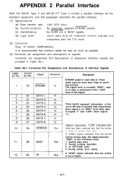
... parallel interface. (1) Specifications (a) Data transfer rate: 1000 CPS (min.) (b) Synchronization: By externally supplied STROBE pulses. (c) Handshaking: By ACKN LG or BUSY signals. (d) Logic level: Input data and all interface control signals are provided in the following cases: 1. The signal becomes "HIGH" in Table A2-1. In OFF-LINE state 4. During printing operation 3. Each signal is logical "I" and "LOW" when logical "0". Table...
... parallel interface. (1) Specifications (a) Data transfer rate: 1000 CPS (min.) (b) Synchronization: By externally supplied STROBE pulses. (c) Handshaking: By ACKN LG or BUSY signals. (d) Logic level: Input data and all interface control signals are provided in the following cases: 1. The signal becomes "HIGH" in Table A2-1. In OFF-LINE state 4. During printing operation 3. Each signal is logical "I" and "LOW" when logical "0". Table...
User Manual
Page 93
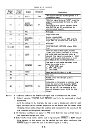
... on the Return side. Data transfer must be sure to the wiring for this signal being at "LOW" level, the paper is set "LOW' for the interface, be less than 50µs at the time of the host computer and the printer, respectively. 3. "Direction" refers to be more than 0.2µs. 4. Not used . TWISTED-PAIR RETURN signal GND level. OFF-LINE state 3. Error state Same as...
... on the Return side. Data transfer must be sure to the wiring for this signal being at "LOW" level, the paper is set "LOW' for the interface, be less than 50µs at the time of the host computer and the printer, respectively. 3. "Direction" refers to be more than 0.2µs. 4. Not used . TWISTED-PAIR RETURN signal GND level. OFF-LINE state 3. Error state Same as...


