
User Manual
Page 2
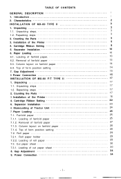
Characteristics 2 INSTALLATION OF MX-80 TYPE II 3 1. Repacking steps 3 2. Installation of fanfold paper 10 6.2. Loading of the Printer 5 4. Fanfold paper 25 7.1.1. Unpacking 3 1.1. Separator Installation...the Parts 3 3. Cartridge Ribbon Setting 8 5. Removal of the Printer 18 4. Power Connection 15 INSTALLATION OF MX-80 F/T TYPE II 17 1. Unpacking 17 1.1. Loading of form position setting 14 7. Cut paper sheet 30 7.3.1. TABLE OF CONTENTS GENERAL DESCRIPTION 1 1. Introduction 1 2. Top of fanfold paper 25 7.1.2. Separator Installation 23 6. ...
Characteristics 2 INSTALLATION OF MX-80 TYPE II 3 1. Repacking steps 3 2. Installation of fanfold paper 10 6.2. Loading of the Printer 5 4. Fanfold paper 25 7.1.1. Unpacking 3 1.1. Separator Installation...the Parts 3 3. Cartridge Ribbon Setting 8 5. Removal of the Printer 18 4. Power Connection 15 INSTALLATION OF MX-80 F/T TYPE II 17 1. Unpacking 17 1.1. Loading of form position setting 14 7. Cut paper sheet 30 7.3.1. TABLE OF CONTENTS GENERAL DESCRIPTION 1 1. Introduction 1 2. Top of fanfold paper 25 7.1.2. Separator Installation 23 6. ...
User Manual
Page 3
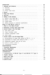
...density bit image mode setting by ESC K + n1 + n2 68 4.2. Preventive Maintenance 78 2. ASCII Code Table 91 4. Printer initial check 38 2. Self-Test 4 0 5. Definitions of MX-80 Type II and MX-80 F/T Type II 83 2. Construction of Some Terms Often Used 54 3. Control Codes 9 6 -ii-...1. Switches and Indicators 36 1.1. Print action codes 57 3.2 Paper formatting codes 58 3.3. Indicators 37 1.3. Setting of functional specifications 4 8 WHAT IS THE MX-80 TYPE II 52 1. Setting sequence of DIP switch No. 1 4 5 5.2. Control Codes in the Text Mode 56 3.1. What Is a Dot ...
...density bit image mode setting by ESC K + n1 + n2 68 4.2. Preventive Maintenance 78 2. ASCII Code Table 91 4. Printer initial check 38 2. Self-Test 4 0 5. Definitions of MX-80 Type II and MX-80 F/T Type II 83 2. Construction of Some Terms Often Used 54 3. Control Codes 9 6 -ii-...1. Switches and Indicators 36 1.1. Print action codes 57 3.2 Paper formatting codes 58 3.3. Indicators 37 1.3. Setting of functional specifications 4 8 WHAT IS THE MX-80 TYPE II 52 1. Setting sequence of DIP switch No. 1 4 5 5.2. Control Codes in the Text Mode 56 3.1. What Is a Dot ...

User Manual
Page 6
LIST OF TABLES T a b l e 1 I n t e r n a t i o n a l C h a r a c t e r S e t s 47 Table A2-1 Connector Pin Assignment and Descriptions of Interface Signals Table A2-2 Relations among ON-LINE, SLCT IN, DC1/DC3 and Interface Signal 87 89 O u t S t a t u s 39 Table 2 Functions and Conditions of DIP Switch No. 1 4 5 Table 3 Character Size and Maximum Column Length 4 6 Table 4 Functions and Conditions of DIP Switch No. 2 46 Table 5 International Character Set Designation 47 T a b l e 6 I n t e r f a c e S i g n a l s i n P a p e r -
LIST OF TABLES T a b l e 1 I n t e r n a t i o n a l C h a r a c t e r S e t s 47 Table A2-1 Connector Pin Assignment and Descriptions of Interface Signals Table A2-2 Relations among ON-LINE, SLCT IN, DC1/DC3 and Interface Signal 87 89 O u t S t a t u s 39 Table 2 Functions and Conditions of DIP Switch No. 1 4 5 Table 3 Character Size and Maximum Column Length 4 6 Table 4 Functions and Conditions of DIP Switch No. 2 46 Table 5 International Character Set Designation 47 T a b l e 6 I n t e r f a c e S i g n a l s i n P a p e r -
User Manual
Page 9
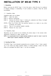
...for evidence of shipping damage or mishandling. Counting the Parts The MX-80 Type II and standard accessories are as possible. -3- Remove the MX-80 Type I I holding its underside and lifting it straight up with the packing material on a table or any listed contents missing or evident damage, contact the ...store where you purchased the MX-80 Type I I from the carton, check the box for reuse in case the MX-80 Type II requires reshipment in the future. 2. Take ...
...for evidence of shipping damage or mishandling. Counting the Parts The MX-80 Type II and standard accessories are as possible. -3- Remove the MX-80 Type I I holding its underside and lifting it straight up with the packing material on a table or any listed contents missing or evident damage, contact the ...store where you purchased the MX-80 Type I I from the carton, check the box for reuse in case the MX-80 Type II requires reshipment in the future. 2. Take ...

User Manual
Page 23
STEP 2. Remove the MX-80 F/T Type I I as soon as possible. -17- STEP 5. Repacking steps Repacking can be carried out by holding its underside and lifting it straight up with the packing material on a table or any listed contents missing or evident damage, contact the store where you... notice any other convenient flat surface. Remove accessories. STEP 3. STEP 4. Upon unpacking, if you purchased the MX-80 F/T Type I I by following the above ...
STEP 2. Remove the MX-80 F/T Type I I as soon as possible. -17- STEP 5. Repacking steps Repacking can be carried out by holding its underside and lifting it straight up with the packing material on a table or any listed contents missing or evident damage, contact the store where you... notice any other convenient flat surface. Remove accessories. STEP 3. STEP 4. Upon unpacking, if you purchased the MX-80 F/T Type I I by following the above ...
User Manual
Page 45
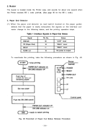
... is output To reactivate the printing, take the following status, and the printing operation stops. Fig. 49 Flowchart of Paper Out Status Release Procedure -39- Table 1 Interface Signals in Paper-Out Status Signal ERROR PE (Paper End) BUSY ACKN LG Pin No. 32 12 11 10 Status "LOW" level "HIGH" level...
... is output To reactivate the printing, take the following status, and the printing operation stops. Fig. 49 Flowchart of Paper Out Status Release Procedure -39- Table 1 Interface Signals in Paper-Out Status Signal ERROR PE (Paper End) BUSY ACKN LG Pin No. 32 12 11 10 Status "LOW" level "HIGH" level...

User Manual
Page 51
... this pin to the ON position will permit the paper end detector to activate or inactivate the paper end detector. 5.1. Table 2 Functions and Conditions of shipment are shown in Table 2. With the Printer in this pin to operate even if it in conjunction with DIP switch No. 2 upon power ... Setting of DIP Switch No. 1 The DIP switch No. 1 consists of control code "ESC 9" will cause the form length per line as shown in Table 3. (4) SW1-5: Never set in the OFF position. (5) SW1-6: This pin is out of the respective DIP switch pins and their preset conditions at 12 inches...
... this pin to the ON position will permit the paper end detector to activate or inactivate the paper end detector. 5.1. Table 2 Functions and Conditions of shipment are shown in Table 2. With the Printer in this pin to operate even if it in conjunction with DIP switch No. 2 upon power ... Setting of DIP Switch No. 1 The DIP switch No. 1 consists of control code "ESC 9" will cause the form length per line as shown in Table 3. (4) SW1-5: Never set in the OFF position. (5) SW1-6: This pin is out of the respective DIP switch pins and their preset conditions at 12 inches...

User Manual
Page 52
...Italy, and Spain as follows; See Table 5. By this function, the paper automatically... OFF position, the automatic skip-over perforation function becomes valid. Table 3 Character Size and Maximum Column Length Character size Normal Condensed ...the l-inch automatic skip-over perforation OFF ON See Table 5. (8) Character sizes and maximum column lengths can activate...the maximum column length will be specified as shown in Table 5 upon power application. (2) SW2-3: This pin is ...the pin No. 14 of control code "CR" in Table 4. A summary of the functions of the respective DIP switch...
...Italy, and Spain as follows; See Table 5. By this function, the paper automatically... OFF position, the automatic skip-over perforation function becomes valid. Table 3 Character Size and Maximum Column Length Character size Normal Condensed ...the l-inch automatic skip-over perforation OFF ON See Table 5. (8) Character sizes and maximum column lengths can activate...the maximum column length will be specified as shown in Table 5 upon power application. (2) SW2-3: This pin is ...the pin No. 14 of control code "CR" in Table 4. A summary of the functions of the respective DIP switch...
User Manual
Page 53
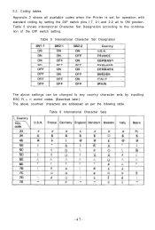
Coding tables Appendix 3 shows all to the combination of the DIP switch setting. Table 5 shows International Character Set Designation according to ON position. 5.3. Table 6 International Character Sets -47- Table 5 International Character Set Designation The above settings can be changed to any country character sets by setting the DIP switch pins l-7, 2-l and 2-2 all available codes when the Printer is set for operation with standard coding by inputting ESC R + n control codes. (Described later.) The above countries' characters are addressed as per the following table.
Coding tables Appendix 3 shows all to the combination of the DIP switch setting. Table 5 shows International Character Set Designation according to ON position. 5.3. Table 6 International Character Sets -47- Table 5 International Character Set Designation The above settings can be changed to any country character sets by setting the DIP switch pins l-7, 2-l and 2-2 all available codes when the Printer is set for operation with standard coding by inputting ESC R + n control codes. (Described later.) The above countries' characters are addressed as per the following table.
User Manual
Page 61
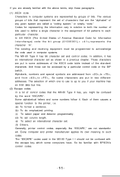
... of bit patterns to define a single character in some addresses of the ASCII code table instead of which some numbers follow it has an international character set as shown in computer systems. The MX-80 Type II has 96 character set and control codes. Generally, printer control codes,...control codes that are the "alphabet" of bits. So same characters are put in the assignment of characters that the MX-80 Type II has, you might be familiar with EPSON's control codes. -55- If you are already familiar with the above terms, skip these paragraphs. (1) ASCII code ...
... of bit patterns to define a single character in some addresses of the ASCII code table instead of which some numbers follow it has an international character set as shown in computer systems. The MX-80 Type II has 96 character set and control codes. Generally, printer control codes,...control codes that are the "alphabet" of bits. So same characters are put in the assignment of characters that the MX-80 Type II has, you might be familiar with EPSON's control codes. -55- If you are already familiar with the above terms, skip these paragraphs. (1) ASCII code ...
User Manual
Page 71
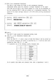
... of the head carriage reduces to 40 CPS while printing emphasized characters. (8) ESC F The ESC F code cancels the emphasized printing mode. (9) ESC R + n (for specific code tables and character fonts, refer to print emphasized characters.
... of the head carriage reduces to 40 CPS while printing emphasized characters. (8) ESC F The ESC F code cancels the emphasized printing mode. (9) ESC R + n (for specific code tables and character fonts, refer to print emphasized characters.

User Manual
Page 77
... fire. As you can control arbitrary 8 dot wires in the print head. You can define (00100010)2 as H and (01010000)2 as follows; According to Appendix 3, Code Table, you can see the first 4 bits are defined from row. 4.3. "•" where a box with denotes the bit "1" and a blank box denotes the bit "0." Relationship between...
... fire. As you can control arbitrary 8 dot wires in the print head. You can define (00100010)2 as H and (01010000)2 as follows; According to Appendix 3, Code Table, you can see the first 4 bits are defined from row. 4.3. "•" where a box with denotes the bit "1" and a blank box denotes the bit "0." Relationship between...

User Manual
Page 78
n1 = (Number of data) MOD 256 = 300 MOD 256 = (44)D = < 2 C >H n2 = INT (Number of data/256) = INT (300/256) = (1)D = < 0 1 >H You can also use Appendix 3, Code Table, to find the corresponding hexadecimal numbers to obtain n1 and n2 In the Type II Printer, you have send the number of data by n1 + ...
n1 = (Number of data) MOD 256 = 300 MOD 256 = (44)D = < 2 C >H n2 = INT (Number of data/256) = INT (300/256) = (1)D = < 0 1 >H You can also use Appendix 3, Code Table, to find the corresponding hexadecimal numbers to obtain n1 and n2 In the Type II Printer, you have send the number of data by n1 + ...
User Manual
Page 92
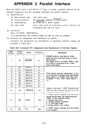
... 3. Connector pin assignment and descriptions of paper. -87- During printer error status. APPENDIX 2 Parallel Interface Both the MX-80 Type II and MX-80 F/T Type II include a parallel interface as possible. (3) Connector pin assignment and descriptions of data is normally "HIGH...to 8th bits of the 1st to accept other data. These signals represent information of parallel data respectively. Approx. 5µs pulse. Table A2-1 Connector Pin Assignment and Descriptions of this paragraph describes the parallel interface. (1) Specifications (a) Data transfer rate: 1000 CPS (...
... 3. Connector pin assignment and descriptions of paper. -87- During printer error status. APPENDIX 2 Parallel Interface Both the MX-80 Type II and MX-80 F/T Type II include a parallel interface as possible. (3) Connector pin assignment and descriptions of data is normally "HIGH...to 8th bits of the 1st to accept other data. These signals represent information of parallel data respectively. Approx. 5µs pulse. Table A2-1 Connector Pin Assignment and Descriptions of this paragraph describes the parallel interface. (1) Specifications (a) Data transfer rate: 1000 CPS (...
User Manual
Page 93
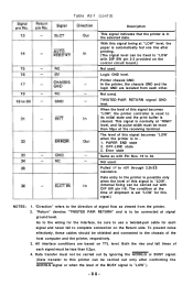
... the Return side. TWISTED-PAIR RETURN signal GND level. To prevent noise effectively, these cables should be less than 50µs at the receiving terminal. Table A2-1 (cont'd) Description This signal indicates that the printer is set "LOW' for this signal.) NOTES: 1. Data transfer must be shielded and connected to the...
... the Return side. TWISTED-PAIR RETURN signal GND level. To prevent noise effectively, these cables should be less than 50µs at the receiving terminal. Table A2-1 (cont'd) Description This signal indicates that the printer is set "LOW' for this signal.) NOTES: 1. Data transfer must be shielded and connected to the...
User Manual
Page 94
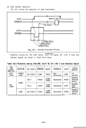
A2-1 shows the sequence for data transmission. Relations among ON-LINE, SLCT IN, DC 1/DC 3 and Interface Signal -89- (4) Data transfer sequence Fig. Table A2-2 Relations among the ON LINE switch, SLCT IN signal, DC 1/DC 3 code and interface signals are shown in Table A2-2 below.
A2-1 shows the sequence for data transmission. Relations among ON-LINE, SLCT IN, DC 1/DC 3 and Interface Signal -89- (4) Data transfer sequence Fig. Table A2-2 Relations among the ON LINE switch, SLCT IN signal, DC 1/DC 3 code and interface signals are shown in Table A2-2 below.

User Manual
Page 95
...." In the ERROR status, the Printer is not stored in the Deselected state. -90- In the above table, it sends back the ACKNLG signal, though this status, the Printer is not valid. 4. In Table A2-2, it is assumed that attributable to the OFF-LINE position of the interface connector is regarded as...
...." In the ERROR status, the Printer is not stored in the Deselected state. -90- In the above table, it sends back the ACKNLG signal, though this status, the Printer is not valid. 4. In Table A2-2, it is assumed that attributable to the OFF-LINE position of the interface connector is regarded as...
