Installation Guide - Control Pad and Touch Unit
Page 19
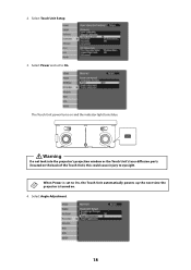
Select Power and set to On, the Touch Unit automatically powers up the next time the projector is set to eyesight. Warning Do not look into the projector's projection window or the Touch Unit's laser diffusion ports (located on and the indicator light turns blue. Select Touch Unit Setup. 3. Select Angle Adjustment. 18 2. this could cause injury to On. The Touch Unit power turns on the back of the Touch Unit); When Power is turned on. 4.
Select Power and set to On, the Touch Unit automatically powers up the next time the projector is set to eyesight. Warning Do not look into the projector's projection window or the Touch Unit's laser diffusion ports (located on and the indicator light turns blue. Select Touch Unit Setup. 3. Select Angle Adjustment. 18 2. this could cause injury to On. The Touch Unit power turns on the back of the Touch Unit); When Power is turned on. 4.
Installation Guide - Control Pad and Touch Unit
Page 33
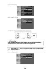
2. Warning Do not look into the projector's projection window or the Touch Unit's laser diffusion ports (located on and the indicator light turns blue. this could cause injury to On. The Touch Unit power turns on the back of the Touch Unit); When Power is turned on. 4. Select Power and set to On, the Touch Unit automatically powers up the next time the projector is set to eyesight. Select Touch Unit Setup. 3. Select Angle Adjustment. 32
2. Warning Do not look into the projector's projection window or the Touch Unit's laser diffusion ports (located on and the indicator light turns blue. this could cause injury to On. The Touch Unit power turns on the back of the Touch Unit); When Power is turned on. 4. Select Power and set to On, the Touch Unit automatically powers up the next time the projector is set to eyesight. Select Touch Unit Setup. 3. Select Angle Adjustment. 32
Installation Guide - Control Pad and Touch Unit
Page 43
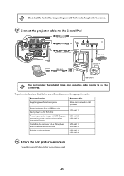
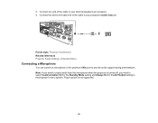
... that are not being used. 42 To perform the functions listed below, you will need to connect the appropriate cables: Projector function Required cables Supplying power from the projector Stereo mini connection cable (included) Projecting images from a USB flash drive Saving data to use the Control Pad. C Connect the projector cables...
... that are not being used. 42 To perform the functions listed below, you will need to connect the appropriate cables: Projector function Required cables Supplying power from the projector Stereo mini connection cable (included) Projecting images from a USB flash drive Saving data to use the Control Pad. C Connect the projector cables...
Installation Guide - Ultra-Short Throw Wall Mount ELPMB46
Page 2
...indicating an action that must not be done Symbol indicating an action that is damaged or modified. • Do not pull the power cord with too much force when routing the cable through the wall mount. 2 If anything other than a projector is designed specifically ... Epson® ELPMB46 wall mount. Keep this document. This symbol indicates related or useful information. The installation work (wall mounting) should be performed by this guide: • BrightLink® 475Wi/480i/485Wi/575Wi/575Wi+/585Wi/585Wi+/595Wi/595Wi+/675Wi+/685Wi/685Wi+/ 695Wi/695Wi+/696Ui/697Ui • BrightLink ...
...indicating an action that must not be done Symbol indicating an action that is damaged or modified. • Do not pull the power cord with too much force when routing the cable through the wall mount. 2 If anything other than a projector is designed specifically ... Epson® ELPMB46 wall mount. Keep this document. This symbol indicates related or useful information. The installation work (wall mounting) should be performed by this guide: • BrightLink® 475Wi/480i/485Wi/575Wi/575Wi+/585Wi/585Wi+/595Wi/595Wi+/675Wi+/685Wi/685Wi+/ 695Wi/695Wi+/696Ui/697Ui • BrightLink ...
Installation Guide - Ultra-Short Throw Wall Mount ELPMB46
Page 4
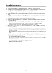
... projector (not including the Touch Unit). • Use the optional remote control cable set (model ELPKC28, part number V12H005C28) to supply power to the Control Pad in the following situations: • The required conditions above are not met. • The projection screen and the... If the projection screen and the Control Pad installation point are being used. 4 Installation Location • Before installing the projector, verify the power supply wiring for the Touch Unit to the projection surface. • Install the projector in a location where the projected image is within reach....
... projector (not including the Touch Unit). • Use the optional remote control cable set (model ELPKC28, part number V12H005C28) to supply power to the Control Pad in the following situations: • The required conditions above are not met. • The projection screen and the... If the projection screen and the Control Pad installation point are being used. 4 Installation Location • Before installing the projector, verify the power supply wiring for the Touch Unit to the projection surface. • Install the projector in a location where the projected image is within reach....

Installation Guide - Ultra-Short Throw Wall Mount ELPMB46
Page 5
... arm to the wall plate 30 Adjust the vertical slide position of the arm 32 Attach the projector to the wall mount 33 Connect the power cord and other cables to the projector 34 5
... arm to the wall plate 30 Adjust the vertical slide position of the arm 32 Attach the projector to the wall mount 33 Connect the power cord and other cables to the projector 34 5
Installation Guide - Ultra-Short Throw Wall Mount ELPMB46
Page 11
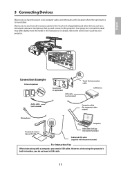
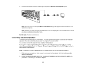
...projector's connection panel may differ slightly from the model in toolbar, you do not need a USB cable. Make sure you also have the power cord, computer cable, and other devices, such as a document camera or microphone, that you will connect to the projector. However, when ... (not included) Touch Unit connection cable LAN device Audio cable (not included) Computer cable (for computer video output) Microphone Computer Document camera (Epson DC-07) USB cable (for your projector. For details, refer to the online User's Guide for Easy Interactive Function) Dedicated USB cable (...
...projector's connection panel may differ slightly from the model in toolbar, you do not need a USB cable. Make sure you also have the power cord, computer cable, and other devices, such as a document camera or microphone, that you will connect to the projector. However, when ... (not included) Touch Unit connection cable LAN device Audio cable (not included) Computer cable (for computer video output) Microphone Computer Document camera (Epson DC-07) USB cable (for your projector. For details, refer to the online User's Guide for Easy Interactive Function) Dedicated USB cable (...

Installation Guide - Ultra-Short Throw Wall Mount ELPMB46
Page 12
... range specified in the installation instructions. It provides a convenient alternative to power the control pad, or the optional remote control cable set (model ELPKC28, part number V12H005C28). See the documentation included with the BrightLink Pro 1410Wi/1420Wi/1430Wi/1450Ui/1460Ui and BrightLink 697Ui projectors. Connecting the Control Pad The Control Pad is included...
... range specified in the installation instructions. It provides a convenient alternative to power the control pad, or the optional remote control cable set (model ELPKC28, part number V12H005C28). See the documentation included with the BrightLink Pro 1410Wi/1420Wi/1430Wi/1450Ui/1460Ui and BrightLink 697Ui projectors. Connecting the Control Pad The Control Pad is included...
Installation Guide - Ultra-Short Throw Wall Mount ELPMB46
Page 27
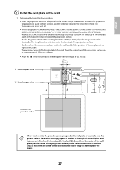
...the left or the right of the wall plate and is more than 4.9 inches (123.5 mm) from the center of the wall plate, the power plug will not fit under the cover. 27 Determine the template sheet position. • From the projection distance table, confirm the screen size (S), the... surface). If the outlet is between the projection image and temporary wall plate hole (d). • For the BrightLink 475Wi/480i/485Wi/575Wi/575Wi+/585Wi/585Wi+/595Wi/595Wi+/675Wi+/685Wi/ 685Wi+/695Wi/695Wi+, BrightLink Pro 1410Wi/1420Wi/1430Wi, and PowerLite 470/475W/480/ 485W/570/575W/580/585W/675W/680/685W, align ...
...the left or the right of the wall plate and is more than 4.9 inches (123.5 mm) from the center of the wall plate, the power plug will not fit under the cover. 27 Determine the template sheet position. • From the projection distance table, confirm the screen size (S), the... surface). If the outlet is between the projection image and temporary wall plate hole (d). • For the BrightLink 475Wi/480i/485Wi/575Wi/575Wi+/585Wi/585Wi+/595Wi/595Wi+/675Wi+/685Wi/ 685Wi+/695Wi/695Wi+, BrightLink Pro 1410Wi/1420Wi/1430Wi, and PowerLite 470/475W/480/ 485W/570/575W/580/585W/675W/680/685W, align ...
Installation Guide - Ultra-Short Throw Wall Mount ELPMB46
Page 34
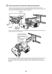
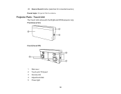
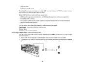
...the computer cable, HDMI cable, USB cable, Touch Unit connection cable (if applicable), Control Pad cables (if applicable), and power cord to the projector. Power cord Computer cable USB cable Touch Unit connection cable (if applicable) Use M4 screws (not included) to secure any necessary cables... such as external tuners, to keep the cables from Epson (part number ELPCK01). 34 See your projector's User Guide for detailed...
...the computer cable, HDMI cable, USB cable, Touch Unit connection cable (if applicable), Control Pad cables (if applicable), and power cord to the projector. Power cord Computer cable USB cable Touch Unit connection cable (if applicable) Use M4 screws (not included) to secure any necessary cables... such as external tuners, to keep the cables from Epson (part number ELPCK01). 34 See your projector's User Guide for detailed...
Users Guide
Page 9
... Colors are Incorrect 253 Solutions to Sound Problems ...254 Solutions to Microphone Problems 255 Solving Projector or Remote Control Operation Problems 255 Solutions to Projector Power or Shut-Off Problems 255 Solutions to Problems with the Remote Control 256 Solutions to Password Problems 257 Solving Interactive Problems...257 Solutions When "Error...
... Colors are Incorrect 253 Solutions to Sound Problems ...254 Solutions to Microphone Problems 255 Solving Projector or Remote Control Operation Problems 255 Solutions to Projector Power or Shut-Off Problems 255 Solutions to Problems with the Remote Control 256 Solutions to Password Problems 257 Solving Interactive Problems...257 Solutions When "Error...
Users Guide
Page 13
... or video device connection • Plug-and-play 3-in closed captioning decoder • Powerful 16 W speaker system with audio out port for connecting external speakers • Epson's Instant Off and Direct Power On features for quick setup and shut down • Support for connecting a microphone &#...; Optional wireless network support, including video and audio transfer • PC Free photo slide shows via connected USB memory devices or Epson document camera • Dual VGA ports for connections by multiple presenters • Port for connecting an external monitor • Port for...
... or video device connection • Plug-and-play 3-in closed captioning decoder • Powerful 16 W speaker system with audio out port for connecting external speakers • Epson's Instant Off and Direct Power On features for quick setup and shut down • Support for connecting a microphone &#...; Optional wireless network support, including video and audio transfer • PC Free photo slide shows via connected USB memory devices or Epson document camera • Dual VGA ports for connections by multiple presenters • Port for connecting an external monitor • Port for...

Users Guide
Page 15
... cable 8 Power cord 9 USB extension cable 10 Touch Unit connection cable (BrightLink 695Wi) 11 Password Protected sticker 12 Projector manuals and software download links CD 13 Projector software for Easy Interactive Function CD 14 Touch Unit (BrightLink 695Wi) 15 Markers (x2) (BrightLink 695Wi) 16 Labels (×4) (BrightLink 695Wi) 17 Tape for securing markers (BrightLink 695Wi) 18 Infrared deflectors (×8) (BrightLink 695Wi) Parent topic...
... cable 8 Power cord 9 USB extension cable 10 Touch Unit connection cable (BrightLink 695Wi) 11 Password Protected sticker 12 Projector manuals and software download links CD 13 Projector software for Easy Interactive Function CD 14 Touch Unit (BrightLink 695Wi) 15 Markers (x2) (BrightLink 695Wi) 16 Labels (×4) (BrightLink 695Wi) 17 Tape for securing markers (BrightLink 695Wi) 18 Infrared deflectors (×8) (BrightLink 695Wi) Parent topic...

Users Guide
Page 23
8 Monitor Out/Computer2 port 9 HDMI 2 port 10 HDMI 3 port 11 RS-232C port 12 SYNC In/Out port 13 Power inlet 14 Touch unit (TCH) port (BrightLink 695Wi) 15 USB-A port 16 Video port 17 Audio port 18 Audio Out port 19 Mic (microphone) port Parent topic: Projector Part Locations Related references Projector Light Status 23
8 Monitor Out/Computer2 port 9 HDMI 2 port 10 HDMI 3 port 11 RS-232C port 12 SYNC In/Out port 13 Power inlet 14 Touch unit (TCH) port (BrightLink 695Wi) 15 USB-A port 16 Video port 17 Audio port 18 Audio Out port 19 Mic (microphone) port Parent topic: Projector Part Locations Related references Projector Light Status 23
Users Guide
Page 25
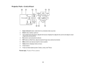
Control Panel 1 Source Search button (searches for connected video sources) 2 Enter button (selects options) 3 Horizontal/Vertical keystone adjustment buttons (display the adjustment screen and adjust screen shape) and arrow buttons 4 Esc button (cancels/exits functions) 5 W/T buttons (Wide/Tele; adjust projected image size) and arrow buttons 6 Menu button (accesses projector menu system) 7 Home button (displays home screen) 8 Power button 9 Projector status lights (power, Status, Lamp, and Temp) Parent topic: Projector Part Locations 25 Projector Parts -
Control Panel 1 Source Search button (searches for connected video sources) 2 Enter button (selects options) 3 Horizontal/Vertical keystone adjustment buttons (display the adjustment screen and adjust screen shape) and arrow buttons 4 Esc button (cancels/exits functions) 5 W/T buttons (Wide/Tele; adjust projected image size) and arrow buttons 6 Menu button (accesses projector menu system) 7 Home button (displays home screen) 8 Power button 9 Projector status lights (power, Status, Lamp, and Temp) Parent topic: Projector Part Locations 25 Projector Parts -
Users Guide
Page 29
1 Power button 2 Computer button (cycles through connected computer sources) 3 HDMI/Video button (cycles through connected HDMI/video sources) 4 Numeric buttons (enter numbers) 5 Auto button (automatically adjusts ...
1 Power button 2 Computer button (cycles through connected computer sources) 3 HDMI/Video button (cycles through connected HDMI/video sources) 4 Numeric buttons (enter numbers) 5 Auto button (automatically adjusts ...
Users Guide
Page 30
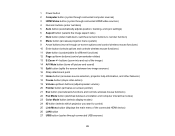
28 Source Search button (searches for connected sources) Parent topic: Projector Part Locations Projector Parts - Front (Cover On) Front (Cover Off) 1 Dial cover 2 Touch unit (TCH) port 3 Security slot 4 Adjustment dials 5 Power light 30 Touch Unit The Touch Unit comes with the BrightLink 695Wi projector only.
28 Source Search button (searches for connected sources) Parent topic: Projector Part Locations Projector Parts - Front (Cover On) Front (Cover Off) 1 Dial cover 2 Touch unit (TCH) port 3 Security slot 4 Adjustment dials 5 Power light 30 Touch Unit The Touch Unit comes with the BrightLink 695Wi projector only.
Users Guide
Page 46
... the sound from the external speakers when the projector is disabled when you connect external speakers. 1. You can also connect the projector to external self-powered speakers. You can control the volume using the projector's remote control. jack cable, or another type of cable or adapter. 46 Note: You may need...
... the sound from the external speakers when the projector is disabled when you connect external speakers. 1. You can also connect the projector to external self-powered speakers. You can control the volume using the projector's remote control. jack cable, or another type of cable or adapter. 46 Note: You may need...
Users Guide
Page 47
... Out port. 3. Connect one end of the cable to select Communication On for the Standby Mode setting and Always On for the A/V Output setting in power is turned off, you need to your external speakers as necessary. 4.
... Out port. 3. Connect one end of the cable to select Communication On for the Standby Mode setting and Always On for the A/V Output setting in power is turned off, you need to your external speakers as necessary. 4.
Users Guide
Page 49
...; USB Mass Storage Class-compliant (not all USB Mass Storage Class devices are supported) • Formatted in FAT or FAT32 • Self-powered by their own AC power supplies (bus-powered hard drives are not recommended) • Does not have multiple partitions You can connect your USB device came with... a power adapter, plug the device into an electrical outlet. 2. Connect the USB cable (or USB flash drive or USB memory card reader) ...
...; USB Mass Storage Class-compliant (not all USB Mass Storage Class devices are supported) • Formatted in FAT or FAT32 • Self-powered by their own AC power supplies (bus-powered hard drives are not recommended) • Does not have multiple partitions You can connect your USB device came with... a power adapter, plug the device into an electrical outlet. 2. Connect the USB cable (or USB flash drive or USB memory card reader) ...


