ESC/VP Level 21 Communication Manual
Page 1
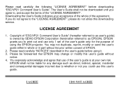
Downloading the User's Guide indicates your own risk. Please read carefully the following "LICENSE AGREEMENT" before using the EPSON projector. Please be downloaded until you do not agree to the "LICENSE AGREEMENT", please do not utilize this user's guide without the prior...of using it. 3. LICENSE AGREEMENT 1. Copyright of "ESC/VP21 Command User's Guide" (hereafter referred to as user's guide) is owned by SEIKO EPSON Corporation (hereinafter referred to as direct, indirect, special, incidental and consequential damages incurred due to whether or not you to , and accept the terms ...
Downloading the User's Guide indicates your own risk. Please read carefully the following "LICENSE AGREEMENT" before using the EPSON projector. Please be downloaded until you do not agree to the "LICENSE AGREEMENT", please do not utilize this user's guide without the prior...of using it. 3. LICENSE AGREEMENT 1. Copyright of "ESC/VP21 Command User's Guide" (hereafter referred to as user's guide) is owned by SEIKO EPSON Corporation (hereinafter referred to as direct, indirect, special, incidental and consequential damages incurred due to whether or not you to , and accept the terms ...
Installation Guide
Page 2
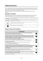
...or shock could possibly result in this guide before using the setting plate. Epson takes no responsibility for mounting a projector to vibration or shock. Keep this installation guide. Explanation of the projector and the setting plate before installation. If anything other than M8 could result.... Handle the power cable carefully. If the wall is mounted, the weight may result in the User's Guide for your projector when installing the setting plate. Warning Caution This symbol indicates information that is designed specifically for any horizontal vibration. Use M8 ...
...or shock could possibly result in this guide before using the setting plate. Epson takes no responsibility for mounting a projector to vibration or shock. Keep this installation guide. Explanation of the projector and the setting plate before installation. If anything other than M8 could result.... Handle the power cable carefully. If the wall is mounted, the weight may result in the User's Guide for your projector when installing the setting plate. Warning Caution This symbol indicates information that is designed specifically for any horizontal vibration. Use M8 ...

Installation Guide
Page 3
... damage. Such an environment may break, resulting in a location where the operating temperature for the installation location. • Install the projector away from other electric devices such as lubricants or oils on a regular basis to ensure there are any broken parts, stop using...setting plate. About This Installation Guide This guide describes how to mount the BrightLink™ 450 Wi, PowerLite® 460, and PowerLite 450W projectors to a wall using the setting plate immediately. If the projector or setting plate falls, it could cause personal injury or property damage.
... damage. Such an environment may break, resulting in a location where the operating temperature for the installation location. • Install the projector away from other electric devices such as lubricants or oils on a regular basis to ensure there are any broken parts, stop using...setting plate. About This Installation Guide This guide describes how to mount the BrightLink™ 450 Wi, PowerLite® 460, and PowerLite 450W projectors to a wall using the setting plate immediately. If the projector or setting plate falls, it could cause personal injury or property damage.

Installation Guide
Page 4
...board (2) Installation worksheet for projecting on a plain wall (3) Installation measurements in inches (4) Installation measurements in millimeters s Page 9 5 Installing the Projector (1) Install the wall plate on the wall (2) Determine the projection distance and pull out the slider (3) Attach the setting plate to the ...wall plate (4) Secure the projector to the setting plate (5) Connect the power cable and other cables to the projector s Page 18 6 Adjusting the Image s Page 22 (1) Turn on the projector (2) Display the test pattern (3) Change the aspect ratio ...
...board (2) Installation worksheet for projecting on a plain wall (3) Installation measurements in inches (4) Installation measurements in millimeters s Page 9 5 Installing the Projector (1) Install the wall plate on the wall (2) Determine the projection distance and pull out the slider (3) Attach the setting plate to the ...wall plate (4) Secure the projector to the setting plate (5) Connect the power cable and other cables to the projector s Page 18 6 Adjusting the Image s Page 22 (1) Turn on the projector (2) Display the test pattern (3) Change the aspect ratio ...

Installation Guide
Page 5
... hexagon socket head cap bolt with washer Quantity 2 Application For installing setting plate M5 x 12 mm hexagon socket head cap bolt with washer 2 For securing projector M4 x 12 mm hexagon socket head cap bolt without 2 For installing wall plate cover washer • Use the bolts supplied with any other types. •...
... hexagon socket head cap bolt with washer Quantity 2 Application For installing setting plate M5 x 12 mm hexagon socket head cap bolt with washer 2 For securing projector M4 x 12 mm hexagon socket head cap bolt without 2 For installing wall plate cover washer • Use the bolts supplied with any other types. •...

Installation Guide
Page 6
and Canada only. 6 Projector box Projector Remote control and AA batteries Power cord VGA computer cable USB cable* Interactive pens and AAA batteries* Epson Projector Software for Easy Interactive Function CD* Projector CD Epson Projector Software for Meeting and Monitoring CD Security sticker *Items included for the BrightLink 450Wi only. Extra pen and battery set are included in the U.S.
and Canada only. 6 Projector box Projector Remote control and AA batteries Power cord VGA computer cable USB cable* Interactive pens and AAA batteries* Epson Projector Software for Easy Interactive Function CD* Projector CD Epson Projector Software for Meeting and Monitoring CD Security sticker *Items included for the BrightLink 450Wi only. Extra pen and battery set are included in the U.S.

Installation Guide
Page 8
Make sure you have all necessary cables for Easy Interactive Function) Dedicated USB cable (supplied with document camera) 8 Connecting Devices Make sure you will connect to be installed. 3. Power cord Connection Example External speakers Audio ... or microphone, that you have the power cable, computer cable, USB cable, and other parts at the location where the setting plate is to the projector.
Make sure you have all necessary cables for Easy Interactive Function) Dedicated USB cable (supplied with document camera) 8 Connecting Devices Make sure you will connect to be installed. 3. Power cord Connection Example External speakers Audio ... or microphone, that you have the power cable, computer cable, USB cable, and other parts at the location where the setting plate is to the projector.

Installation Guide
Page 9
The distance of the projector from floor to bottom of the setting plate) also affects image size and position. If you are projecting on a plain wall, use the worksheet below. ... the adjustable arm of image area (f) 9 If you are projecting onto a pre-installed whiteboard, use the worksheet on the wall or whiteboard. Positioning the Projector The BrightLink 450Wi and PowerLite 450W can project up to 102 inches diagonally for an XGA image. English 4. The PowerLite 460 can project up to 96 inches diagonally...
The distance of the projector from floor to bottom of the setting plate) also affects image size and position. If you are projecting on a plain wall, use the worksheet below. ... the adjustable arm of image area (f) 9 If you are projecting onto a pre-installed whiteboard, use the worksheet on the wall or whiteboard. Positioning the Projector The BrightLink 450Wi and PowerLite 450W can project up to 102 inches diagonally for an XGA image. English 4. The PowerLite 460 can project up to 96 inches diagonally...

Installation Guide
Page 10
...:10). You may need to select a +10 inches smaller image size or move the board to a lower position on pages 12 to install the projector. For older equipment, this information. 4:3 XGA 16:10 WXGA 16:9 Widescreen (3) Using the tables on the wall. _____ total (10)After confirming your... image height (h), find the required distance between the top of the image area and _____ (b) the wall plate (b). (9) Determine the position for your projector installation by adding distances (f ) and (h). (6) Use the tables on pages 12 to 16 to determine the required distance from the top of the ...
...:10). You may need to select a +10 inches smaller image size or move the board to a lower position on pages 12 to install the projector. For older equipment, this information. 4:3 XGA 16:10 WXGA 16:9 Widescreen (3) Using the tables on the wall. _____ total (10)After confirming your... image height (h), find the required distance between the top of the image area and _____ (b) the wall plate (b). (9) Determine the position for your projector installation by adding distances (f ) and (h). (6) Use the tables on pages 12 to 16 to determine the required distance from the top of the ...

Installation Guide
Page 11
... projection distance (a) is 2.76 to 14.57 inches (7 to 37 cm). 10 in. (254 mm) 2.55 in the tables on page 18 to install the projector. The recommended range for all supported image sizes. Follow the instructions on the following pages to determine the projection distance and placement of the wall...
... projection distance (a) is 2.76 to 14.57 inches (7 to 37 cm). 10 in. (254 mm) 2.55 in the tables on page 18 to install the projector. The recommended range for all supported image sizes. Follow the instructions on the following pages to determine the projection distance and placement of the wall...

Installation Guide
Page 18
... the wall (1) Determine the template sheet position. • From the tables on pages 12 to 1.77 in the wall plate for the box. Installing the Projector Make sure to follow the steps below to use the cutout areas in . (45 mm). • Align the line (horizontal) of the template with the...
... the wall (1) Determine the template sheet position. • From the tables on pages 12 to 1.77 in the wall plate for the box. Installing the Projector Make sure to follow the steps below to use the cutout areas in . (45 mm). • Align the line (horizontal) of the template with the...

Installation Guide
Page 19
...mounting holes in the wall in . (7 to 37 cm). It is not strong enough, reinforce the wall before installation, and maintain the strength of the projector. (2) Loosen the four screws and pull out the slider on the wall with the mark on the wall. Warning ❏ When you mount the... 14.57 in the required locations. Use M8 nuts and bolts. Nuts and bolts smaller than M8 could cause the setting plate to fall. ❏ Epson takes no responsibility for projection distance (a) is a distance (a+x) equivalent to 16. See the tables on pages 12 to the distance (a) plus the thickness of ...
...mounting holes in the wall in . (7 to 37 cm). It is not strong enough, reinforce the wall before installation, and maintain the strength of the projector. (2) Loosen the four screws and pull out the slider on the wall with the mark on the wall. Warning ❏ When you mount the... 14.57 in the required locations. Use M8 nuts and bolts. Nuts and bolts smaller than M8 could cause the setting plate to fall. ❏ Epson takes no responsibility for projection distance (a) is a distance (a+x) equivalent to 16. See the tables on pages 12 to the distance (a) plus the thickness of ...

Installation Guide
Page 20
... the two M8 x 35 mm hexagon socket head cap bolts to the setting plate (1) Loosen the two screws and remove the cable cover from the projector. s 25 Setting plate Wall plate Wall plate bar Setting plate hook Cables M8 x 15 mm hexagon socket head cap bolts (one on left and one... on right) M8 x 35 mm hexagon socket head cap bolts (2) D Secure the projector to adjust the vertical position. C Attach the setting plate to trap the cables between the setting plate and wall plate. (3) Tighten the two M8 x 15...
... the two M8 x 35 mm hexagon socket head cap bolts to the setting plate (1) Loosen the two screws and remove the cable cover from the projector. s 25 Setting plate Wall plate Wall plate bar Setting plate hook Cables M8 x 15 mm hexagon socket head cap bolts (one on left and one... on right) M8 x 35 mm hexagon socket head cap bolts (2) D Secure the projector to adjust the vertical position. C Attach the setting plate to trap the cables between the setting plate and wall plate. (3) Tighten the two M8 x 15...

Installation Guide
Page 21
...projector Connect any necessary cables such as lubricants or oils on the projector and the setting plate (B). E Connect the power cable and other cables to prevent the screws from obstructing the image. If you are planning to the projector.... Slide plate M5 x 12 mm hexagon socket head cap bolts (2) Bolt positions Projector interface side Marks (3) Tighten the two M5 ... from the interface side of the projector (A). Align the marks on the slide plate, the case may crack and cause the projector to install or adjust the setting plate...
...projector Connect any necessary cables such as lubricants or oils on the projector and the setting plate (B). E Connect the power cable and other cables to prevent the screws from obstructing the image. If you are planning to the projector.... Slide plate M5 x 12 mm hexagon socket head cap bolts (2) Bolt positions Projector interface side Marks (3) Tighten the two M5 ... from the interface side of the projector (A). Align the marks on the slide plate, the case may crack and cause the projector to install or adjust the setting plate...

Installation Guide
Page 22
...Hold down the Fn key while pressing it may have an icon, or it . Remote Control Aspect Ratio Full 22 A Turn on the BrightLink 450Wi and the PowerLite 450W. Doing so may need to hold down the Fn key on the keyboard and press the function key that lets you...XGA image on the PowerLite 460. Pattern - Adjusting the Image To ensure maximum projection screen quality, follow the steps below to the signal for the projector: Settings menu Using Remote Control Using Control Panel C Change the aspect ratio if necessary You must connect a computer before you need to connect a...
...Hold down the Fn key while pressing it may have an icon, or it . Remote Control Aspect Ratio Full 22 A Turn on the BrightLink 450Wi and the PowerLite 450W. Doing so may need to hold down the Fn key on the keyboard and press the function key that lets you...XGA image on the PowerLite 460. Pattern - Adjusting the Image To ensure maximum projection screen quality, follow the steps below to the signal for the projector: Settings menu Using Remote Control Using Control Panel C Change the aspect ratio if necessary You must connect a computer before you need to connect a...

Installation Guide
Page 23
... and make the best use of the display area. • 16:9: Converts the aspect ratio of the image. s User's Guide for the projector: Configuration menu - The image may be cut off on the top and bottom depending on the resolution. Black bands may appear or images may ...lever (3) After you finish making the adjustment, close the air filter cover. 23 English Alternatively, set the aspect ratio from the Signal menu - BrightLink 450Wi and PowerLite 450W • Normal: Displays images using the full width of the projection area and maintains the aspect ratio of the image. Aspect....
... and make the best use of the display area. • 16:9: Converts the aspect ratio of the image. s User's Guide for the projector: Configuration menu - The image may be cut off on the top and bottom depending on the resolution. Black bands may appear or images may ...lever (3) After you finish making the adjustment, close the air filter cover. 23 English Alternatively, set the aspect ratio from the Signal menu - BrightLink 450Wi and PowerLite 450W • Normal: Displays images using the full width of the projection area and maintains the aspect ratio of the image. Aspect....

Installation Guide
Page 26
J Turn off the test pattern. If the screws are not tightened firmly, the projector or setting plate may fall and cause personal injury or property damage. 26 I After you finish making all screws firmly. Screws (4) E I Adjust the forward/backward slide Loosen the four screws and adjust the slider of the test pattern or computer image Press the Esc button on the remote control or control panel to , tighten the screws. Warning Tighten all of the adjustments in steps to turn off the display of the setting plate.
J Turn off the test pattern. If the screws are not tightened firmly, the projector or setting plate may fall and cause personal injury or property damage. 26 I After you finish making all screws firmly. Screws (4) E I Adjust the forward/backward slide Loosen the four screws and adjust the slider of the test pattern or computer image Press the Esc button on the remote control or control panel to , tighten the screws. Warning Tighten all of the adjustments in steps to turn off the display of the setting plate.

Installation Guide
Page 27
... cables are not installed inside the wall, you need to enlarge the cutouts to allow the cables to the User's Guide of your projector for maintenance and repairs. Refer to be passed through the cutouts on maintenance and repairs. 27 Attaching the Covers A Attach the wall ... cap (1) Secure the wall plate cover with the concave portion facing up (B). Cable cover Screws (2) Only a specialist should remove or reinstall the projector, including for instructions on each side of the wall plate cover. English 7. You may need to secure the cable cover. Wall plate cover M4...
... cables are not installed inside the wall, you need to enlarge the cutouts to allow the cables to the User's Guide of your projector for maintenance and repairs. Refer to be passed through the cutouts on maintenance and repairs. 27 Attaching the Covers A Attach the wall ... cap (1) Secure the wall plate cover with the concave portion facing up (B). Cable cover Screws (2) Only a specialist should remove or reinstall the projector, including for instructions on each side of the wall plate cover. English 7. You may need to secure the cable cover. Wall plate cover M4...

Installation Guide
Page 28
...to the supplied Quick Guide or the User's Guide on the BrightLink 450Wi CD-ROM. Warning ❏ Never loosen the bolts and nuts after installation. Appendix Using the Easy Interactive Function (BrightLink 450Wi Only) After you install the BrightLink 450Wi, you leave the pens, remote control, batteries, software CDs, ... After installation of the BrightLink 450Wi is to be left unattended, you find any loose screws, tighten them firmly. Confirm that the screws have not become loose on the setting plate. If the screws are not tightened firmly, the projector or setting plate may fall...
...to the supplied Quick Guide or the User's Guide on the BrightLink 450Wi CD-ROM. Warning ❏ Never loosen the bolts and nuts after installation. Appendix Using the Easy Interactive Function (BrightLink 450Wi Only) After you install the BrightLink 450Wi, you leave the pens, remote control, batteries, software CDs, ... After installation of the BrightLink 450Wi is to be left unattended, you find any loose screws, tighten them firmly. Confirm that the screws have not become loose on the setting plate. If the screws are not tightened firmly, the projector or setting plate may fall...

Installation Worksheets
Page 3
... the image area. Align the line (horizontal) on the template sheet with the (b) mark, then align the center line on the board to install the projector. © 2010 Epson America, Inc. 3/10 CPD-28017
... the image area. Align the line (horizontal) on the template sheet with the (b) mark, then align the center line on the board to install the projector. © 2010 Epson America, Inc. 3/10 CPD-28017


