User Manual
Page 3
... Parts Description 3 Equipment ...4 Motherboard Internal Connectors and Back Panel Connectors 5 I/O Panel description...6 Safety Instructions...6 Preparing the Motherboard 6 Hardware Installation 7 Installing the CPU and Fan 8 Installing Memory DIMMs 9 Installing the Motherboard 10 Installing the I/O Shield 10 Securing the Motherboard into the Chassis 10 Connecting Cables and Setting Switches 11 Power Connections 12 24-pin ATX Power (PWR1 12 8-pin ATX 12V Power (PWR2 12 Connecting IDE Hard Disk Drives 13 Connecting Serial ATA Cables 14 Connecting Internal Headers 15 Front Panel...
... Parts Description 3 Equipment ...4 Motherboard Internal Connectors and Back Panel Connectors 5 I/O Panel description...6 Safety Instructions...6 Preparing the Motherboard 6 Hardware Installation 7 Installing the CPU and Fan 8 Installing Memory DIMMs 9 Installing the Motherboard 10 Installing the I/O Shield 10 Securing the Motherboard into the Chassis 10 Connecting Cables and Setting Switches 11 Power Connections 12 24-pin ATX Power (PWR1 12 8-pin ATX 12V Power (PWR2 12 Connecting IDE Hard Disk Drives 13 Connecting Serial ATA Cables 14 Connecting Internal Headers 15 Front Panel...
User Manual
Page 7
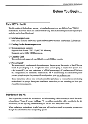
... microprocessor: Intel Core 2 Extreme, Intel Core 2 Quad, Intel Core 2 Duo Pentium EE, Pentium D, Pentium Cooling fan for your specific configuration, go through the installation instructions, we are building a PC, you will use most of the cables provided in a PC case, you will not need a minimum of the Kit This kit provides you go to install and connect your new EVGA nForce® 750i SLI motherboard. Power Supply The power supply requirement is...
... microprocessor: Intel Core 2 Extreme, Intel Core 2 Quad, Intel Core 2 Duo Pentium EE, Pentium D, Pentium Cooling fan for your specific configuration, go through the installation instructions, we are building a PC, you will use most of the cables provided in a PC case, you will not need a minimum of the Kit This kit provides you go to install and connect your new EVGA nForce® 750i SLI motherboard. Power Supply The power supply requirement is...
User Manual
Page 8
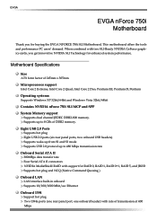
... NFORCE 750i SLI Motherboard. Motherboard Specifications Size ATX form factor of DDR2 memory. Supports up to 8 GBs of 245mm x 305mm Microprocessor support Intel Core 2 Extreme, Intel Core 2 Quad, Intel Core 2 Duo, Pentium EE, Pentium D, Pentium Operating systems: Supports Windows XP 32bit/64bit and Windows Vista 32bit/64bit Contains NVIDIA nForce 750i SLI MCP and SPP System Memory support Supports dual channel JEDEC DDR2-800 memory. Eight USB 2.0 Ports Supports hot plug Eight USB 2.0 ports (six rear panel ports, two onboard USB headers) Supports wake-up from S1 and S3 mode Supports...
... NFORCE 750i SLI Motherboard. Motherboard Specifications Size ATX form factor of DDR2 memory. Supports up to 8 GBs of 245mm x 305mm Microprocessor support Intel Core 2 Extreme, Intel Core 2 Quad, Intel Core 2 Duo, Pentium EE, Pentium D, Pentium Operating systems: Supports Windows XP 32bit/64bit and Windows Vista 32bit/64bit Contains NVIDIA nForce 750i SLI MCP and SPP System Memory support Supports dual channel JEDEC DDR2-800 memory. Eight USB 2.0 Ports Supports hot plug Eight USB 2.0 ports (six rear panel ports, two onboard USB headers) Supports wake-up from S1 and S3 mode Supports...

User Manual
Page 13
...-pin ATX power connector 5. Chassis fan connector 11. Reset CMOS button 16. Chipset fan connector 1 7 2 3 4 5 6 4 4 Figure 2. EVGA nForce 750i SLI Backpanel connectors 1. CPU fan connector 3. IDE connector 6. Serial-ATA (SATA) connectors 9. Battery 13. PCI Express x16 slots 26.1394a connector 27. Azalia HD Audio Header 22. nForce 750i SLI Motherboard 1. CPU 775 Socket 2. Post port 10. Auxiliary fan connector 17. Chassis fan2 connector 7. USB header 15. Power button 19. Reset button 20. Speaker 21. USB 2.0 ports (Six) 5. PCI slots 25. PS/2 Keyboard...
...-pin ATX power connector 5. Chassis fan connector 11. Reset CMOS button 16. Chipset fan connector 1 7 2 3 4 5 6 4 4 Figure 2. EVGA nForce 750i SLI Backpanel connectors 1. CPU fan connector 3. IDE connector 6. Serial-ATA (SATA) connectors 9. Battery 13. PCI Express x16 slots 26.1394a connector 27. Azalia HD Audio Header 22. nForce 750i SLI Motherboard 1. CPU 775 Socket 2. Post port 10. Auxiliary fan connector 17. Chassis fan2 connector 7. USB header 15. Power button 19. Reset button 20. Speaker 21. USB 2.0 ports (Six) 5. PCI slots 25. PS/2 Keyboard...

User Manual
Page 19
nForce 750i SLI Motherboard Power Connections 24-pin ATX Power PWR1 is the main power supply connector located along the edge of the board next to the connector and press firmly until seated. Firmly plug the power supply cable into the connector and make sure it is used to provide power to the CPU. Align the pins to the DIMM slots. Make sure that the power supply cable and pins are properly aligned with the connector on the motherboard. v Pin Assignments Connector Pin Signal 1 +3.3V 2 +3.3V...
nForce 750i SLI Motherboard Power Connections 24-pin ATX Power PWR1 is the main power supply connector located along the edge of the board next to the connector and press firmly until seated. Firmly plug the power supply cable into the connector and make sure it is used to provide power to the CPU. Align the pins to the DIMM slots. Make sure that the power supply cable and pins are properly aligned with the connector on the motherboard. v Pin Assignments Connector Pin Signal 1 +3.3V 2 +3.3V...

User Manual
Page 21
... Read Data 31 GND 32 Side 1 Select 33 NC 34 Diskette Change The current Serial ATA II interface allows up to the motherboard. There are four serial ATA connectors on the motherboard that support RAID 0,RAID 1, RAID 5, RAID 0+1 and JBOD configurations. nForce 750i SLI Motherboard Connecting Serial ATA Cables The Serial ATA II connector is used to connect the Serial ATA II device to 300MB/s data transfer rate. These connectors support the thin Serial ATA II cables for primary storage devices.
... Read Data 31 GND 32 Side 1 Select 33 NC 34 Diskette Change The current Serial ATA II interface allows up to the motherboard. There are four serial ATA connectors on the motherboard that support RAID 0,RAID 1, RAID 5, RAID 0+1 and JBOD configurations. nForce 750i SLI Motherboard Connecting Serial ATA Cables The Serial ATA II connector is used to connect the Serial ATA II device to 300MB/s data transfer rate. These connectors support the thin Serial ATA II cables for primary storage devices.

User Manual
Page 26
... the card into place. For Single Mode, insert the VGA card into the PCI slot, be sure that comply with the screw used to hold the blank cover. The x1 slot provides 250 MB/sec bandwidth. EVGA Expansion Slots The EVGA nForce 750i SLI motherboard contains six expansion slots, three PCI Express slots and three PCI slots. When installing a card into the "PCIE X16_1" VGA slot. (labeled on the top of PCI Express x16 graphics card supported by this motherboard supports two PCI-Express graphics cards with...
... the card into place. For Single Mode, insert the VGA card into the PCI slot, be sure that comply with the screw used to hold the blank cover. The x1 slot provides 250 MB/sec bandwidth. EVGA Expansion Slots The EVGA nForce 750i SLI motherboard contains six expansion slots, three PCI Express slots and three PCI slots. When installing a card into the "PCIE X16_1" VGA slot. (labeled on the top of PCI Express x16 graphics card supported by this motherboard supports two PCI-Express graphics cards with...

User Manual
Page 28
.../PCI Configurations PC Health Status Frequency/Voltage Control Enter BIOS Setup The BIOS is strongly recommended that you to the Phoenix-Award BIOS CMOS Setup Utility. nForce 750i SLI Motherboard Configuring the BIOS This section discusses how to change BIOS settings. 1. Pressing Del takes you do not change the default BIOS settings. This section includes the following message briefly displays at the bottom of the BIOS parameters are also provided. Detailed descriptions of the screen during the Power On Self Test (POST). Use...
.../PCI Configurations PC Health Status Frequency/Voltage Control Enter BIOS Setup The BIOS is strongly recommended that you to the Phoenix-Award BIOS CMOS Setup Utility. nForce 750i SLI Motherboard Configuring the BIOS This section discusses how to change BIOS settings. 1. Pressing Del takes you do not change the default BIOS settings. This section includes the following message briefly displays at the bottom of the BIOS parameters are also provided. Detailed descriptions of the screen during the Power On Self Test (POST). Use...

User Manual
Page 29
... and configure clocks, voltages, memory timings, and more. Use the Page Up and Page Down keys to scroll through the options or press Enter to obtain improved performance for overclocking. Advanced BIOS Features Use this menu to set up the advanced system features and boot sequence. AwardBIOS CMOS Setup Utility Standard CMOS Features Advanced BIOS Features Advanced Chipset Features Integrated Peripherals Power Management Setup PnP/PCI Configurations PC Health Status Frequency/Voltage Control Load Fail Safe Defaults Load Optimized Defaults Set Supervisor Password Set User Password Save...
... and configure clocks, voltages, memory timings, and more. Use the Page Up and Page Down keys to scroll through the options or press Enter to obtain improved performance for overclocking. Advanced BIOS Features Use this menu to set up the advanced system features and boot sequence. AwardBIOS CMOS Setup Utility Standard CMOS Features Advanced BIOS Features Advanced Chipset Features Integrated Peripherals Power Management Setup PnP/PCI Configurations PC Health Status Frequency/Voltage Control Load Fail Safe Defaults Load Optimized Defaults Set Supervisor Password Set User Password Save...
User Manual
Page 30
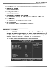
... settings to access the BIOS menu. To go back to display the sub-menu. Standard CMOS Features The Standard CMOS Features menu is used to CMOS and exit setup. Save & Exit Setup Use this command to configure the standard CMOS information, such as the date, time, HDD model, and so on the CMOS Setup Utility main menu are commands rather than submenus: Load Fail Safe Defaults Load default system settings. Set Supervisor Password/Set User Password Use this command to set, change, and disable the password used to abandon all setting changes...
... settings to access the BIOS menu. To go back to display the sub-menu. Standard CMOS Features The Standard CMOS Features menu is used to CMOS and exit setup. Save & Exit Setup Use this command to configure the standard CMOS information, such as the date, time, HDD model, and so on the CMOS Setup Utility main menu are commands rather than submenus: Load Fail Safe Defaults Load default system settings. Set Supervisor Password/Set User Password Use this command to set, change, and disable the password used to abandon all setting changes...

User Manual
Page 31
AwardBIOS CMOS Setup Utility Advanced BIOS Features CPU Features Removable Device Priority Hard Disk Boot Priority Quick Power On Self Test First Boot Device Second Boot Device Third Boot Device Boot Other Device Boot Up NumLock Status Security Option APIC Mode MPS Version Control For OS Full Screen LOGO Show [Press Enter] [Press Enter] [Press Enter] [Enabled] [Removable] [CDROM] [Hard Disk] [Enabled] [On] [Setup] [Enabled] [1.4] [Disabled] Item Help Main Level Select Removable Boot Device Priority :Move Enter:Select +/-/PU/PD:Value F10:Save ESC:Exit ...
AwardBIOS CMOS Setup Utility Advanced BIOS Features CPU Features Removable Device Priority Hard Disk Boot Priority Quick Power On Self Test First Boot Device Second Boot Device Third Boot Device Boot Other Device Boot Up NumLock Status Security Option APIC Mode MPS Version Control For OS Full Screen LOGO Show [Press Enter] [Press Enter] [Press Enter] [Enabled] [Removable] [CDROM] [Hard Disk] [Enabled] [On] [Setup] [Enabled] [1.4] [Disabled] Item Help Main Level Select Removable Boot Device Priority :Move Enter:Select +/-/PU/PD:Value F10:Save ESC:Exit ...

User Manual
Page 32
... keys to scroll through the options or press Enter to toggle between Enable and Disable. The Options are Pri. The options are Floppy, LS120, Hard Disk, CDROM, ZIP100, USB-FDD, USB-ZIP, USB-CDROM, Legacy LAN, Disabled. Select System to require a password to the CMOS Setup screen. APIC Mode Use this option to set to the various devices. nForce 750i SLI Motherboard the + or - To go to Enable, the system boots from some other device if the first/second/third boot devices fail. Hard Disk Boot Priority Use...
... keys to scroll through the options or press Enter to toggle between Enable and Disable. The Options are Pri. The options are Floppy, LS120, Hard Disk, CDROM, ZIP100, USB-FDD, USB-ZIP, USB-CDROM, Legacy LAN, Disabled. Select System to require a password to the CMOS Setup screen. APIC Mode Use this option to set to the various devices. nForce 750i SLI Motherboard the + or - To go to Enable, the system boots from some other device if the first/second/third boot devices fail. Hard Disk Boot Priority Use...
User Manual
Page 33
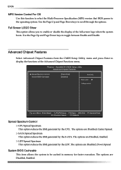
... Enable and Disable Advanced Chipset Features Select Advanced Chipset Features from the CMOS Setup Utility menu and press Enter to display the functions of the full-screen logo when the system boots. The options are Disabled, Enabled. EVGA MPS Version Control For OS Use this function to select the Multi-Processor Specification (MPS) version that BIOS passes to be cached in memory for faster execution. Use the Page Up and Page Down keys to enable or disable the display...
... Enable and Disable Advanced Chipset Features Select Advanced Chipset Features from the CMOS Setup Utility menu and press Enter to display the functions of the full-screen logo when the system boots. The options are Disabled, Enabled. EVGA MPS Version Control For OS Use this function to select the Multi-Processor Specification (MPS) version that BIOS passes to be cached in memory for faster execution. Use the Page Up and Page Down keys to enable or disable the display...

User Manual
Page 34
...Prefetch Mode [Enabled] [Auto] [Auto] [Auto] [Auto] [Enabled] [All Enabled] [Enabled] OnChip IDE Channel0 Use this function to display the IDE Function Setup menu. AwardBIOS CMOS Setup Utility Integrated Peripherals IDE Function Setup RAID Cofig OnChip USB USB Keyboard/Storage Support USB Mouse Support USB Park Mode USB TD Reads USB Periodic Data Reads USB Asyn Data Reads HD Audio MAC Lan MAC Media Interface IEEE1394 controller IDE HDD Black Mode Onboard FDC Controller Onbaord Serial Port 1 [Press Enter] [Press Enter] [V1.1+V2.0] [Enabled] [Disabled...
...Prefetch Mode [Enabled] [Auto] [Auto] [Auto] [Auto] [Enabled] [All Enabled] [Enabled] OnChip IDE Channel0 Use this function to display the IDE Function Setup menu. AwardBIOS CMOS Setup Utility Integrated Peripherals IDE Function Setup RAID Cofig OnChip USB USB Keyboard/Storage Support USB Mouse Support USB Park Mode USB TD Reads USB Periodic Data Reads USB Asyn Data Reads HD Audio MAC Lan MAC Media Interface IEEE1394 controller IDE HDD Black Mode Onboard FDC Controller Onbaord Serial Port 1 [Press Enter] [Press Enter] [V1.1+V2.0] [Enabled] [Disabled...
User Manual
Page 36
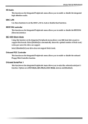
... to set the MAC LAN to automatically detect the optimal number of block read/ writes per sector the drive can support. Select [Disabled] if your IDE hard drive needs to support block mode. IDE HDD Block Mode Using this function on the Integrated Peripherals menu allows your drive does not support block mode. nForce 750i SLI Motherboard HD Audio This function on the Integrated Peripherals menu allows you to enable or disable the IEEE1394 (Firewire) interface. Options...
... to set the MAC LAN to automatically detect the optimal number of block read/ writes per sector the drive can support. Select [Disabled] if your IDE hard drive needs to support block mode. IDE HDD Block Mode Using this function on the Integrated Peripherals menu allows your drive does not support block mode. nForce 750i SLI Motherboard HD Audio This function on the Integrated Peripherals menu allows you to enable or disable the IEEE1394 (Firewire) interface. Options...
User Manual
Page 37
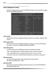
...] [User Define] [DPMS Support] [Disabled] [Instant-Off] [Disabled] [Disabled] [Disabled] 0 0 : 0 : 0 [Enabled] [BUTTON ONLY] Enter Ctrl-F1 [Former-Sts] Item Help Main Level :Move Enter:Select +/-/PU/PD:Value F10:Save ESC:Exit F1:General Help F5: Previous Values F7:Defaults ACPI Function This function on the Power Management Setup menu allows you to set Soft-Off by PBNT to enable or disable the ACPI function. AwardBIOS CMOS Setup Utility Power Management Setup ACPI function APCI Suspend Type Power...
...] [User Define] [DPMS Support] [Disabled] [Instant-Off] [Disabled] [Disabled] [Disabled] 0 0 : 0 : 0 [Enabled] [BUTTON ONLY] Enter Ctrl-F1 [Former-Sts] Item Help Main Level :Move Enter:Select +/-/PU/PD:Value F10:Save ESC:Exit F1:General Help F5: Previous Values F7:Defaults ACPI Function This function on the Power Management Setup menu allows you to set Soft-Off by PBNT to enable or disable the ACPI function. AwardBIOS CMOS Setup Utility Power Management Setup ACPI function APCI Suspend Type Power...
User Manual
Page 38
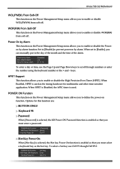
..., use Ctrl+F1 though Ctrl+F12 POWER ON Function x KB Power ON Password Hot Key Power On [Hot key] Enter [Ctrl-F1] nForce 750i SLI Motherboard WOL(PME#) From Soft-Off This function on the Power Management Setup menu allows you to enable or disable WOL(PMW#) from soft-off . HPET Support This function allows you must enter a password. When Enabled, HPET is enabled so that you to enable or disable the High Precision Even Timer (HPET). Options...
..., use Ctrl+F1 though Ctrl+F12 POWER ON Function x KB Power ON Password Hot Key Power On [Hot key] Enter [Ctrl-F1] nForce 750i SLI Motherboard WOL(PME#) From Soft-Off This function on the Power Management Setup menu allows you to enable or disable WOL(PMW#) from soft-off . HPET Support This function allows you must enter a password. When Enabled, HPET is enabled so that you to enable or disable the High Precision Even Timer (HPET). Options...

User Manual
Page 39
... return to [Enabled] if you have installed a new add-on and the system reconfiguration has caused a serious conflict that prevents the OS from booting. Off: The system stays off after a power failure. AwardBIOS CMOS Setup Utility PnP/PCI Configuration Init Display First Reset Configuration Data Resources Controlled By x IRQ Resources [PCI Slot] [Disabled] [Auto(ESCD)] Press Enter Item Help Main Level PCI/VGA Express Snoop [Disabled] ** PCI Express relative items ** Maximum Payload Size [4096] :Move Enter:Select +/-/PU...
... return to [Enabled] if you have installed a new add-on and the system reconfiguration has caused a serious conflict that prevents the OS from booting. Off: The system stays off after a power failure. AwardBIOS CMOS Setup Utility PnP/PCI Configuration Init Display First Reset Configuration Data Resources Controlled By x IRQ Resources [PCI Slot] [Disabled] [Auto(ESCD)] Press Enter Item Help Main Level PCI/VGA Express Snoop [Disabled] ** PCI Express relative items ** Maximum Payload Size [4096] :Move Enter:Select +/-/PU...
User Manual
Page 41
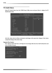
... Health Status from the CMOS Setup Utility menu and press Enter to display the PC Health Status menu. Most fans have built-in Blue are dynamic and change as the speed and voltages of the various components change with system usage. Phoenix - AwardBIOS CMOS Setup Utility PC Health Status Dynamic Fan Control CPU CPU VID CPU FSB Memory +3.3V +3.3V Dual +12V +5V +Vbat CPU Fan Speed Aux Fan Speed nForce Fan Speed Chassis Fan2 Speed 0 RPM [Press Enter] 47ºC/ 117º...
... Health Status from the CMOS Setup Utility menu and press Enter to display the PC Health Status menu. Most fans have built-in Blue are dynamic and change as the speed and voltages of the various components change with system usage. Phoenix - AwardBIOS CMOS Setup Utility PC Health Status Dynamic Fan Control CPU CPU VID CPU FSB Memory +3.3V +3.3V Dual +12V +5V +Vbat CPU Fan Speed Aux Fan Speed nForce Fan Speed Chassis Fan2 Speed 0 RPM [Press Enter] 47ºC/ 117º...

User Manual
Page 42
...- The options are from the CMOS Setup Utility menu and press Enter to display the Frequency/Voltage Control menu. System Clocks From this item to scroll through 60 X. nForce 750i SLI Motherboard Frequency/Voltage Control Select Frequency/Voltage Control from 6 X through the options. FSB Clock, MHz This value is set by the system (value cannot be changed by the user). LDT Frequency Use this menu, display the frequency settings. Parameters **Frequency Settings** Current CPU Freq, MHz FSB Clock, MHz Settings Current Value 2400.0 800.0 2400.0 800.0 Current CPU Freq...
...- The options are from the CMOS Setup Utility menu and press Enter to display the Frequency/Voltage Control menu. System Clocks From this item to scroll through 60 X. nForce 750i SLI Motherboard Frequency/Voltage Control Select Frequency/Voltage Control from 6 X through the options. FSB Clock, MHz This value is set by the system (value cannot be changed by the user). LDT Frequency Use this menu, display the frequency settings. Parameters **Frequency Settings** Current CPU Freq, MHz FSB Clock, MHz Settings Current Value 2400.0 800.0 2400.0 800.0 Current CPU Freq...


