User Manual
Page 2
User Guide EVGA nForce 750i SLI Motherboard
User Guide EVGA nForce 750i SLI Motherboard
User Manual
Page 7
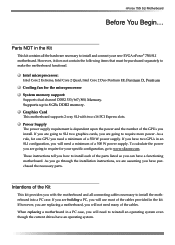
...www.slizone.com. To calculate the power you are going to require for your new EVGA nForce® 750i SLI motherboard. Parts NOT in the kit. Graphics Card This motherboard supports 2-way SLI with the motherboard and all the hardware necessary to reinstall an operating system even though the current drives..., Intel Core 2 Duo Pentium EE, Pentium D, Pentium Cooling fan for one GPU you with two x16 PCI Express slots. nForce 750i SLI Motherboard Before You Begin... Intentions of the cables. However, it does not contain the following items that must be purchased separately to install the...
...www.slizone.com. To calculate the power you are going to require for your new EVGA nForce® 750i SLI motherboard. Parts NOT in the kit. Graphics Card This motherboard supports 2-way SLI with the motherboard and all the hardware necessary to reinstall an operating system even though the current drives..., Intel Core 2 Duo Pentium EE, Pentium D, Pentium Cooling fan for one GPU you with two x16 PCI Express slots. nForce 750i SLI Motherboard Before You Begin... Intentions of the cables. However, it does not contain the following items that must be purchased separately to install the...
User Manual
Page 8
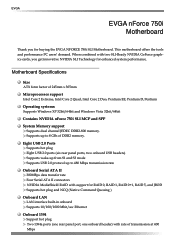
... MediaShield RAID with support for buying the EVGA NFORCE 750i SLI Motherboard. EVGA EVGA nForce 750i Motherboard Thank you get innovative NVIDIA SLI Technology for enhanced system performance. This motherboard offers the tools and performance PC users' demand. When combined with two SLI-Ready NVIDIA GeForce graphics cards, you for.../64bit and Windows Vista 32bit/64bit Contains NVIDIA nForce 750i SLI MCP and SPP System Memory support Supports dual channel JEDEC DDR2-800 memory. Supports up to 8 GBs of DDR2 memory. Motherboard Specifications Size ATX form factor of transmission at ...
... MediaShield RAID with support for buying the EVGA NFORCE 750i SLI Motherboard. EVGA EVGA nForce 750i Motherboard Thank you get innovative NVIDIA SLI Technology for enhanced system performance. This motherboard offers the tools and performance PC users' demand. When combined with two SLI-Ready NVIDIA GeForce graphics cards, you for.../64bit and Windows Vista 32bit/64bit Contains NVIDIA nForce 750i SLI MCP and SPP System Memory support Supports dual channel JEDEC DDR2-800 memory. Supports up to 8 GBs of DDR2 memory. Motherboard Specifications Size ATX form factor of transmission at ...

User Manual
Page 9
off) Expansion Slots Three PCI slots One PCI Express x1 slot Two PCI Express x16 Graphics slot compliant with PCI Express 2.0 nForce 750i SLI Motherboard Onboard Audio Azalia High-Definition audio Supports 8-channel audio Supports S/PDIF output Supports Jack-Sensing function Green Function Supports ACPI (Advanced Configuration and Power Interface) Supports S0 (normal), S1 (power on suspend), S3 (suspend to RAM), S4 (Suspend to disk depends on OS), and S5 (soft -
off) Expansion Slots Three PCI slots One PCI Express x1 slot Two PCI Express x16 Graphics slot compliant with PCI Express 2.0 nForce 750i SLI Motherboard Onboard Audio Azalia High-Definition audio Supports 8-channel audio Supports S/PDIF output Supports Jack-Sensing function Green Function Supports ACPI (Advanced Configuration and Power Interface) Supports S0 (normal), S1 (power on suspend), S3 (suspend to RAM), S4 (Suspend to disk depends on OS), and S5 (soft -
User Manual
Page 10
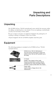
...protect internet components from dust and foreign objects and aids in this kit are replacing a motherboard, you may not need many of equipment shipped in the NVIDIA nForce 750i SLI motherboard box. All parts shipped in proper airflow within the chassis. If you are RoHS-...lead-free) parts. Equipment The following equipment is missing or damaged, contact your reseller. NVIDIA nForce 750i SLI Motherboard This PCI Express motherboard contains the NVIDIA nForce 750i SLI SPP and MCP and is SLI-ready. Floppy Cable Used to attach a floppy drive to a new chassis. Unpacking and Parts...
...protect internet components from dust and foreign objects and aids in this kit are replacing a motherboard, you may not need many of equipment shipped in the NVIDIA nForce 750i SLI motherboard box. All parts shipped in proper airflow within the chassis. If you are RoHS-...lead-free) parts. Equipment The following equipment is missing or damaged, contact your reseller. NVIDIA nForce 750i SLI Motherboard This PCI Express motherboard contains the NVIDIA nForce 750i SLI SPP and MCP and is SLI-ready. Floppy Cable Used to attach a floppy drive to a new chassis. Unpacking and Parts...

User Manual
Page 13
... Mic In Orange Black Rear Speaker Out Grey 7. DDR2 DIMM slots 0 - 3 4. 24-pin ATX power connector 5. Serial connector 12. PCI Express x1 slot 28. EVGA nForce 750i SLI Backpanel connectors 1. nForce 750i SLI Motherboard 1. Serial-ATA (SATA) connectors 9. Chipset fan connector 1 7 2 3 4 5 6 4 4 Figure 2. Battery 13. Front panel connector 14. System fan connector 18. PS/2 Mouse Port 2. Chassis fan2 connector...
... Mic In Orange Black Rear Speaker Out Grey 7. DDR2 DIMM slots 0 - 3 4. 24-pin ATX power connector 5. Serial connector 12. PCI Express x1 slot 28. EVGA nForce 750i SLI Backpanel connectors 1. nForce 750i SLI Motherboard 1. Serial-ATA (SATA) connectors 9. Chipset fan connector 1 7 2 3 4 5 6 4 4 Figure 2. Battery 13. Front panel connector 14. System fan connector 18. PS/2 Mouse Port 2. Chassis fan2 connector...

User Manual
Page 15
...instruction that came with notches on the load plate to protect the socket when there is fully seated and level in the processor with this motherboard. Make sure not to save the cover so that can be used with the notches on the back. Use the following procedure to ...socket cover from the load plate. 4. It is correct for your chassis type and your fan assembly. Hold the processor only by the edges. nForce 750i SLI Motherboard Installing the CPU Be very careful when handling the CPU. Lower the processor straight down while you have a safe place to install the CPU ...
...instruction that came with notches on the load plate to protect the socket when there is fully seated and level in the processor with this motherboard. Make sure not to save the cover so that can be used with the notches on the back. Use the following procedure to ...socket cover from the load plate. 4. It is correct for your chassis type and your fan assembly. Hold the processor only by the edges. nForce 750i SLI Motherboard Installing the CPU Be very careful when handling the CPU. Lower the processor straight down while you have a safe place to install the CPU ...

User Manual
Page 17
nForce 750i SLI Motherboard Installing the Motherboard The sequence of a short circuit. Also make sure it would need to the fan assembly in- Press the I /O shield that is aligned with an empty chassis. If there are replacing an existing motherboard or working with the chassis vents according to obtain the... radio frequency transmissions, protects internal components from the inside the chassis. 2. If the I /O shield and secure the motherboard into place and for the expansion cards. It is recommended that you are studs that stud to -ten screws. Before installing the...
nForce 750i SLI Motherboard Installing the Motherboard The sequence of a short circuit. Also make sure it would need to the fan assembly in- Press the I /O shield that is aligned with an empty chassis. If there are replacing an existing motherboard or working with the chassis vents according to obtain the... radio frequency transmissions, protects internal components from the inside the chassis. 2. If the I /O shield and secure the motherboard into place and for the expansion cards. It is recommended that you are studs that stud to -ten screws. Before installing the...

User Manual
Page 19
Make sure that the power supply cable and pins are properly aligned with the connector on the motherboard. v Pin Assignments Connector Pin Signal 1 +3.3V 2 +3.3V 3 GND 4 +5V 5 GND 6 +5V 7 GND 8 PWROK 9 +5V_AUX 10 +12V 11 +12V 12 +3.3V Pin Signal 13 +3.3V 14 -... 22 +5V 23 +5V 24 GND 8-pin ATX 12V Power The 8-pin ATX 12V power connection, is used to provide power to the DIMM slots. nForce 750i SLI Motherboard Power Connections 24-pin ATX Power PWR1 is the main power supply connector located along the edge of the board next to the CPU. Align...
Make sure that the power supply cable and pins are properly aligned with the connector on the motherboard. v Pin Assignments Connector Pin Signal 1 +3.3V 2 +3.3V 3 GND 4 +5V 5 GND 6 +5V 7 GND 8 PWROK 9 +5V_AUX 10 +12V 11 +12V 12 +3.3V Pin Signal 13 +3.3V 14 -... 22 +5V 23 +5V 24 GND 8-pin ATX 12V Power The 8-pin ATX 12V power connection, is used to provide power to the DIMM slots. nForce 750i SLI Motherboard Power Connections 24-pin ATX Power PWR1 is the main power supply connector located along the edge of the board next to the CPU. Align...

User Manual
Page 21
... 30 Read Data 31 GND 32 Side 1 Select 33 NC 34 Diskette Change There are four serial ATA connectors on the motherboard that support RAID 0,RAID 1, RAID 5, RAID 0+1 and JBOD configurations. The current Serial ATA II interface allows up to the... Connector SATA B1 SATA B0 SATA A0 (bottom) SATA A1 (top) Pin Signal 1 GND 2 TX+ 3 TX- 4 GND 5 RX+ 6 RX- 7 GND Connecting Floppy Disk Drive The motherboard supports a standard 360K, 720K, 1.2M, 1.44m, and a 2.88M floppy disk drive (FDD). nForce 750i SLI Motherboard Connecting Serial ATA Cables The Serial ATA II connector is ...
... 30 Read Data 31 GND 32 Side 1 Select 33 NC 34 Diskette Change There are four serial ATA connectors on the motherboard that support RAID 0,RAID 1, RAID 5, RAID 0+1 and JBOD configurations. The current Serial ATA II interface allows up to the... Connector SATA B1 SATA B0 SATA A0 (bottom) SATA A1 (top) Pin Signal 1 GND 2 TX+ 3 TX- 4 GND 5 RX+ 6 RX- 7 GND Connecting Floppy Disk Drive The motherboard supports a standard 360K, 720K, 1.2M, 1.44m, and a 2.88M floppy disk drive (FDD). nForce 750i SLI Motherboard Connecting Serial ATA Cables The Serial ATA II connector is ...
User Manual
Page 23
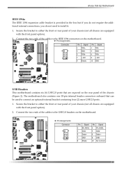
nForce 750i SLI Motherboard IEEE 1394a The IEEE 1394 expansion cable bracket is provided in the box but if...of the chassis (Figure 2). Connect the two ends of the cables to the IEEE 1394 connectors on the motherboard. v Pin Assignments Connector Pin Signal 1 5V_DUAL 3 Data5 Data+ 7 GND 9 Empty Pin Signal 2 5V_DUAL 4 Data6 Data+ 8 GND...are equipped with the front panel option). 2. Connect the two ends of the cables to the USB 2.0 headers on the motherboard. v Pin Assignments Connector Pin Signal 1 TPA+ 3 GND 5 TPB+ 7 +12V 9 Empty Pin Signal 2 TPA4 GND 6 TPB8 +...
nForce 750i SLI Motherboard IEEE 1394a The IEEE 1394 expansion cable bracket is provided in the box but if...of the chassis (Figure 2). Connect the two ends of the cables to the IEEE 1394 connectors on the motherboard. v Pin Assignments Connector Pin Signal 1 5V_DUAL 3 Data5 Data+ 7 GND 9 Empty Pin Signal 2 5V_DUAL 4 Data6 Data+ 8 GND...are equipped with the front panel option). 2. Connect the two ends of the cables to the USB 2.0 headers on the motherboard. v Pin Assignments Connector Pin Signal 1 TPA+ 3 GND 5 TPB+ 7 +12V 9 Empty Pin Signal 2 TPA4 GND 6 TPB8 +...

User Manual
Page 25
The fan speed can be either a 3-pin or a 4-pin connector. CHASSIS FAN2 NFORCE FAN: Install the fan over the nForce 750i SLI SPP to this installation, these may not be detected and viewed in the PC Health Status section of the CMOS Setup. v Pin ... plug into a 3-pin connector. Connect a 3-pin connector to pins 1, 2, and 3 on the motherboard. For this connrctor. The fans are six fan connections on the motherboard. The CPU fan cable can be used. nForce 750i SLI Motherboard Fan Connections There are automatically turned off after the system enters S3, S4 and S5 mode. CPU FAN...
The fan speed can be either a 3-pin or a 4-pin connector. CHASSIS FAN2 NFORCE FAN: Install the fan over the nForce 750i SLI SPP to this installation, these may not be detected and viewed in the PC Health Status section of the CMOS Setup. v Pin ... plug into a 3-pin connector. Connect a 3-pin connector to pins 1, 2, and 3 on the motherboard. For this connrctor. The fans are six fan connections on the motherboard. The CPU fan cable can be used. nForce 750i SLI Motherboard Fan Connections There are automatically turned off after the system enters S3, S4 and S5 mode. CPU FAN...

User Manual
Page 26
... many expansion cards such as a modem or LAN card. The design of this motherboard, go to www.nvidia.com/estore. For Single Mode, insert the VGA card into place. EVGA Expansion Slots The EVGA nForce 750i SLI motherboard contains six expansion slots, three PCI Express slots and three PCI slots. Secure the... card, be sure that is fully seated. The x1 slot provides 250 MB/sec bandwidth. If the card is purchased separately from the motherboard). The "PCIE X16_2" VGA slot will become inactive. When installing a card into the PCI slot, be sure the retention clip snaps ...
... many expansion cards such as a modem or LAN card. The design of this motherboard, go to www.nvidia.com/estore. For Single Mode, insert the VGA card into place. EVGA Expansion Slots The EVGA nForce 750i SLI motherboard contains six expansion slots, three PCI Express slots and three PCI slots. Secure the... card, be sure that is fully seated. The x1 slot provides 250 MB/sec bandwidth. If the card is purchased separately from the motherboard). The "PCIE X16_2" VGA slot will become inactive. When installing a card into the PCI slot, be sure the retention clip snaps ...

User Manual
Page 27
... Provides two-digit POST code to show why the system fail to store all the set parameters. CMOS Button: The motherboard uses the CMOS RAM to boot. Allows quick and easy optimization. nForce 750i SLI Motherboard Onboard Buttons These onboard buttons include RESET, POWER and CMOS , lets you turn on/off the system easily, and...
... Provides two-digit POST code to show why the system fail to store all the set parameters. CMOS Button: The motherboard uses the CMOS RAM to boot. Allows quick and easy optimization. nForce 750i SLI Motherboard Onboard Buttons These onboard buttons include RESET, POWER and CMOS , lets you turn on/off the system easily, and...

User Manual
Page 28
Pressing Del takes you do not change the default BIOS settings. Power on the computer. 2. nForce 750i SLI Motherboard Configuring the BIOS This section discusses how to change BIOS settings. 1. Note: It is strongly recommended that you to verify/change the system settings through ...
Pressing Del takes you do not change the default BIOS settings. Power on the computer. 2. nForce 750i SLI Motherboard Configuring the BIOS This section discusses how to change BIOS settings. 1. Note: It is strongly recommended that you to verify/change the system settings through ...
User Manual
Page 30
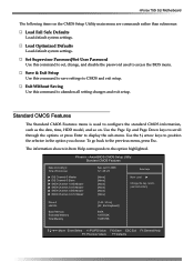
... Utility Standard CMOS Features Date (mm:dd:yy) Time (hh:mm:ss) IDE Channel 0 Master IDE Channel 0 Slave SATA Channel 1 (A0) Master SATA Channel 2 (A1) Master SATA Channel 3 (B0) Master SATA Channel 4 (C1) Master Sat, Jul 01 2006 12 : 48: 23 [None] [None] [None] [None] [None..., But Keyboard] 640K 1047552K 1048576K :Move Enter:Select +/-/PU/PD:Value F10:Save ESC:Exit F1:General Help F5: Previous Values F7:Defaults nForce 750i SLI Motherboard The following items on . Set Supervisor Password/Set User Password Use this command to save settings to access the BIOS menu. Save & Exit...
... Utility Standard CMOS Features Date (mm:dd:yy) Time (hh:mm:ss) IDE Channel 0 Master IDE Channel 0 Slave SATA Channel 1 (A0) Master SATA Channel 2 (A1) Master SATA Channel 3 (B0) Master SATA Channel 4 (C1) Master Sat, Jul 01 2006 12 : 48: 23 [None] [None] [None] [None] [None..., But Keyboard] 640K 1047552K 1048576K :Move Enter:Select +/-/PU/PD:Value F10:Save ESC:Exit F1:General Help F5: Previous Values F7:Defaults nForce 750i SLI Motherboard The following items on . Set Supervisor Password/Set User Password Use this command to save settings to access the BIOS menu. Save & Exit...

User Manual
Page 32
...-ZIP, USB-CDROM, Legacy LAN, Disabled. Select System to require a password to activate the keyboard NumLock when the system is started. Then use the + or - nForce 750i SLI Motherboard the + or - Slave, USBHDD0, USBHDD1, USBHDD2, Bootable Add-in the list. Select Off to boot the system. keys to move the device priority up or...
...-ZIP, USB-CDROM, Legacy LAN, Disabled. Select System to require a password to activate the keyboard NumLock when the system is started. Then use the + or - nForce 750i SLI Motherboard the + or - Slave, USBHDD0, USBHDD1, USBHDD2, Bootable Add-in the list. Select Off to boot the system. keys to move the device priority up or...

User Manual
Page 34
... IDE Prefetch Mode [Enabled] [Auto] [Auto] [Auto] [Auto] [Enabled] [All Enabled] [Enabled] OnChip IDE Channel0 Use this function to display the Integrated Peripherals menu. Phoenix - nForce 750i SLI Motherboard Integrated Peripherals Menu Select Integrated Peripherals from Auto, or Mode 1 through Mode 4.
... IDE Prefetch Mode [Enabled] [Auto] [Auto] [Auto] [Auto] [Enabled] [All Enabled] [Enabled] OnChip IDE Channel0 Use this function to display the Integrated Peripherals menu. Phoenix - nForce 750i SLI Motherboard Integrated Peripherals Menu Select Integrated Peripherals from Auto, or Mode 1 through Mode 4.
User Manual
Page 36
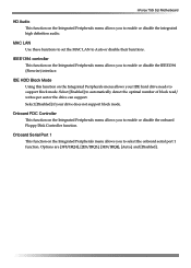
... function on the Integrated Peripherals menu allows you to enable or disable the integrated high definition audio. Select [Enabled] to Auto or disable their functions. nForce 750i SLI Motherboard HD Audio This function on the Integrated Peripherals menu allows you to enable or disable the onboard Floppy Disk Controller function.
... function on the Integrated Peripherals menu allows you to enable or disable the integrated high definition audio. Select [Enabled] to Auto or disable their functions. nForce 750i SLI Motherboard HD Audio This function on the Integrated Peripherals menu allows you to enable or disable the onboard Floppy Disk Controller function.
User Manual
Page 38
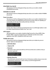
... KB Power ON Password function is enabled so that you must select a keyboard key as the timing hardware for multimedia and other time-sensitive application. nForce 750i SLI Motherboard WOL(PME#) From Soft-Off This function on the Power Management Setup menu allows you to enable or disable WOR(RI#) from soft-off . POWER...
... KB Power ON Password function is enabled so that you must select a keyboard key as the timing hardware for multimedia and other time-sensitive application. nForce 750i SLI Motherboard WOL(PME#) From Soft-Off This function on the Power Management Setup menu allows you to enable or disable WOR(RI#) from soft-off . POWER...
