EVGA 132-LF-E655-KR Support Question
EVGA 132-LF-E655-KR Support Question
Find answers below for this question about EVGA 132-LF-E655-KR - P55 Motherboard - ATX.Need a EVGA 132-LF-E655-KR manual? We have 2 online manuals for this item!
Question posted by slade9000 on April 7th, 2012
Power Supply
i just bought a new power supply gamer pro series 975w CP-GP975... i connected everything as it should be, but when i turned it on it only turned on for 2 seconds then it turned off and it just kept doing the same thing over and over... is it the power supply or did connect everything wrong. can you please guide me through it..
thankyou
Current Answers
Related EVGA 132-LF-E655-KR Manual Pages
User Guide - Page 1
User's Guide
EVGA P55 SLI Motherboard
User Guide - Page 3
...EVGA P55 SLI Motherboard 8
Motherboard Specifications 8 Hardware Installation 10
Safety Instructions 10 Preparing the Motherboard 11
Installing the CPU 11 Installing the CPU Fan 12 Installing System Memory (DIMMs 13 Installing the Motherboard 13 Installing the I/O Shield 14 Securing the Motherboard into a System Case 15 Connecting Cables 15
24-pin ATX Power (PW1 16 8-pin ATX 12V Power...
User Guide - Page 5
... CPU Configuration 40 Installing Drivers and Software 41 Windows XP/Vista/7 Driver Installation 41 Appendix A. EVGA P55 SLI Motherboard
Palette Snooping 35 PCI IDE BusMaster 35 OffBoard PCI/ISA IDE Card 35 Boot Configuration Features 36 Boot Device Priority 36 Hard Disk Drives 36 Power Management Features 37 ACPI Configuration 37 SLP_S4# Min.
User Guide - Page 6
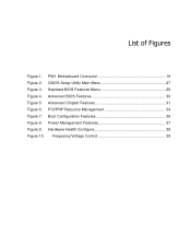
...Advanced Chipset Features 31 Figure 6. Boot Configuration Features 36 Figure 8. CMOS Setup Utility Main Menu 27 Figure 3. PCI/PNP Resource Management 34 Figure 7. PW1 Motherboard Connector 16 Figure 2. Power Management Features 37 Figure 9. Hardware Health Configure 38 Figure 10. List of Figures
Figure 1. Frequency/Voltage Control 39 Advanced BIOS Features 30 Figure 5.
User Guide - Page 7
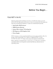
... purchased all the hardware necessary to allow for proper system functionality. For a full list of supported CPU's on this motherboard, please visit http://www.evga.com/support/motherboard/. When replacing a motherboard in the Kit
This kit contains all the necessary parts needed to install and connect your new EVGA P55 SLI Motherboard. EVGA P55 SLI Motherboard
Before You Begin...
User Guide - Page 8
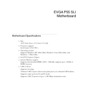
EVGA P55 SLI Motherboard
Motherboard Specifications
Size ATX form factor of DDR3 memory. USB 2.0 Ports Supports hot plug Thirteen USB 2.0 ... Windows XP 32bit/64bit, Windows Vista 32bit/64bit, and Windows 7 32bit/64bit
Intel P55 Express Chipset System Memory support
Supports dual channel DDR3-1600+. Officially supports up to a 480 Mbps transmission rate
User Guide - Page 10
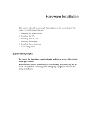
...; Installing the CPU Installing the CPU fan Installing the memory Installing the motherboard Connecting cables
Safety Instructions
To reduce the risk of the motherboard. Remember to remove power off your computer by disconnecting the AC main source before removing or installing any equipment from/to the computer chassis. Hardware Installation...
User Guide - Page 11
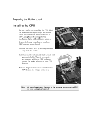
... up motion. Use the following procedure to install the CPU onto the motherboard:
Unhook the socket lever by the edges and do not touch the contacts on the motherboard or CPU. Remove the protective socket cover from the socket.
There is... have a safe place to the motherbard pins will automatically lift. Preparing the Motherboard
Installing the CPU
Be very careful when handling the CPU.
User Guide - Page 12
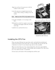
Carefully close and latch the lever. Align notches with this motherboard. The other holes are to be used with notches on the CPU
Load plate tip under the shoulder screw cap. Please note that can be ...
User Guide - Page 13
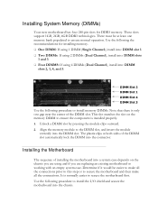
...DIMM into a system case depends on the memory DIMM to secure the motherboard and then make all the connections prior to this step or to ensure the component is installed properly.... DIMMs. Note that there is normally easier to ensure normal operation. Installing System Memory (DIMMs)
Your new motherboard has four 240-pin slots for installing memory. One DIMM: If using 1 DIMM (Single...
User Guide - Page 14
Before installing the motherboard, install the I /O shield into place and make sure it fits securely. Press the I /O shield from dust and foreign objects, and promotes correct airflow within the chassis. Installing the I/O Shield
The motherboard kit comes with an I/O shield that is used to block radio frequency transmissions, protects internal components from the inside of the chassis.
User Guide - Page 15
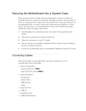
This will include: Power Connections
24-pin ATX power (PW1) 8-pin ATX 12V power (PW12) Internal Headers Front panel IEEE .... 4. Secure the motherboard with the stand offs. 3. Connecting Cables
This section takes you remove that the fan assembly is recommended to secure the motherboard using a minimum of nine (9) screws.
Securing the Motherboard into a System Case...
User Guide - Page 16
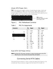
... 19 GND 20 RSVD 21 +5V 22 +5V 23 +5V 24 GND
8-pin ATX 12V Power (PW12)
PW12, the 8-pin ATX 12V power connection, is used to connect the Serial ATA II device to the CPU. 24-pin ATX Power (PW1)
PW1 is the main power supply connector located along the edge of the board next to PW1
Figure 1.
PW1...
User Guide - Page 17
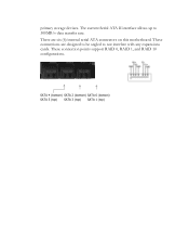
SATA 4 (bottom) SATA 2 (bottom) SATA 0 (bottom) SATA 5 (top) SATA 3 (top) SATA 1 (top) primary storage devices. These connections are six (6) internal serial ATA connectors on this motherboard. These connection points support RAID 0, RAID 1, and RAID 10 configurations. There are designed to be angled to 300MB/s data transfer rate. The current Serial ATA II interface ...
User Guide - Page 18
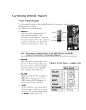
... Connecting Internal Headers
Front Panel Header
The front panel header on this motherboard is one connector used to connect the following four cables. (see Table 2 for pin definitions):
PWRLED
Attach the front panel power LED... to these two pins. When the system is turned on, the LED is pressed. Pressing the power button on the front panel turns the system on and off . The HDD indicator...
User Guide - Page 19
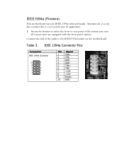
... system cases are equipped with the front panel option). Table 3.
Secure the bracket to the IEEE1394a header on the motherboard. IEEE1394a (Firewire)
This motherboard has one IEEE 1394a onboard header. Alternatively, you can also connect this to your system case (if applicable).
1.
IEEE 1394a Connector Pins
Connector IEEE 1394a Connector
10
9
8
7
6
5
4
3
2
1
Pin Signal...
User Guide - Page 23
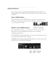
.... The RESET button with LED indicates the system's status.
Clear CMOS Button
The motherboard uses the CMOS RAM to easily reset the system, turn on /off the system.
These buttons allow you to store all the set parameters. Onboard Buttons
These onboard buttons include RESET, POWER and Clear CMOS. When the system is...
User Guide - Page 24
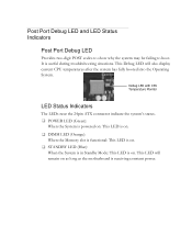
This Debug LED will remain on as long as the motherboard is receiving constant power. It is on . STANDBY LED (Blue):
When the System is in ...
Debug LED with CPU Temperature Monitor
LED Status Indicators
The LEDs near the 24pin ATX connector indicate the system's status. POWER LED (Green):
When the System is powered on: This LED is on. DIMM LED (Orange):
When the ...
User Guide - Page 41
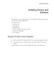
... CD does not run, go to open. Insert the Intel P55 installation CD for the motherboard included in the kit. 6. The CD will autorun, install ...the install
screen. Configuring the BIOS
Installing Drivers and Software
The CD that has been shipped with the EVGA P55 SLI Motherboard contains the following software and drivers: Chipset Drivers Audio drivers LAN Drivers &#...
User Guide - Page 42
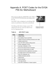
... are displayed on the Debug LED readout located directly onboard the motherboard. Check Battery Power and CMOS Initialize interrupt controlling hardware/vector table Initialize system timer...and set up application processors Re-enable cache for the EVGA P55 SLI Motherboard during system boot up. POST Codes for the EVGA P55 SLI Motherboard
This section provides the AMI POST Codes (Table 6) for ...
Similar Questions

Keep Restarting
Dear sir, Please i need your support my mother Motherboards » EVGA 132-BL-E758-A1EVGA 132-BL-E7...
Dear sir, Please i need your support my mother Motherboards » EVGA 132-BL-E758-A1EVGA 132-BL-E7...
(Posted by LOOSHY1980 1 year ago)

No Signal From Gt610
I have installed a GT610 in my Dell Optiplex 780 SFF PC running Windows 7 to drive an Eizo graphics ...
I have installed a GT610 in my Dell Optiplex 780 SFF PC running Windows 7 to drive an Eizo graphics ...
(Posted by cliffarmstrong 8 years ago)

Im Needing The Wiring Diagram For The Evgfa Nforce 680sli Motherboard,&pwr Switc
(Posted by DOCAIN 9 years ago)

Resolution For Post Codes.
I just moved from the states to Japan and when I plugged in my computer and powered it up, I get one...
I just moved from the states to Japan and when I plugged in my computer and powered it up, I get one...
(Posted by HerkNav617 10 years ago)
What are the EVGA return procedures and refund policies?
I would like to return my motherboard to EVGA and get a refund. Is the return and refund process pre...
I would like to return my motherboard to EVGA and get a refund. Is the return and refund process pre...
(Posted by Anonymous-10420 14 years ago)