User Manual
Page 2
User Guide EVGA nForce 750i SLI Motherboard
User Guide EVGA nForce 750i SLI Motherboard
User Manual
Page 3
... vi Intentions of the Kit vi EVGA nForce 750i Motherboard 1 Motherboard Specifications 1 Motherboard Specifications continued 2 UnPacking and Parts Description 3 Equipment ...4 Motherboard Internal Connectors and Back Panel Connectors 5 I/O Panel description...6 Safety Instructions...6 Preparing the Motherboard 6 Hardware Installation 7 Installing the CPU and Fan 8 Installing Memory DIMMs 9 Installing the Motherboard 10 Installing the I/O Shield 10 Securing the Motherboard into the Chassis 10 Connecting...
... vi Intentions of the Kit vi EVGA nForce 750i Motherboard 1 Motherboard Specifications 1 Motherboard Specifications continued 2 UnPacking and Parts Description 3 Equipment ...4 Motherboard Internal Connectors and Back Panel Connectors 5 I/O Panel description...6 Safety Instructions...6 Preparing the Motherboard 6 Hardware Installation 7 Installing the CPU and Fan 8 Installing Memory DIMMs 9 Installing the Motherboard 10 Installing the I/O Shield 10 Securing the Motherboard into the Chassis 10 Connecting...
User Manual
Page 7
Graphics Card This motherboard supports 2-way SLI with the motherboard and all the hardware necessary to install and connect your specific configuration, go through the installation instructions, we are going to require for your new EVGA nForce® 750i SLI motherboard. Power Supply The power supply requirement... is dependent upon the power and the number of the GPUs you are going to install the motherboard into a PC case. To calculate the power you...
Graphics Card This motherboard supports 2-way SLI with the motherboard and all the hardware necessary to install and connect your specific configuration, go through the installation instructions, we are going to require for your new EVGA nForce® 750i SLI motherboard. Power Supply The power supply requirement... is dependent upon the power and the number of the GPUs you are going to install the motherboard into a PC case. To calculate the power you...
User Manual
Page 8
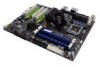
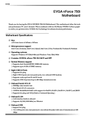
...: Supports Windows XP 32bit/64bit and Windows Vista 32bit/64bit Contains NVIDIA nForce 750i SLI MCP and SPP System Memory support Supports dual channel JEDEC DDR2-800 memory. This motherboard offers the tools and performance PC users' demand. Eight USB 2.0 Ports...port, one onboard header) with two SLI-Ready NVIDIA GeForce graphics cards, you for enhanced system performance. Motherboard Specifications Size ATX form factor of transmission at 400 Mbps EVGA EVGA nForce 750i Motherboard Thank you get innovative NVIDIA SLI Technology for buying the EVGA NFORCE 750i SLI Motherboard.
...: Supports Windows XP 32bit/64bit and Windows Vista 32bit/64bit Contains NVIDIA nForce 750i SLI MCP and SPP System Memory support Supports dual channel JEDEC DDR2-800 memory. This motherboard offers the tools and performance PC users' demand. Eight USB 2.0 Ports...port, one onboard header) with two SLI-Ready NVIDIA GeForce graphics cards, you for enhanced system performance. Motherboard Specifications Size ATX form factor of transmission at 400 Mbps EVGA EVGA nForce 750i Motherboard Thank you get innovative NVIDIA SLI Technology for buying the EVGA NFORCE 750i SLI Motherboard.

User Manual
Page 9
nForce 750i SLI Motherboard Onboard Audio Azalia High-Definition audio Supports 8-channel audio Supports S/PDIF output Supports Jack-Sensing function Green Function Supports ACPI (Advanced Configuration and Power Interface) Supports S0 (normal), S1 (power on suspend), S3 (suspend to RAM), S4 (Suspend to disk depends on OS), and S5 (soft - off) Expansion Slots Three PCI slots One PCI Express x1 slot Two PCI Express x16 Graphics slot compliant with PCI Express 2.0
nForce 750i SLI Motherboard Onboard Audio Azalia High-Definition audio Supports 8-channel audio Supports S/PDIF output Supports Jack-Sensing function Green Function Supports ACPI (Advanced Configuration and Power Interface) Supports S0 (normal), S1 (power on suspend), S3 (suspend to RAM), S4 (Suspend to disk depends on OS), and S5 (soft - off) Expansion Slots Three PCI slots One PCI Express x1 slot Two PCI Express x16 Graphics slot compliant with PCI Express 2.0
User Manual
Page 10
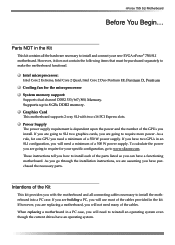
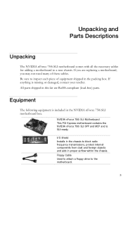
... from dust and foreign objects and aids in proper airflow within the chassis. Be sure to the motherboard. 3 NVIDIA nForce 750i SLI Motherboard This PCI Express motherboard contains the NVIDIA nForce 750i SLI SPP and MCP and is missing or damaged, contact your reseller. If you are RoHS-compliant (lead...-free) parts. All parts shipped in this kit are replacing a motherboard, you may not need many of equipment shipped in the NVIDIA nForce 750i SLI motherboard box. Equipment The following equipment is included in the packing box. Floppy Cable Used to attach...
... from dust and foreign objects and aids in proper airflow within the chassis. Be sure to the motherboard. 3 NVIDIA nForce 750i SLI Motherboard This PCI Express motherboard contains the NVIDIA nForce 750i SLI SPP and MCP and is missing or damaged, contact your reseller. If you are RoHS-compliant (lead...-free) parts. All parts shipped in this kit are replacing a motherboard, you may not need many of equipment shipped in the NVIDIA nForce 750i SLI motherboard box. Equipment The following equipment is included in the packing box. Floppy Cable Used to attach...

User Manual
Page 11
2-Port SATA Power Cable (Qty Three) 1394 Cable Provides two additional 1394 ports to either the front or back panels of the chassis. USB 2.0 4-Port Cable Provides four additional USB ports to the motherboard Comm2 Bracket Cable IDE-ATA 133 HDD Cable Driver Installation CD SLI Bridge 2-Way SATA Signal Cable (Qty Four) Used to support the Serial ATA protocol and each one connects a single drive to either the front or back panels of the chassis.
2-Port SATA Power Cable (Qty Three) 1394 Cable Provides two additional 1394 ports to either the front or back panels of the chassis. USB 2.0 4-Port Cable Provides four additional USB ports to the motherboard Comm2 Bracket Cable IDE-ATA 133 HDD Cable Driver Installation CD SLI Bridge 2-Way SATA Signal Cable (Qty Four) Used to support the Serial ATA protocol and each one connects a single drive to either the front or back panels of the chassis.

User Manual
Page 13
nForce 750i SLI Motherboard 1. Power button 19. Reset button 20. Azalia HD Audio Header 22. Chassis fan connector 11. Serial connector 12. Battery 13. Speaker 21. Backpanel connectors... Grey 7. IDE connector 6. Post port 10. Reset CMOS button 16. SPDIF connector 24. SPDIF output 6. Chassis fan2 connector 7. Chipset fan connector 1 7 2 3 4 5 6 4 4 Figure 2. EVGA nForce 750i SLI Backpanel connectors 1. CPU 775 Socket 2. Serial-ATA (SATA) connectors 9. Auxiliary fan connector 17. FP Audio connector 23. PCI Express x1 slot 28. PCI Express x16...
nForce 750i SLI Motherboard 1. Power button 19. Reset button 20. Azalia HD Audio Header 22. Chassis fan connector 11. Serial connector 12. Battery 13. Speaker 21. Backpanel connectors... Grey 7. IDE connector 6. Post port 10. Reset CMOS button 16. SPDIF connector 24. SPDIF output 6. Chassis fan2 connector 7. Chipset fan connector 1 7 2 3 4 5 6 4 4 Figure 2. EVGA nForce 750i SLI Backpanel connectors 1. CPU 775 Socket 2. Serial-ATA (SATA) connectors 9. Auxiliary fan connector 17. FP Audio connector 23. PCI Express x1 slot 28. PCI Express x16...
User Manual
Page 14
EVGA Hardware Installation This section will guide you through the installation of fire, electric shock, and injury, always follows basic safety precautions. You need to purchase these components to the computer chassis. Preparing the Motherboard The motherboard shipped in this installation. 7 Remember to.../to complete this section are: Preparing the motherboard Installing the CPU Installing the CPU fan Installing the memory Installing the motherboard Connecting cables and setting switches Safety Instructions To reduce the risk of the motherboard. The topics covered in the box does ...
EVGA Hardware Installation This section will guide you through the installation of fire, electric shock, and injury, always follows basic safety precautions. You need to purchase these components to the computer chassis. Preparing the Motherboard The motherboard shipped in this installation. 7 Remember to.../to complete this section are: Preparing the motherboard Installing the CPU Installing the CPU fan Installing the memory Installing the motherboard Connecting cables and setting switches Safety Instructions To reduce the risk of the motherboard. The topics covered in the box does ...

User Manual
Page 15
...tilting or sliding it . 5. Remove the processor from its protective cover, making sure you have a safe place to install the CPU onto the motherboard. 1. Align the notches in the socket. Make sure not to bend or break any pins on the load plate to protect the socket when there... came with the notches on the CPU 7. Lift the load plate. Note: Make sure the CPU is a protective socket cover on the back. nForce 750i SLI Motherboard Installing the CPU Be very careful when handling the CPU. There is fully seated and level in the processor with you close and engage the...
...tilting or sliding it . 5. Remove the processor from its protective cover, making sure you have a safe place to install the CPU onto the motherboard. 1. Align the notches in the socket. Make sure not to bend or break any pins on the load plate to protect the socket when there... came with the notches on the CPU 7. Lift the load plate. Note: Make sure the CPU is a protective socket cover on the back. nForce 750i SLI Motherboard Installing the CPU Be very careful when handling the CPU. There is fully seated and level in the processor with you close and engage the...

User Manual
Page 16
... pressing the module clips outward. 2. There must be at both sides of the memory slots.) One DIMM: Install into the DIMM slot. EVGA Installing Memory DIMMs Your new motherboard has four 1.8V 240-pin slots for the location of the DIMM slot automatically lock the DIMM into any slot, however, slot 0 is...
... pressing the module clips outward. 2. There must be at both sides of the memory slots.) One DIMM: Install into the DIMM slot. EVGA Installing Memory DIMMs Your new motherboard has four 1.8V 240-pin slots for the location of the DIMM slot automatically lock the DIMM into any slot, however, slot 0 is...

User Manual
Page 17
...from the inside the chassis. 2. Align the mounting holes with a mounting hole on the covers. Align the connectors to secure the motherboard and then make sure it is used to prevent the possibility of a short circuit. Determine if it is aligned with the chassis vents... the I /O shield. 4. In most cases, it would need to obtain the proper size from the chassis supplier. nForce 750i SLI Motherboard Installing the Motherboard The sequence of installing the motherboard into the chassis depends on the chassis you are using a minimum of nine (9) spacers. 1. Ensure that the fan ...
...from the inside the chassis. 2. Align the mounting holes with a mounting hole on the covers. Align the connectors to secure the motherboard and then make sure it is used to prevent the possibility of a short circuit. Determine if it is aligned with the chassis vents... the I /O shield. 4. In most cases, it would need to obtain the proper size from the chassis supplier. nForce 750i SLI Motherboard Installing the Motherboard The sequence of installing the motherboard into the chassis depends on the chassis you are using a minimum of nine (9) spacers. 1. Ensure that the fan ...

User Manual
Page 18
EVGA Connecting Cables and Setting Switches This section takes you through all the connections and switch settings necessary on page 4 to locate the connectors referenced in the following procedure. 10 This will include: Power Connections 24-pin ATX power 8-pin ATX 12V power Internal Headers Front panel IEEE 1394a USB headers Audio Speaker COM FDD IDE Serial ATA II Chassis Fans Rear panel USB 2.0 Adapter Expansion slots See Figure 1 on the motherboard.
EVGA Connecting Cables and Setting Switches This section takes you through all the connections and switch settings necessary on page 4 to locate the connectors referenced in the following procedure. 10 This will include: Power Connections 24-pin ATX power 8-pin ATX 12V power Internal Headers Front panel IEEE 1394a USB headers Audio Speaker COM FDD IDE Serial ATA II Chassis Fans Rear panel USB 2.0 Adapter Expansion slots See Figure 1 on the motherboard.

User Manual
Page 19
Make sure that the power supply cable and pins are properly aligned with the connector on the motherboard. v Pin Assignments Connector Pin Signal 1 +3.3V 2 +3.3V 3 GND 4 +5V 5 GND 6 +5V 7 GND 8 PWROK 9 +5V_AUX 10 +12V 11 +12V 12 +3.3V Pin Signal 13 ...used to provide power to the CPU. v Pin Assignments Connector Pin Signal 1 GND 2 GND 3 GND 4 GND Pin Signal 5 +12V 6 +12V 7 +12V 8 +12V 11 nForce 750i SLI Motherboard Power Connections 24-pin ATX Power PWR1 is the main power supply connector located along the edge of the board next to the connector and...
Make sure that the power supply cable and pins are properly aligned with the connector on the motherboard. v Pin Assignments Connector Pin Signal 1 +3.3V 2 +3.3V 3 GND 4 +5V 5 GND 6 +5V 7 GND 8 PWROK 9 +5V_AUX 10 +12V 11 +12V 12 +3.3V Pin Signal 13 ...used to provide power to the CPU. v Pin Assignments Connector Pin Signal 1 GND 2 GND 3 GND 4 GND Pin Signal 5 +12V 6 +12V 7 +12V 8 +12V 11 nForce 750i SLI Motherboard Power Connections 24-pin ATX Power PWR1 is the main power supply connector located along the edge of the board next to the connector and...
User Manual
Page 20
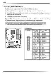
... connector to the hard disk documentation for the jumper settings. Connect the black connector (the cable with a single connector) to that of the slowest drive. EVGA Connecting IDE Hard Disk Drives The IDE connector supports Ultra ATA 133/100/66 IDE hard disk drives. 1. Note: If an ATA-66/100 disk... drive using any other IDE transfer protocol are attached to the same cable, the maximum transfer rate between the drives may be reduced to the motherboard. 2.
... connector to the hard disk documentation for the jumper settings. Connect the black connector (the cable with a single connector) to that of the slowest drive. EVGA Connecting IDE Hard Disk Drives The IDE connector supports Ultra ATA 133/100/66 IDE hard disk drives. 1. Note: If an ATA-66/100 disk... drive using any other IDE transfer protocol are attached to the same cable, the maximum transfer rate between the drives may be reduced to the motherboard. 2.

User Manual
Page 21
... RAID 5, RAID 0+1 and JBOD configurations. v Pin Assignments Connector SATA B1 SATA B0 SATA A0 (bottom) SATA A1 (top) Pin Signal 1 GND 2 TX+ 3 TX- 4 GND 5 RX+ 6 RX- 7 GND Connecting Floppy Disk Drive The motherboard supports a standard 360K, 720K, 1.2M, 1.44m, and a 2.88M floppy disk drive (FDD). The current ...26 Track 0 27 GND 28 Write Protect 29 NC 30 Read Data 31 GND 32 Side 1 Select 33 NC 34 Diskette Change nForce 750i SLI Motherboard Connecting Serial ATA Cables The Serial ATA II connector is used to connect the Serial ATA II device to 300MB/s data transfer rate....
... RAID 5, RAID 0+1 and JBOD configurations. v Pin Assignments Connector SATA B1 SATA B0 SATA A0 (bottom) SATA A1 (top) Pin Signal 1 GND 2 TX+ 3 TX- 4 GND 5 RX+ 6 RX- 7 GND Connecting Floppy Disk Drive The motherboard supports a standard 360K, 720K, 1.2M, 1.44m, and a 2.88M floppy disk drive (FDD). The current ...26 Track 0 27 GND 28 Write Protect 29 NC 30 Read Data 31 GND 32 Side 1 Select 33 NC 34 Diskette Change nForce 750i SLI Motherboard Connecting Serial ATA Cables The Serial ATA II connector is used to connect the Serial ATA II device to 300MB/s data transfer rate....

User Manual
Page 22
... connectors to the corresponding pins. Pressing the power button on the front panel turns the system on and off . EVGA Connecting Internal Headers Front Panel Header The front panel header on this motherboard is one connector used to connect the following four cables. (see Table 2 for pin definitions): PWRLED Attach the front...
... connectors to the corresponding pins. Pressing the power button on the front panel turns the system on and off . EVGA Connecting Internal Headers Front Panel Header The front panel header on this motherboard is one connector used to connect the following four cables. (see Table 2 for pin definitions): PWRLED Attach the front...
User Manual
Page 23
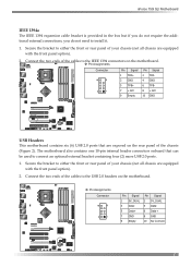
...+ 7 +12V 9 Empty Pin Signal 2 TPA4 GND 6 TPB8 +12V 10 GND USB Headers This motherboard contains six (6) USB 2.0 ports that can be used to the USB 2.0 headers on the motherboard. nForce 750i SLI Motherboard IEEE 1394a The IEEE 1394 expansion cable bracket is provided in the box but if you do not... require the additional external connections, you do not need to the IEEE 1394 connectors on the motherboard. Connect the two ends...
...+ 7 +12V 9 Empty Pin Signal 2 TPA4 GND 6 TPB8 +12V 10 GND USB Headers This motherboard contains six (6) USB 2.0 ports that can be used to the USB 2.0 headers on the motherboard. nForce 750i SLI Motherboard IEEE 1394a The IEEE 1394 expansion cable bracket is provided in the box but if you do not... require the additional external connections, you do not need to the IEEE 1394 connectors on the motherboard. Connect the two ends...

User Manual
Page 24
... to Send) 5 TXD (Transmit Data) 6 CTS (Clear to the other side of audio output choices: the Front Audio, the Rear Audio. EVGA Audio The audio connector supports HD audio standard and provides two kinds of the cable. v Pin Assignments Connector Pin Signal Pin Signal 1 PORT1_L 2 AUD_GND... 3 PORT1_R 4 PRECENCE_J 5 PORT2_R 6 SENSE1_RETURN 7 SENSE_SEND 8 Empty 9 PORT2_L 10 SENSE2_RETURN COM1 The motherboard kit provides an additional serial COM header for your machine. The front Audio supports re-tasking function.
... to Send) 5 TXD (Transmit Data) 6 CTS (Clear to the other side of audio output choices: the Front Audio, the Rear Audio. EVGA Audio The audio connector supports HD audio standard and provides two kinds of the cable. v Pin Assignments Connector Pin Signal Pin Signal 1 PORT1_L 2 AUD_GND... 3 PORT1_R 4 PRECENCE_J 5 PORT2_R 6 SENSE1_RETURN 7 SENSE_SEND 8 Empty 9 PORT2_L 10 SENSE2_RETURN COM1 The motherboard kit provides an additional serial COM header for your machine. The front Audio supports re-tasking function.

User Manual
Page 25
nForce 750i SLI Motherboard Fan Connections There are six fan connections on the motherboard. CHASSIS FAN2 NFORCE FAN: Install the fan over the nForce 750i SLI SPP to pins 1, 2, and 3 on the motherboard connector. SYS FAN AUX FAN CHASSIS FAN Others FAN: There are automatically turned off after the system enters S3, S4 and S5 mode. The fans ...
nForce 750i SLI Motherboard Fan Connections There are six fan connections on the motherboard. CHASSIS FAN2 NFORCE FAN: Install the fan over the nForce 750i SLI SPP to pins 1, 2, and 3 on the motherboard connector. SYS FAN AUX FAN CHASSIS FAN Others FAN: There are automatically turned off after the system enters S3, S4 and S5 mode. The fans ...
