User Manual
Page 3
... vi Intentions of the Kit vi EVGA nForce 750i Motherboard 1 Motherboard Specifications 1 Motherboard Specifications continued 2 UnPacking and Parts Description 3 Equipment ...4 Motherboard Internal Connectors and Back Panel Connectors 5 I/O Panel description...6 Safety Instructions...6 Preparing the Motherboard 6 Hardware Installation 7 Installing the CPU and Fan 8 Installing Memory DIMMs 9 Installing the Motherboard 10 Installing the I/O Shield 10 Securing the Motherboard into the Chassis 10 Connecting Cables...
... vi Intentions of the Kit vi EVGA nForce 750i Motherboard 1 Motherboard Specifications 1 Motherboard Specifications continued 2 UnPacking and Parts Description 3 Equipment ...4 Motherboard Internal Connectors and Back Panel Connectors 5 I/O Panel description...6 Safety Instructions...6 Preparing the Motherboard 6 Hardware Installation 7 Installing the CPU and Fan 8 Installing Memory DIMMs 9 Installing the Motherboard 10 Installing the I/O Shield 10 Securing the Motherboard into the Chassis 10 Connecting Cables...
User Manual
Page 4
... Setup 21 Main Menu...22 Standard CMOS Features Menu 22 Date and Time...23 IDE Channel and SATA Channel 23 Drive A...23 Halt On ...23 Memory ...23 Advanced BIOS Features 24 Removable Device Priority 24 Hard Disk Boot Priority 25 Quick Power On Self Test 25 First/Second/Third Boot Device...
... Setup 21 Main Menu...22 Standard CMOS Features Menu 22 Date and Time...23 IDE Channel and SATA Channel 23 Drive A...23 Halt On ...23 Memory ...23 Advanced BIOS Features 24 Removable Device Priority 24 Hard Disk Boot Priority 25 Quick Power On Self Test 25 First/Second/Third Boot Device...
User Manual
Page 6
PnP/PCI Configuration Menu 32 Init Display First 32 Reset Configuration Data 32 Resources Controlled By 33 IRQ Resources 33 PCI/VGA Palette Snoop 33 Maximum Payload Size 33 PC Health Status 34 Dynamic Fan Control 34 Frequency/Voltage Control 35 CPU Clock Ratio 35 LDT Frequency 35 System Clocks 35 FSB & Memory Config 36 FSB Memory Clock Mode 36 Memory Timing Settings 37 System Voltages 38 CPU Core ...38 CPU FSB...38 System Monitor Menu Installing Drivers and Software Driver Installation Appendix A. POST Codes
PnP/PCI Configuration Menu 32 Init Display First 32 Reset Configuration Data 32 Resources Controlled By 33 IRQ Resources 33 PCI/VGA Palette Snoop 33 Maximum Payload Size 33 PC Health Status 34 Dynamic Fan Control 34 Frequency/Voltage Control 35 CPU Clock Ratio 35 LDT Frequency 35 System Clocks 35 FSB & Memory Config 36 FSB Memory Clock Mode 36 Memory Timing Settings 37 System Voltages 38 CPU Core ...38 CPU FSB...38 System Monitor Menu Installing Drivers and Software Driver Installation Appendix A. POST Codes
User Manual
Page 7
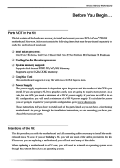
... number of the GPUs you will need a minimum of the parts listed so you need to require for your new EVGA nForce® 750i SLI motherboard. If you have two GPUs in a PC case, you are going to reinstall an operating system even though the ...have purchased the necessary parts. To calculate the power you will need many of a 500 W power supply. nForce 750i SLI Motherboard Before You Begin... As a rule, for the microprocessor System memory support: Supports dual channel DDR2 533/667/800, Memory. When replacing a motherboard in an SLI configuration, you install.
... number of the GPUs you will need a minimum of the parts listed so you need to require for your new EVGA nForce® 750i SLI motherboard. If you have two GPUs in a PC case, you are going to reinstall an operating system even though the ...have purchased the necessary parts. To calculate the power you will need many of a 500 W power supply. nForce 750i SLI Motherboard Before You Begin... As a rule, for the microprocessor System memory support: Supports dual channel DDR2 533/667/800, Memory. When replacing a motherboard in an SLI configuration, you install.
User Manual
Page 8
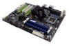
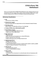
... 2 Extreme, Intel Core 2 Quad, Intel Core 2 Duo, Pentium EE, Pentium D, Pentium Operating systems: Supports Windows XP 32bit/64bit and Windows Vista 32bit/64bit Contains NVIDIA nForce 750i SLI MCP and SPP System Memory support Supports dual channel JEDEC DDR2-800 memory. EVGA EVGA nForce 750i Motherboard Thank you get innovative NVIDIA SLI Technology for buying the EVGA NFORCE 750i SLI Motherboard.
... 2 Extreme, Intel Core 2 Quad, Intel Core 2 Duo, Pentium EE, Pentium D, Pentium Operating systems: Supports Windows XP 32bit/64bit and Windows Vista 32bit/64bit Contains NVIDIA nForce 750i SLI MCP and SPP System Memory support Supports dual channel JEDEC DDR2-800 memory. EVGA EVGA nForce 750i Motherboard Thank you get innovative NVIDIA SLI Technology for buying the EVGA NFORCE 750i SLI Motherboard.
User Manual
Page 14
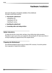
.... EVGA Hardware Installation This section will guide you through the installation of fire, electric shock, and injury, always follows basic safety precautions. Preparing the Motherboard The motherboard shipped in this installation. 7 The topics covered in the box does not contain a CPU or memory. ...source before removing or installing any equipment from/to complete this section are: Preparing the motherboard Installing the CPU Installing the CPU fan Installing the memory Installing the motherboard Connecting cables and setting switches Safety Instructions To reduce the risk of the...
.... EVGA Hardware Installation This section will guide you through the installation of fire, electric shock, and injury, always follows basic safety precautions. Preparing the Motherboard The motherboard shipped in this installation. 7 The topics covered in the box does not contain a CPU or memory. ...source before removing or installing any equipment from/to complete this section are: Preparing the motherboard Installing the CPU Installing the CPU fan Installing the memory Installing the motherboard Connecting cables and setting switches Safety Instructions To reduce the risk of the...

User Manual
Page 16
EVGA Installing Memory DIMMs Your new motherboard has four 1.8V 240-pin slots for installing memory. (See Figure 1 on the memory DIMM to not have the DIMMs in adjacent slots. Use the following procedure to install memory DIMMs. Note that there is only one memory bank populated to ensure normal operation. The idea is to ...slot on page 4 for the location of the DIMM slot automatically lock the DIMM into slot 0. There must be at both sides of the memory slots.) One DIMM: Install into the connector. The plastic clips at least one gap near the center of the DIMM slot. Use the ...
EVGA Installing Memory DIMMs Your new motherboard has four 1.8V 240-pin slots for installing memory. (See Figure 1 on the memory DIMM to not have the DIMMs in adjacent slots. Use the following procedure to install memory DIMMs. Note that there is only one memory bank populated to ensure normal operation. The idea is to ...slot on page 4 for the location of the DIMM slot automatically lock the DIMM into slot 0. There must be at both sides of the memory slots.) One DIMM: Install into the connector. The plastic clips at least one gap near the center of the DIMM slot. Use the ...

User Manual
Page 29
... menu to obtain improved performance for overclocking. PnP/PCI Configurations Use this menu to adjust various parameters to optimize system performance and configure clocks, voltages, memory timings, and more. Frequency/Voltage Control Use this menu to set up the basic system configuration. Power Management Setup Use this menu to modify the...
... menu to obtain improved performance for overclocking. PnP/PCI Configurations Use this menu to adjust various parameters to optimize system performance and configure clocks, voltages, memory timings, and more. Frequency/Voltage Control Use this menu to set up the basic system configuration. Power Management Setup Use this menu to modify the...
User Manual
Page 30
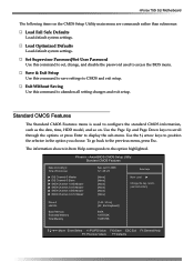
...:mm:ss) IDE Channel 0 Master IDE Channel 0 Slave SATA Channel 1 (A0) Master SATA Channel 2 (A1) Master SATA Channel 3 (B0) Master SATA Channel 4 (C1) Master Sat, Jul 01 2006 12 :...Help Main Level Change the day, month, year and century Drive A Halt On Base Memory Extended Memory Total Memory [1.44, 3.5 in the option you choose. Save & Exit Setup Use this command ...are commands rather than submenus: Load Fail Safe Defaults Load default system settings. nForce 750i SLI Motherboard The following items on . The information shown in Item Help corresponds to ...
...:mm:ss) IDE Channel 0 Master IDE Channel 0 Slave SATA Channel 1 (A0) Master SATA Channel 2 (A1) Master SATA Channel 3 (B0) Master SATA Channel 4 (C1) Master Sat, Jul 01 2006 12 :...Help Main Level Change the day, month, year and century Drive A Halt On Base Memory Extended Memory Total Memory [1.44, 3.5 in the option you choose. Save & Exit Setup Use this command ...are commands rather than submenus: Load Fail Safe Defaults Load default system settings. nForce 750i SLI Motherboard The following items on . The information shown in Item Help corresponds to ...
User Manual
Page 33
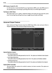
... option reduces the EMI generated by the LDT. Use the Page Up and Page Down keys to the operating system. The options are Disabled, Enabled. EVGA MPS Version Control For OS Use this function to select the Multi-Processor Specification (MPS) version that BIOS passes to scroll through the options. Phoenix... toggle between Enable and Disable Advanced Chipset Features Select Advanced Chipset Features from the CMOS Setup Utility menu and press Enter to be cached in memory for faster execution.
... option reduces the EMI generated by the LDT. Use the Page Up and Page Down keys to the operating system. The options are Disabled, Enabled. EVGA MPS Version Control For OS Use this function to select the Multi-Processor Specification (MPS) version that BIOS passes to scroll through the options. Phoenix... toggle between Enable and Disable Advanced Chipset Features Select Advanced Chipset Features from the CMOS Setup Utility menu and press Enter to be cached in memory for faster execution.
User Manual
Page 40
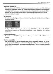
... the original PC AT Bus specification. Select [Auto(ESCD)] if you can manually select IRQ, DMA, and memory base address fields. IRQ Resources To enable this field enabled, press Enter to see options. nForce 750i SLI Motherboard Resources Controlled By This function on the PnP/PCI Configuration menu allows you to enable or disable the...
... the original PC AT Bus specification. Select [Auto(ESCD)] if you can manually select IRQ, DMA, and memory base address fields. IRQ Resources To enable this field enabled, press Enter to see options. nForce 750i SLI Motherboard Resources Controlled By This function on the PnP/PCI Configuration menu allows you to enable or disable the...
User Manual
Page 41
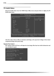
AwardBIOS CMOS Setup Utility PC Health Status Dynamic Fan Control CPU CPU VID CPU FSB Memory +3.3V +3.3V Dual +12V +5V +Vbat CPU Fan Speed Aux Fan Speed nForce Fan Speed Chassis Fan2 Speed 0 RPM [Press Enter] 47ºC/ 117ºF 1.28V 1.19V 1.90V 3.26V 3.26V 12.08V 4.93V 3.00V 4272 RPM 4891... Speed Control x Manual Fan Speed, % [Auto] 100% Dynamic Fan Control How effective Smart CPU Fan is will depend on fan design. EVGA PC Health Status Select PC Health Status from the CMOS Setup Utility menu and press Enter to display the PC Health Status menu. Most fans ...
AwardBIOS CMOS Setup Utility PC Health Status Dynamic Fan Control CPU CPU VID CPU FSB Memory +3.3V +3.3V Dual +12V +5V +Vbat CPU Fan Speed Aux Fan Speed nForce Fan Speed Chassis Fan2 Speed 0 RPM [Press Enter] 47ºC/ 117ºF 1.28V 1.19V 1.90V 3.26V 3.26V 12.08V 4.93V 3.00V 4272 RPM 4891... Speed Control x Manual Fan Speed, % [Auto] 100% Dynamic Fan Control How effective Smart CPU Fan is will depend on fan design. EVGA PC Health Status Select PC Health Status from the CMOS Setup Utility menu and press Enter to display the PC Health Status menu. Most fans ...

User Manual
Page 42
... the CMOS Setup Utility menu and press Enter to display the Frequency/Voltage Control menu. nForce 750i SLI Motherboard Frequency/Voltage Control Select Frequency/Voltage Control from 6 X through the options. AwardBIOS CMOS Setup Utility Frequency/Voltage Control System Clocks FSB & Memory Config System Voltages CPU Clock Ratio LDT Frequency [Press Enter] [Press Enter] [Press Enter...
... the CMOS Setup Utility menu and press Enter to display the Frequency/Voltage Control menu. nForce 750i SLI Motherboard Frequency/Voltage Control Select Frequency/Voltage Control from 6 X through the options. AwardBIOS CMOS Setup Utility Frequency/Voltage Control System Clocks FSB & Memory Config System Voltages CPU Clock Ratio LDT Frequency [Press Enter] [Press Enter] [Press Enter...
User Manual
Page 43
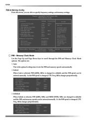
... [Disabled] [Disabled] [Disabled] Item Help Main Level "CPUOC MAX" realizes the complete optimized memory settings when SLI-Ready memory is changed , CPU Freq, MHz changes proportionally. FSB - The options are changed to specify ...frequency settings and memroy settings. As the FSB speed is installed Optimized memory settings by allowing X% CPU overclocking CPU overclocking may require manual overvolting of the CPU to scroll through the FSB and Memory Clock Mode options. EVGA...
... [Disabled] [Disabled] [Disabled] Item Help Main Level "CPUOC MAX" realizes the complete optimized memory settings when SLI-Ready memory is changed , CPU Freq, MHz changes proportionally. FSB - The options are changed to specify ...frequency settings and memroy settings. As the FSB speed is installed Optimized memory settings by allowing X% CPU overclocking CPU overclocking may require manual overvolting of the CPU to scroll through the FSB and Memory Clock Mode options. EVGA...
User Manual
Page 44
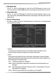
...CDM) Settings [Optimal] Auto(5) Auto(5) Auto(5) Auto(15) Auto(2T) Current Value 5 5 5 15 2T Item Help Main Level Select [Expert] to enter timings manually ** Advanced Memory Settings ** x tRRD Auto(3) x tRC Auto(23) x tWR Auto(5) x tWTR Auto(9) x tREF Auto 3 23 5 9 7.0uS :Move Enter:Select +/-/PU/PD:Value F10...reflects the actual frequency that takes effect when the system reboots. Phoenix - This is the minimum RAS# active time (options are 1 through 6). nForce 750i SLI Motherboard FSB (QDR), MHz Use the + or - w tRAS: This is the Precharge-to select Optimal.
...CDM) Settings [Optimal] Auto(5) Auto(5) Auto(5) Auto(15) Auto(2T) Current Value 5 5 5 15 2T Item Help Main Level Select [Expert] to enter timings manually ** Advanced Memory Settings ** x tRRD Auto(3) x tRC Auto(23) x tWR Auto(5) x tWTR Auto(9) x tREF Auto 3 23 5 9 7.0uS :Move Enter:Select +/-/PU/PD:Value F10...reflects the actual frequency that takes effect when the system reboots. Phoenix - This is the minimum RAS# active time (options are 1 through 6). nForce 750i SLI Motherboard FSB (QDR), MHz Use the + or - w tRAS: This is the Precharge-to select Optimal.
User Manual
Page 45
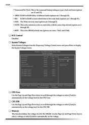
AwardBIOS CMOS Setup Utility System Voltages Parameters CPU Core CPU FSB Memory nForce SPP NF200 Voltage Level Settings Current Value [Auto] 1.28 [Auto] 1.20V ...tRC: RAS#-to -read delay with the same chip selected (options are Auto, 7.8uS, and 3.9uS). Memory This function defines the voltage level for the CPU Core. w tREF: This is the minimum write-to -... through the voltages or select [Auto] to -RAS# delay of the same bank (options are 2 through 7). EVGA w Command Per Clock: This is the command timing setting on a per clock unit basis (options are 1 through...
AwardBIOS CMOS Setup Utility System Voltages Parameters CPU Core CPU FSB Memory nForce SPP NF200 Voltage Level Settings Current Value [Auto] 1.28 [Auto] 1.20V ...tRC: RAS#-to -read delay with the same chip selected (options are Auto, 7.8uS, and 3.9uS). Memory This function defines the voltage level for the CPU Core. w tREF: This is the minimum write-to -... through the voltages or select [Auto] to -RAS# delay of the same bank (options are 2 through 7). EVGA w Command Per Clock: This is the command timing setting on a per clock unit basis (options are 1 through...

User Manual
Page 52
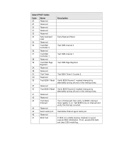
... PNP 25 Shadow VBIOS 26 Clock Gen 27 Setup BDA 28 Reserved 29 CPU Speed detect 2A Reserved 2B Init video 2C Reserved 2D Video memory test Description Test and Reset CMOS Load Chipset Defaults Initialize onboard clock generator CPU ID and initialize L1/L2 cache Initialize first 120 interrupt vectors... Shadow system/video BIOS Init onboard clock generator and sensor Setup BIOS DATA AREA (BDA) Chipset programming and CPU Speed detect Initialize Video Test Video Memory and display Logos
... PNP 25 Shadow VBIOS 26 Clock Gen 27 Setup BDA 28 Reserved 29 CPU Speed detect 2A Reserved 2B Init video 2C Reserved 2D Video memory test Description Test and Reset CMOS Load Chipset Defaults Initialize onboard clock generator CPU ID and initialize L1/L2 cache Initialize first 120 interrupt vectors... Shadow system/video BIOS Init onboard clock generator and sensor Setup BIOS DATA AREA (BDA) Chipset programming and CPU Speed detect Initialize Video Test Video Memory and display Logos
User Manual
Page 53
... interrupt and verify the interrupt occurred. If not, execute ISA tests and clear EISA mode flag. Reinitialize Preboot agent serial port If EISA non-volatile memory checksum is on the interrupt lines. Award POST Codes Code 2E Name Reserved 2F Reserved 30 Reserved 31 Reserved 32 Reserved 33 Early keyboard reset...
... interrupt and verify the interrupt occurred. If not, execute ISA tests and clear EISA mode flag. Reinitialize Preboot agent serial port If EISA non-volatile memory checksum is on the interrupt lines. Award POST Codes Code 2E Name Reserved 2F Reserved 30 Reserved 31 Reserved 32 Reserved 33 Early keyboard reset...
User Manual
Page 54
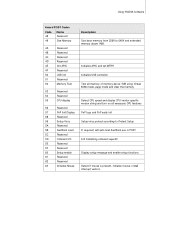
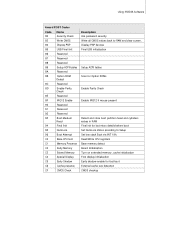
... Reserved 4B Reserved 4C Reserved 4D Reserved 4E Init APIC 4F Reserved 50 USB init 51 Reserved 52 Memory Test 53 Reserved 54 Reserved 55 CPU display 56 Reserved 57 PnP Init Display 58 Reserved 59 Setup Virus 5A Reserved 5B Awdflash Load 5C... Reserved 5F Reserved 60 Setup enable 61 Reserved 62 Reserved 63 Initialize Mouse Description Size base memory from 256K to 640K and extended memory above 1MB using Virtual 8086 mode, page mode and clear the memory Detect CPU speed and display CPU vendor specific version string and turn on all necessary CPU ...
... Reserved 4B Reserved 4C Reserved 4D Reserved 4E Init APIC 4F Reserved 50 USB init 51 Reserved 52 Memory Test 53 Reserved 54 Reserved 55 CPU display 56 Reserved 57 PnP Init Display 58 Reserved 59 Setup Virus 5A Reserved 5B Awdflash Load 5C... Reserved 5F Reserved 60 Setup enable 61 Reserved 62 Reserved 63 Initialize Mouse Description Size base memory from 256K to 640K and extended memory above 1MB using Virtual 8086 mode, page mode and clear the memory Detect CPU speed and display CPU vendor specific version string and turn on all necessary CPU ...
User Manual
Page 56
...92 Reserved 93 Boot Medium Read 94 Final Init 95 NumLock 96 Boot Attempt C0 Base CPU test C1 Memory Presence C2 Early Memory C3 Extend Memory C4 Special Display C5 Early Shadow C6 Cache presence CF CMOS Check Description Ask password security. Read/Write ...CPU registers Base memory detect Board Initialization Turn on extended memory, cache initialization First display initialization Early shadow enable for last micro details before boot Set NumLock status according ...
...92 Reserved 93 Boot Medium Read 94 Final Init 95 NumLock 96 Boot Attempt C0 Base CPU test C1 Memory Presence C2 Early Memory C3 Extend Memory C4 Special Display C5 Early Shadow C6 Cache presence CF CMOS Check Description Ask password security. Read/Write ...CPU registers Base memory detect Board Initialization Turn on extended memory, cache initialization First display initialization Early shadow enable for last micro details before boot Set NumLock status according ...