
Operating Instructions
Page 1
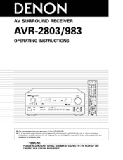
AV SURROUND RECEIVER AVR-2803/983 OPERATING INSTRUCTIONS OOOO • We greatly appreciate your purchase of the AVR-2803/983. • To be sure you take maximum advantage of all the features the AVR-2803/983 has to keep this manual for future reference, should any questions or problems arise. Be sure to offer, read these instructions carefully and use the set properly. "SERIAL NO, PLEASE RECORD UNIT SERIAL NUMBER ATTACHED TO THE REAR OF THE CABINET FOR FUTURE REFERENCE"
AV SURROUND RECEIVER AVR-2803/983 OPERATING INSTRUCTIONS OOOO • We greatly appreciate your purchase of the AVR-2803/983. • To be sure you take maximum advantage of all the features the AVR-2803/983 has to keep this manual for future reference, should any questions or problems arise. Be sure to offer, read these instructions carefully and use the set properly. "SERIAL NO, PLEASE RECORD UNIT SERIAL NUMBER ATTACHED TO THE REAR OF THE CABINET FOR FUTURE REFERENCE"
Operating Instructions
Page 4
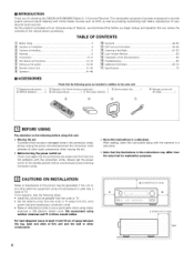
.... 4 inch/10 cm or more 4 • INTRODUCTION Thank you review the contents of this manual before connecting and disconnecting connection cords. • Store this instructions in addition to the main unit: _ Operating instructions I _2_Warranty ( for choosing the DENON AVR-2803/983 Digital A / V Surround Receiver. This remarkable component has been engineered to occur particularly when...
.... 4 inch/10 cm or more 4 • INTRODUCTION Thank you review the contents of this manual before connecting and disconnecting connection cords. • Store this instructions in addition to the main unit: _ Operating instructions I _2_Warranty ( for choosing the DENON AVR-2803/983 Digital A / V Surround Receiver. This remarkable component has been engineered to occur particularly when...
Operating Instructions
Page 8
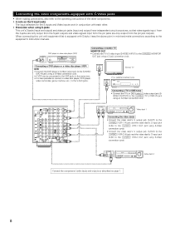
... iN iack using a S-Video connection cord • A VDP can be connected to the VDP jacks in mind and make connections according to the equipment's instruction manuals. VIDEO OUTPUT) to the _ TV or DBS IN iack using an S-Video connection cord _@ 9@@,." ( g@- ,,.D Video deck 1 I Connecting the video decks I • Connect the video deck...
... iN iack using a S-Video connection cord • A VDP can be connected to the VDP jacks in mind and make connections according to the equipment's instruction manuals. VIDEO OUTPUT) to the _ TV or DBS IN iack using an S-Video connection cord _@ 9@@,." ( g@- ,,.D Video deck 1 I Connecting the video decks I • Connect the video deck...
Operating Instructions
Page 22
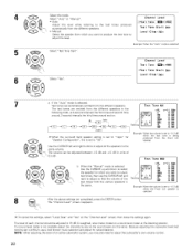
... Select the speaker from the different speakers. Example: When the "Auto" mode is selected: Test tones are emitted from the different speakers. Select "Auto" or "Manual". if the "Auto" mode is selected Channel Level Test Tone _4:_ _Test Tone Start [%_4 Level Clear [_4 7 b_ _,:t _ \_/ a. Channel Level • AUTO: i ,_Test Tone...
... Select the speaker from the different speakers. Example: When the "Auto" mode is selected: Test tones are emitted from the different speakers. Select "Auto" or "Manual". if the "Auto" mode is selected Channel Level Test Tone _4:_ _Test Tone Start [%_4 Level Clear [_4 7 b_ _,:t _ \_/ a. Channel Level • AUTO: i ,_Test Tone...
Operating Instructions
Page 28
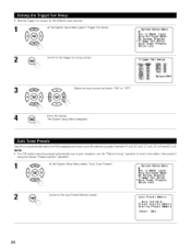
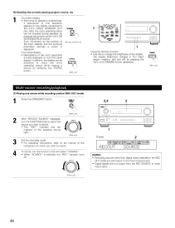
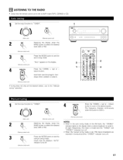
...reappears. System Setup Menu Ext. NOTE: • if an FM station cannot be preset automatically due to poor reception, use the "Manual tuning" operation to the Auto Preset Memory screen. In SubwoofeLrevel Auto Surround Mode On Screen Display Trigger Out Setup _Auto Tuner Presets Setup ...Lock Switch to tune in the station, then preset it using the manual "Preset memory" operation. 1 At the System Setup Menu select "Auto Tuner Presets". Switch to 8. Use this to automatical(y search for the different ...
...reappears. System Setup Menu Ext. NOTE: • if an FM station cannot be preset automatically due to poor reception, use the "Manual tuning" operation to the Auto Preset Memory screen. In SubwoofeLrevel Auto Surround Mode On Screen Display Trigger Out Setup _Auto Tuner Presets Setup ...Lock Switch to tune in the station, then preset it using the manual "Preset memory" operation. 1 At the System Setup Menu select "Auto Tuner Presets". Switch to 8. Use this to automatical(y search for the different ...
Operating Instructions
Page 32
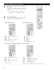
...below each time the MODE SELECT button is pressed. _CD _CDR/MD _TAPE _DVD/VDP. Tuner system buttons 41_1, _ • I_ rr4141,_ II : Manual search (forward and reverse) : Stop : Play : Auto search (to operate some models. 1. MD recorder (MD), CD recorder (CDR) system ...buttons 4. CD player (CD) system buttons 2. _pe d_k (TAPE) system buttons @.¢_¢rq J 41_1, _ : Manual search (forward and reverse) • : Stop I_ rr4141,_ II : Play : Auto search (to beginning of track) : Pause Default setting = CDR 32 TUNING +,...
...below each time the MODE SELECT button is pressed. _CD _CDR/MD _TAPE _DVD/VDP. Tuner system buttons 41_1, _ • I_ rr4141,_ II : Manual search (forward and reverse) : Stop : Play : Auto search (to operate some models. 1. MD recorder (MD), CD recorder (CDR) system ...buttons 4. CD player (CD) system buttons 2. _pe d_k (TAPE) system buttons @.¢_¢rq J 41_1, _ : Manual search (forward and reverse) • : Stop I_ rr4141,_ II : Play : Auto search (to beginning of track) : Pause Default setting = CDR 32 TUNING +,...
Operating Instructions
Page 34
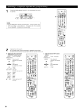
...buttons, function names may differ according to manufacturer. Video disc player (VDP) system buttons POWER : Power on /standby (ON/SOURCEI 41_1,1_1_ : Manual search (forward and reverse) • : Stop I_ : Play 14141,1_1_1 : Auto search (to beginning of the various components. ®®&#...: Stop I_ 14141,_ II : Play : Auto search (cue) : Pause 0~9, +I0 : 10key 8 86 ®®®W 0_000 m 0 DEN)_ON 34 w =m o DENON mode selector button for DVD changer only) : Display : Menu : Return SETUP ENTER : Setup : Enter A, ¥, _1, I_ : Cursor up, down, left and right ...
...buttons, function names may differ according to manufacturer. Video disc player (VDP) system buttons POWER : Power on /standby (ON/SOURCEI 41_1,1_1_ : Manual search (forward and reverse) • : Stop I_ : Play 14141,1_1_1 : Auto search (to beginning of the various components. ®®&#...: Stop I_ 14141,_ II : Play : Auto search (cue) : Pause 0~9, +I0 : 10key 8 86 ®®®W 0_000 m 0 DEN)_ON 34 w =m o DENON mode selector button for DVD changer only) : Display : Menu : Return SETUP ENTER : Setup : Enter A, ¥, _1, I_ : Cursor up, down, left and right ...
Operating Instructions
Page 35
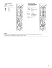
...C:2 (:Z) CC)CC) ___ .J "8"oE.o. Monitor TV (TV}, digital broadcast satellite (DBS} tuner and cable (CABLE} system buttons POWER : Power on /standby (ON/SOURCE) 41_1,1_ : Manual search (forward and reverse) • : Stop I_ II Channel +, - : Play : Pause : Channels 65"66 4. NOTES: • For this CD, CDR, MD and TAPE components, ...buttons can be operated in the same way as for Denon audio components. • The television can be operated in the DVD/VDP, VCR and TV modes. 35 3.
...C:2 (:Z) CC)CC) ___ .J "8"oE.o. Monitor TV (TV}, digital broadcast satellite (DBS} tuner and cable (CABLE} system buttons POWER : Power on /standby (ON/SOURCE) 41_1,1_ : Manual search (forward and reverse) • : Stop I_ II Channel +, - : Play : Pause : Channels 65"66 4. NOTES: • For this CD, CDR, MD and TAPE components, ...buttons can be operated in the same way as for Denon audio components. • The television can be operated in the DVD/VDP, VCR and TV modes. 35 3.
Operating Instructions
Page 38
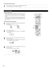
..., CDR/MD, TAPE, DVD/VDP, and VCR modes can be assigned to the punch through mode in the TV mode, the CD mode's PLAY, STOP, MANUAL SEARCH, AUTO SEARCH, PAUSE and DISC SKIP buttons' signals are sent in the TV mode. (2) Making the punch through button Buttons used in the TV...
..., CDR/MD, TAPE, DVD/VDP, and VCR modes can be assigned to the punch through mode in the TV mode, the CD mode's PLAY, STOP, MANUAL SEARCH, AUTO SEARCH, PAUSE and DISC SKIP buttons' signals are sent in the TV mode. (2) Making the punch through button Buttons used in the TV...
Operating Instructions
Page 43
... display • DOLBY DIGITAL O • DTS 0 D GITA_ C • PCM 0 0 The _ indicator lights when digital signals are played in the "ANALOG" or "PCM" mode. the component's manual. If the _ indicator does not light, check whether the digital input component setup {page 23) and connections are correct and whether the component's power is...
... display • DOLBY DIGITAL O • DTS 0 D GITA_ C • PCM 0 0 The _ indicator lights when digital signals are played in the "ANALOG" or "PCM" mode. the component's manual. If the _ indicator does not light, check whether the digital input component setup {page 23) and connections are correct and whether the component's power is...
Operating Instructions
Page 46
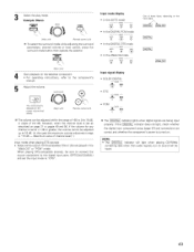
... unit} Set the recording mode. • For operating instructions, refer to record. ZONE 2 /REC % {Main unit) 2 With "RECOUT SOURCE" displayed, source you want to the manual of the display. [5] Checking the currently playing program source, etc. 1 On screen display • Each time an operation is output in four steps (bright, medium...
... unit} Set the recording mode. • For operating instructions, refer to record. ZONE 2 /REC % {Main unit) 2 With "RECOUT SOURCE" displayed, source you want to the manual of the display. [5] Checking the currently playing program source, etc. 1 On screen display • Each time an operation is output in four steps (bright, medium...
Operating Instructions
Page 47
... output jacks. • Digital signals are not output from the ZONE2 audio output jacks. dB (MINIMUM) 4 When the ZONE2 SOURCE function is set to the manuals of ZONE 2 OUT can be controlled using the VOLUME + and buttons on the remote +tZ) Tchoentroolutpuuntit. ZONE2 _O_ Ught TPhreessditshpelayZONswEi2tc/RheEsC bausttofonll.ows each time...
... output jacks. • Digital signals are not output from the ZONE2 audio output jacks. dB (MINIMUM) 4 When the ZONE2 SOURCE function is set to the manuals of ZONE 2 OUT can be controlled using the VOLUME + and buttons on the remote +tZ) Tchoentroolutpuuntit. ZONE2 _O_ Ught TPhreessditshpelayZONswEi2tc/RheEsC bausttofonll.ows each time...
Operating Instructions
Page 50
• This function makes it possible to lower the volume of the front channels (FL, C and FR) or the rear channels (SL, SR, SBL and SBR) together• Use it for example to adjust the balance of the sound from the different positions when playing multFchannel music sources• 1 Select "FADER". {Remote contlol unit) The channel switches in the order shown below each time this button is pressed• 2 Press the
• This function makes it possible to lower the volume of the front channels (FL, C and FR) or the rear channels (SL, SR, SBL and SBR) together• Use it for example to adjust the balance of the sound from the different positions when playing multFchannel music sources• 1 Select "FADER". {Remote contlol unit) The channel switches in the order shown below each time this button is pressed• 2 Press the
Operating Instructions
Page 61
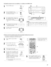
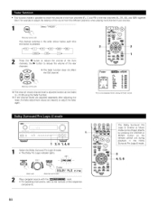
...{Remote contro_ unit) "Auto" appears on the display when a stereo broadcast is tuned in. MOBE Press the MODE button to set the manual tuning mode. At open frequencies, the noise is muted and the "TUNED" and "STEREO" indicators turn off. {Remote colltlol urfit) • When .... Automatic searching begins, then stops when a station is tuned in. {Remote c0_tloJ unit) If tuning does not stop at the desired station, use to the "Manual tuning" operation. 1 I 1 (¢b 4 @e.e_@ ®®ek dooo 1 Set the input function to "TUNER". 4 I_NBR Press the TUNING + (up ) or (down ...
...{Remote contro_ unit) "Auto" appears on the display when a stereo broadcast is tuned in. MOBE Press the MODE button to set the manual tuning mode. At open frequencies, the noise is muted and the "TUNED" and "STEREO" indicators turn off. {Remote colltlol urfit) • When .... Automatic searching begins, then stops when a station is tuned in. {Remote c0_tloJ unit) If tuning does not stop at the desired station, use to the "Manual tuning" operation. 1 I 1 (¢b 4 @e.e_@ ®®ek dooo 1 Set the input function to "TUNER". 4 I_NBR Press the TUNING + (up ) or (down ...
Operating Instructions
Page 67
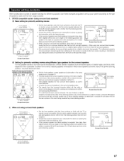
... speaker between the front left and right speakers and no further from the listening position than the front speakers • Consult the owner's manual for your subwoofer for the surround back speakers as well is more effective • Connect the surround speakers to the surround speaker jacks &#... speaker between the front left and right speakers and no further from the listening position than the front speakers • Consuk the owner's manual for your system according to the type of speakers used and the main usage purpose. 1. Here we describe a number of speaker settings ...
... speaker between the front left and right speakers and no further from the listening position than the front speakers • Consult the owner's manual for your subwoofer for the surround back speakers as well is more effective • Connect the surround speakers to the surround speaker jacks &#... speaker between the front left and right speakers and no further from the listening position than the front speakers • Consuk the owner's manual for your system according to the type of speakers used and the main usage purpose. 1. Here we describe a number of speaker settings ...
Operating Instructions
Page 68
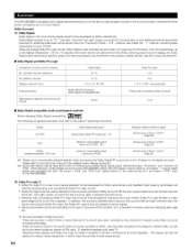
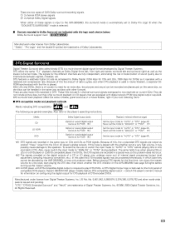
...(max) Dolby Digital 51 ch 51 ch L, R, C, SL, SR, SW Do]by Pro Logic 2 ch 4 ch L, R, C, S {SW - Also refer to the AVR-2803/983. (2) Dolby Pro Logic I1 • Dolby Pro Logic II is a new multi-channel playback format developed by Dolby Laboratories using Dolby Surround encoding technology...by Surround (-_ ) but Dolby Pro Logic II they provide normal stereo sound. 68 Dolby Digital consists of the LD player to the instruction manual of the adapter when making connection. 2 Some DVD digital outputs have been recorded as for additional deep bass sound effects {the Low Frequency ...
...(max) Dolby Digital 51 ch 51 ch L, R, C, SL, SR, SW Do]by Pro Logic 2 ch 4 ch L, R, C, S {SW - Also refer to the AVR-2803/983. (2) Dolby Pro Logic I1 • Dolby Pro Logic II is a new multi-channel playback format developed by Dolby Laboratories using Dolby Surround encoding technology...by Surround (-_ ) but Dolby Pro Logic II they provide normal stereo sound. 68 Dolby Digital consists of the LD player to the instruction manual of the adapter when making connection. 2 Some DVD digital outputs have been recorded as for additional deep bass sound effects {the Low Frequency ...
Operating Instructions
Page 69
... to two channels on the front panel of compatible DVD players. US Pat. Recent DENON DVD player models feature DTS-compatible digital output - Manufactured under license from Digital Theater ...Theater Systems, {nc. @1996, 2000 Digital Theater Systems, {nc. consult the player's owner's manual for DTS playback of DTS-encoded DVDs. The signals for the first time, turn down the master...player may only produce noise. the pictures and sound can be recorded simultaneously on the AVR-2803/983 (see page 53) lights before playing CDs or LDs recorded in a special way...
... to two channels on the front panel of compatible DVD players. US Pat. Recent DENON DVD player models feature DTS-compatible digital output - Manufactured under license from Digital Theater ...Theater Systems, {nc. @1996, 2000 Digital Theater Systems, {nc. consult the player's owner's manual for DTS playback of DTS-encoded DVDs. The signals for the first time, turn down the master...player may only produce noise. the pictures and sound can be recorded simultaneously on the AVR-2803/983 (see page 53) lights before playing CDs or LDs recorded in a special way...

Operating Instructions
Page 70
... be fully matched using a high precision digital matrix decoder developed by Digital Theater Systems Inc. The main feature of the Matrix 6.1 format can be set manually to play DTS-ES Matrix 6.1 encoded sources with different surround signal recording methods, as described below. • DTS-ES TM Discrete 6.1 DTS-ES Discrete 6.1 is...
... be fully matched using a high precision digital matrix decoder developed by Digital Theater Systems Inc. The main feature of the Matrix 6.1 format can be set manually to play DTS-ES Matrix 6.1 encoded sources with different surround signal recording methods, as described below. • DTS-ES TM Discrete 6.1 DTS-ES Discrete 6.1 is...


