
Operating Instructions
Page 4
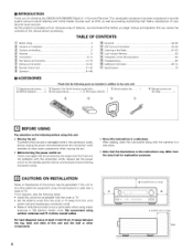
..., [] CAUTIONS ON INSTALLATION Noise or disturbance of the Microprocessor 63 Troubleshooting Additional Information 64 65~74 Specifications 75 • ACCESSORIES Check that there are included in addition to provide superb surround sound listening with the connection cords. We recommend using indoor antennas or 300 _/ohms feeder wires. This remarkable component has been engineered to the main unit: _ Operating instructions I _2_Warranty ( for choosing the DENON AVR-2803/983 Digital A / V Surround Receiver.
..., [] CAUTIONS ON INSTALLATION Noise or disturbance of the Microprocessor 63 Troubleshooting Additional Information 64 65~74 Specifications 75 • ACCESSORIES Check that there are included in addition to provide superb surround sound listening with the connection cords. We recommend using indoor antennas or 300 _/ohms feeder wires. This remarkable component has been engineered to the main unit: _ Operating instructions I _2_Warranty ( for choosing the DENON AVR-2803/983 Digital A / V Surround Receiver.
Operating Instructions
Page 5
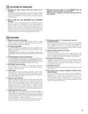
... 7.1 channel pre-amp outputs, controlled by Dolby Laboratories and Lucas Films and first used to another source (audio). 12.Future Sound Format Upgrade Capability via Eight Channel Inputs & Outputs For future muki-channel audio format(s), the AVR-2803/983 is the default digital audio delivery system for superior picture quality. 11.Video Select Function Allow you to watch one set -up to the type of this happens, either turn down the MASTER VOLUME control or connect components to 5.1 channels of regular stereo sources. 4. Wide screen mode...
... 7.1 channel pre-amp outputs, controlled by Dolby Laboratories and Lucas Films and first used to another source (audio). 12.Future Sound Format Upgrade Capability via Eight Channel Inputs & Outputs For future muki-channel audio format(s), the AVR-2803/983 is the default digital audio delivery system for superior picture quality. 11.Video Select Function Allow you to watch one set -up to the type of this happens, either turn down the MASTER VOLUME control or connect components to 5.1 channels of regular stereo sources. 4. Wide screen mode...
Operating Instructions
Page 6
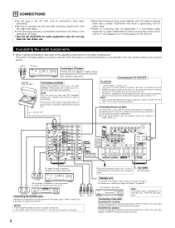
... [Connecting a tape deck] Connections for recording: Connect tile tape deck's recording fflpu_ iacks (LINE _N or REC) to this url_t's tape recording {CDR/TAPE OUT) jacks using pin plug cords 6 Incomplete connections will result in generating hum or other components. The power to these outlets is turned on and standby from the remote control unit driers, TVs ot other electrical appliances Connecting the pre-out jacks Use these iacks if you wish to connect external power amplifier...
... [Connecting a tape deck] Connections for recording: Connect tile tape deck's recording fflpu_ iacks (LINE _N or REC) to this url_t's tape recording {CDR/TAPE OUT) jacks using pin plug cords 6 Incomplete connections will result in generating hum or other components. The power to these outlets is turned on and standby from the remote control unit driers, TVs ot other electrical appliances Connecting the pre-out jacks Use these iacks if you wish to connect external power amplifier...
Operating Instructions
Page 9
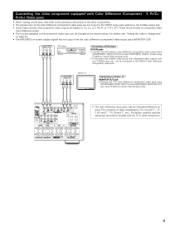
... INPUT) to the COMPONENT MONETOR OUT jack using 75 OJohms coaxiaE video pimplug cords¸ • The color difference input jacks may be changed at the system setup. VIDEO OUT DVD player +++++I+ Connecting a DVD player ] r++l++ ,DVD IN jacks • Connect the DVD player's color difference (component) video output iacks (COMPONENT VIDEO OUTPUT) to the COMPONENT VtDEO-I tN iack using 75 _dohms coaxial video pin-ptug cords¸ • In the same way, another video source with component video outputs are not output from the color difference {component) video output jacks {MONITOR...
... INPUT) to the COMPONENT MONETOR OUT jack using 75 OJohms coaxiaE video pimplug cords¸ • The color difference input jacks may be changed at the system setup. VIDEO OUT DVD player +++++I+ Connecting a DVD player ] r++l++ ,DVD IN jacks • Connect the DVD player's color difference (component) video output iacks (COMPONENT VIDEO OUTPUT) to the COMPONENT VtDEO-I tN iack using 75 _dohms coaxial video pin-ptug cords¸ • In the same way, another video source with component video outputs are not output from the color difference {component) video output jacks {MONITOR...

Operating Instructions
Page 12
... rear panel NOTE: NEVER touch the speaker ter minals when the power is on the screen may be changed to use of speakers with an impedance lower than the specified impedance are connected¸ 1 Loosen by turning counterclockwise 2 Insert the cord Connection the speaker terminals 3 lighten by the speaker's magnetism If this should happen, move the speaker away to the operating instructions of time at the same time, since use this effect ][ SURROUND SPEAKER...
... rear panel NOTE: NEVER touch the speaker ter minals when the power is on the screen may be changed to use of speakers with an impedance lower than the specified impedance are connected¸ 1 Loosen by turning counterclockwise 2 Insert the cord Connection the speaker terminals 3 lighten by the speaker's magnetism If this should happen, move the speaker away to the operating instructions of time at the same time, since use this effect ][ SURROUND SPEAKER...
Operating Instructions
Page 16
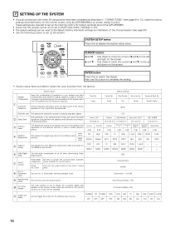
... subwoofer speaker for playing deep bass signals Delay %me This parameter is to be reset to the default {factory shipment) settings by initialization of the microprocessor (see pages 6 to switch the display. [] SETTING UP THE SYSTEM • Once all connections with which the bass sound of the slgnals output from the speakers and the frequency response Front Sp Large Crossover Ftequency Set the frequency (Hz) below on the monitor screen using the AVR-2803/983'S on the remote Auto Surround Mode...
... subwoofer speaker for playing deep bass signals Delay %me This parameter is to be reset to the default {factory shipment) settings by initialization of the microprocessor (see pages 6 to switch the display. [] SETTING UP THE SYSTEM • Once all connections with which the bass sound of the slgnals output from the speakers and the frequency response Front Sp Large Crossover Ftequency Set the frequency (Hz) below on the monitor screen using the AVR-2803/983'S on the remote Auto Surround Mode...
Operating Instructions
Page 17
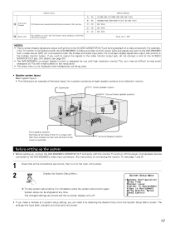
... NOTES: • The on -screen display function is completed, press the system setup button again. System Setup Menu _Speaker Configuration Delay Time Channel Level Digital In Assignment Video In Assignment Dolby Digital Setup Zone2 Control • if you can be changed settings are correct, then turn on screen display turns off the power of a video component. @ APuretosetTsuner _ Setup Lock System setup FM stations are received automatically and stored it1 the memory Set whether or not to lock tile system setup settlrlgs so that point...
... NOTES: • The on -screen display function is completed, press the system setup button again. System Setup Menu _Speaker Configuration Delay Time Channel Level Digital In Assignment Video In Assignment Dolby Digital Setup Zone2 Control • if you can be changed settings are correct, then turn on screen display turns off the power of a video component. @ APuretosetTsuner _ Setup Lock System setup FM stations are received automatically and stored it1 the memory Set whether or not to lock tile system setup settlrlgs so that point...
Operating Instructions
Page 18
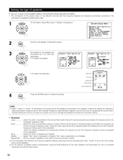
...When this is set, bass sound with a connected subwoofer will yield the best results. 18 • Set up in function of your speaker systems. Performing this setup optimizes the system. • The composition of the signals output to the different channels and the frequency response are adjusted automatically combination of speakers actually being used for the surround back channel. System Setup Menu 7Speaker Configuration Delay Time Channel Level Digital In Assignment Video In Assignment Dolby DlKital Setup Zone2 Control _,_ Switchtothespeakerconfigurationscreen. For the...
...When this is set, bass sound with a connected subwoofer will yield the best results. 18 • Set up in function of your speaker systems. Performing this setup optimizes the system. • The composition of the signals output to the different channels and the frequency response are adjusted automatically combination of speakers actually being used for the surround back channel. System Setup Menu 7Speaker Configuration Delay Time Channel Level Digital In Assignment Video In Assignment Dolby DlKital Setup Zone2 Control _,_ Switchtothespeakerconfigurationscreen. For the...
Operating Instructions
Page 24
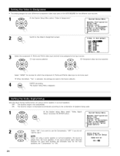
... sources. 1 At the System Setup Menu select "Video In Assignment". • This setting assigns the color difference (component} video input jacks of speakers being used . -_ When the default, "Yes", is NplOayTeEd: from the front speakers. The System Setup Menu reappears. 4 ENTER the setting. System Setup Menu Speaker Configuration Delay Time Channel Level Digital In Assignment zVideo In Assignment Dolby Digital Setup Zone2 Control 2 Switch to use the Compression, "OFF" if you do not Dolby Digital Downmix Option Setup When not using a center speaker or surround speakers...
... sources. 1 At the System Setup Menu select "Video In Assignment". • This setting assigns the color difference (component} video input jacks of speakers being used . -_ When the default, "Yes", is NplOayTeEd: from the front speakers. The System Setup Menu reappears. 4 ENTER the setting. System Setup Menu Speaker Configuration Delay Time Channel Level Digital In Assignment zVideo In Assignment Dolby Digital Setup Zone2 Control 2 Switch to use the Compression, "OFF" if you do not Dolby Digital Downmix Option Setup When not using a center speaker or surround speakers...
Operating Instructions
Page 42
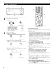
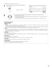
... AVR-2803/983'S surround decoder is selected, press the SOURCE button then operate the input function selector. 8OUROE (Main unit) 2 Select the input mode. • Selecting the analog mode Press the ANALOG button to switch to the digital input jacks are identified and decoding and playback are selected. NOTE: • Note that noise may be selected for all input sources other than PHONO and TUNER. IN button on the remote control unit) to play in the "PCM" {exclusive PCM signal playback} or "ANALOG" (exclusive PCM signal playback) mode...
... AVR-2803/983'S surround decoder is selected, press the SOURCE button then operate the input function selector. 8OUROE (Main unit) 2 Select the input mode. • Selecting the analog mode Press the ANALOG button to switch to the digital input jacks are identified and decoding and playback are selected. NOTE: • Note that noise may be selected for all input sources other than PHONO and TUNER. IN button on the remote control unit) to play in the "PCM" {exclusive PCM signal playback} or "ANALOG" (exclusive PCM signal playback) mode...
Operating Instructions
Page 43
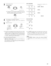
Select the play mode. the component's manual. Adjust the volume. However, when the channel level is set as descnbed on the input slgna_ Input signal display • DOLBY DIGITAL O • DTS 0 D GITA_ C • PCM 0 0 The _ indicator lights when digital signals are being input properly. SURROUND MO_E {Mainunit) S• taFrtorplaoypbearcaktingon thinestrsuecleticotnesd, cormepfeornentot. When playing DTS-compatible sources, be sure to connect the source component to the digital input jacks (OPTICAL/COAXIAL} and set at +1 dB or greater, the volume cannot be adjusted up to ...
Select the play mode. the component's manual. Adjust the volume. However, when the channel level is set as descnbed on the input slgna_ Input signal display • DOLBY DIGITAL O • DTS 0 D GITA_ C • PCM 0 0 The _ indicator lights when digital signals are being input properly. SURROUND MO_E {Mainunit) S• taFrtorplaoypbearcaktingon thinestrsuecleticotnesd, cormepfeornentot. When playing DTS-compatible sources, be sure to connect the source component to the digital input jacks (OPTICAL/COAXIAL} and set at +1 dB or greater, the volume cannot be adjusted up to ...
Operating Instructions
Page 45
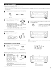
... the volume when using the VIDEO SELECT button and the FUNCTION knob. • Switch the program source to the component connected to the video input. 11 Display I]:H.....U i:d::iUF;:CEI I 45 UPrseessthistheswiVtcIhDEtOo mSoEnLitoErCTa s_.,_ button, turn off temporarily (MUTING) l ol • 1 1 NOTE: To prevent hearing loss, do not pass through the bass and treble adjustment circuits, providing higher quality sound. [2] Listening over headphones Pthleugjacthk.e headphones' plug into the PHONES jack. Press the MUTING button...
... the volume when using the VIDEO SELECT button and the FUNCTION knob. • Switch the program source to the component connected to the video input. 11 Display I]:H.....U i:d::iUF;:CEI I 45 UPrseessthistheswiVtcIhDEtOo mSoEnLitoErCTa s_.,_ button, turn off temporarily (MUTING) l ol • 1 1 NOTE: To prevent hearing loss, do not pass through the bass and treble adjustment circuits, providing higher quality sound. [2] Listening over headphones Pthleugjacthk.e headphones' plug into the PHONES jack. Press the MUTING button...
Operating Instructions
Page 51
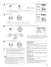
AFDM 4_ TSOBNECH t OUT 4NRML (OF F) ) [_ Yes_ TIlls is performed from the main unit or the remote control unit. SELECT "DOLBY PL II OPTIONS4 (Main unit) DispEay i,i0[::,E,::i (Remote control unit) i,i0[::,EDOLi..:iPML AFDM Set the surround parameter mode. 8URROLIND p,_%_IEIER 8um_o "DOLBY PL I I C I NEMA EQ. (Main unit) _u_'_ (Remote control unit) IDiOispDlayE c i The on-screen display differs according to whether the operation is the screen when operated with tile remote control unit 4 Select the play mode.
AFDM 4_ TSOBNECH t OUT 4NRML (OF F) ) [_ Yes_ TIlls is performed from the main unit or the remote control unit. SELECT "DOLBY PL II OPTIONS4 (Main unit) DispEay i,i0[::,E,::i (Remote control unit) i,i0[::,EDOLi..:iPML AFDM Set the surround parameter mode. 8URROLIND p,_%_IEIER 8um_o "DOLBY PL I I C I NEMA EQ. (Main unit) _u_'_ (Remote control unit) IDiOispDlayE c i The on-screen display differs according to whether the operation is the screen when operated with tile remote control unit 4 Select the play mode.
Operating Instructions
Page 54
LFE 4 OdBb TONE < [_ DS.BCOCMHP O4_UJkT "Dolby Digital EX CINEMA EQ. 4 SURROUND pie_MEIER 8tlBROUND P_AMEq_ Display the surround parameter _ _ menu. (Main unit} (Remote control unit) NOTE: The display on the screen differs depending on whether you are performing the operation from the main unit or the remote control unit.
LFE 4 OdBb TONE < [_ DS.BCOCMHP O4_UJkT "Dolby Digital EX CINEMA EQ. 4 SURROUND pie_MEIER 8tlBROUND P_AMEq_ Display the surround parameter _ _ menu. (Main unit} (Remote control unit) NOTE: The display on the screen differs depending on whether you are performing the operation from the main unit or the remote control unit.
Operating Instructions
Page 59
...: : Turn the control clockwise. (The bass or treble sound can be set in -phase component is assigned mainly to the center channel (C} and the reversed phase component to the surround (SL, SR and SB channels). • Music This mode is no loss of sound quality, and the effect of the surround signals output from the center (C} and surround (SL, SR and SB) channels add a natural sense of expansion to the sound field. There are played directly...
...: : Turn the control clockwise. (The bass or treble sound can be set in -phase component is assigned mainly to the center channel (C} and the reversed phase component to the surround (SL, SR and SB channels). • Music This mode is no loss of sound quality, and the effect of the surround signals output from the center (C} and surround (SL, SR and SB) channels add a natural sense of expansion to the sound field. There are played directly...
Operating Instructions
Page 61
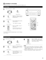
... RADIO • Check that the display's "AUTO" indicator turns off . MOBE Press the MODE button to set , FM stereo broadcasts are received in . {Remote c0_tloJ unit) If tuning does not stop at the desired station, use to the "Manual tuning" operation. 1 I 1 (¢b 4 @e.e_@ ®®ek dooo 1 Set the input function to select the desired band (AM or FM). NOTES: • When in the auto tuning mode on the FM band, the "STEREO" indicator lights...
... RADIO • Check that the display's "AUTO" indicator turns off . MOBE Press the MODE button to set , FM stereo broadcasts are received in . {Remote c0_tloJ unit) If tuning does not stop at the desired station, use to the "Manual tuning" operation. 1 I 1 (¢b 4 @e.e_@ ®®ek dooo 1 Set the input function to select the desired band (AM or FM). NOTES: • When in the auto tuning mode on the FM band, the "STEREO" indicator lights...
Operating Instructions
Page 64
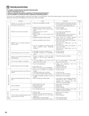
... stylus • Replace cartridge • Replace with MM cartridge or use a head amplifier or step-up to suitable level • Switch off MUTING • input digital signals or select input jacks to which digital signals are using headphones • Mute mode is set • Monitor TV not connected to AVR-2803/983 • Ground wire of turntable not connected properly • Incomplete PHONO jack connection • TV or radio transmission antenna nearby • Turntable and speaker systems too close...
... stylus • Replace cartridge • Replace with MM cartridge or use a head amplifier or step-up to suitable level • Switch off MUTING • input digital signals or select input jacks to which digital signals are using headphones • Mute mode is set • Monitor TV not connected to AVR-2803/983 • Ground wire of turntable not connected properly • Incomplete PHONO jack connection • TV or radio transmission antenna nearby • Turntable and speaker systems too close...
Operating Instructions
Page 68
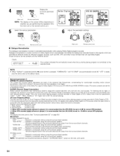
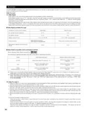
... Dolby Digital surround on stereo VCRs, as well as for PCM) Set the input mode to "AUTO" {Page 42) 1 Please use a commercially available adapter when connecting the Dolby Digital RF output jack of the LD player to the digital input jack. Unlike the analog Dolby Pro Logic format, Doiby Digital's main channels can all contain full range sound information, from noise and distortion. • Dolby Digital and Dolby Pro Logic Comparison of home surround systems No recorded channels (elements) No playback channels Playback channels (max) Dolby Digital...
... Dolby Digital surround on stereo VCRs, as well as for PCM) Set the input mode to "AUTO" {Page 42) 1 Please use a commercially available adapter when connecting the Dolby Digital RF output jack of the LD player to the digital input jack. Unlike the analog Dolby Pro Logic format, Doiby Digital's main channels can all contain full range sound information, from noise and distortion. • Dolby Digital and Dolby Pro Logic Comparison of home surround systems No recorded channels (elements) No playback channels Playback channels (max) Dolby Digital...
Operating Instructions
Page 69
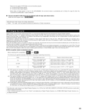
... cannot be sure to switch the input mode to "AUTO" or "DTS" before turning up the master volume. _3 A DVD player with other wodd-wide patents issued and pending. "DTS","DTS-ES Extended Surround" and "Neo:6" are trademarks of Dolby Laboratories. There are two types of DVD Dolby surround recording signals. _ 2-channel PCM stereo signals _2_ 2-channel Dolby Digital signals When either of these signals is input to the AVR-2803/983, the surround mode is automatically set at the digital outputs of a CD or...
... cannot be sure to switch the input mode to "AUTO" or "DTS" before turning up the master volume. _3 A DVD player with other wodd-wide patents issued and pending. "DTS","DTS-ES Extended Surround" and "Neo:6" are trademarks of Dolby Laboratories. There are two types of DVD Dolby surround recording signals. _ 2-channel PCM stereo signals _2_ 2-channel Dolby Digital signals When either of these signals is input to the AVR-2803/983, the surround mode is automatically set at the digital outputs of a CD or...
Operating Instructions
Page 72
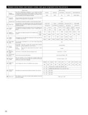
... ON On Screen Display ON Set the Trigger Out output for the dJffeterlt channels _rl order to obtain optimum effects Front L & R 12 ft (36 m) Front L OdB Front R 0dB Digitalh Assignment Video En Assign CD I DVD Th_s assigns the color difference {component) video input jacks fol the different input sources COAX1 DVD I COAX2 I I VDP VIDEO1 I NONE Turn the audio compresmo[_ on or off when dow[_ mixing Dolby Digital signals Power AMP Assignment Zone2 vol Level Default settings Sub Woofer Surround Sp Yes...
... ON On Screen Display ON Set the Trigger Out output for the dJffeterlt channels _rl order to obtain optimum effects Front L & R 12 ft (36 m) Front L OdB Front R 0dB Digitalh Assignment Video En Assign CD I DVD Th_s assigns the color difference {component) video input jacks fol the different input sources COAX1 DVD I COAX2 I I VDP VIDEO1 I NONE Turn the audio compresmo[_ on or off when dow[_ mixing Dolby Digital signals Power AMP Assignment Zone2 vol Level Default settings Sub Woofer Surround Sp Yes...


