
Operating Instructions
Page 9
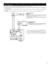
For details, see "Setting the video In Assignment" on page 24. • The AVR+2803's on some TVs, monitors or video components ("CR, CB and Y', "R- For details, carefully read the operating instructions included with the TV or other components. •... the COMPONENT MONETOR OUT jack using 75 OJohms coaxiaE video pimplug cords¸ • The color difference input jacks may be changed at the system setup. • When making connections, also refer to the operating instructions of the other component. 9 VIDEO OUT DVD player +++++I+ Connecting a DVD player ] r++l++ ,DVD IN jacks...
For details, see "Setting the video In Assignment" on page 24. • The AVR+2803's on some TVs, monitors or video components ("CR, CB and Y', "R- For details, carefully read the operating instructions included with the TV or other components. •... the COMPONENT MONETOR OUT jack using 75 OJohms coaxiaE video pimplug cords¸ • The color difference input jacks may be changed at the system setup. • When making connections, also refer to the operating instructions of the other component. 9 VIDEO OUT DVD player +++++I+ Connecting a DVD player ] r++l++ ,DVD IN jacks...
Operating Instructions
Page 16
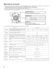
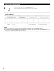
These settings are required to set up the listening room's AV system centered around the AVR-2803/983. • Check that the controls on the remote Auto Surround Mode = ON On Screen Display ON Set the Trigger Out output for the different ... Large Crossover Ftequency Set the frequency (Hz) below on the monitor screen using the AVR-2803/983'S on the screen. | ENTER button Press this to display the system setup menu. I A so use th s button to compete the setting. • System setup items and default values {set upon shipment from the factory) Speaker Configuration System...
These settings are required to set up the listening room's AV system centered around the AVR-2803/983. • Check that the controls on the remote Auto Surround Mode = ON On Screen Display ON Set the Trigger Out output for the different ... Large Crossover Ftequency Set the frequency (Hz) below on the monitor screen using the AVR-2803/983'S on the screen. | ENTER button Press this to display the system setup menu. I A so use th s button to compete the setting. • System setup items and default values {set upon shipment from the factory) Speaker Configuration System...
Operating Instructions
Page 17
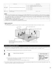
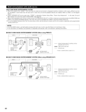
...playback devices connected to the S-Video monitor output. The settings that have been changed up , connect the AVR-2803/983's MONITOR OUT connector with small screens or low resolutions. • The setup menu is not displayed when headphones are being used. • Speaker system layout Basic system layout •...output with priority to the S-VIDEO MONITOR OUT jack during playback of all the connections are input to the AVR-2803/983 from the System Setup Menu screen. D8 E1 -- System setup can reset it may be changed settings are stored and the on the main unit's power. A8 B1 ...
...playback devices connected to the S-Video monitor output. The settings that have been changed up , connect the AVR-2803/983's MONITOR OUT connector with small screens or low resolutions. • The setup menu is not displayed when headphones are being used. • Speaker system layout Basic system layout •...output with priority to the S-VIDEO MONITOR OUT jack during playback of all the connections are input to the AVR-2803/983 from the System Setup Menu screen. D8 E1 -- System setup can reset it may be changed settings are stored and the on the main unit's power. A8 B1 ...
Operating Instructions
Page 23
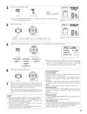
... activate the individual surround modes and adjust channel levels that mode will be remembered for each of the AVR-2803/983 for the different input sources. 1 At the System Setup Menu select "Digital In Assignment". 2 Switch to the Digital Inputs screen. After you have completed the... SYSTEM SETUP CHANNEL LEVEL adjustments, you adjust the channel levels while in the SYSTEM SETUP CHANNEL LEVEL mode, the channel level adjustments made will affect all surround modes. Consider this mode a...
... activate the individual surround modes and adjust channel levels that mode will be remembered for each of the AVR-2803/983 for the different input sources. 1 At the System Setup Menu select "Digital In Assignment". 2 Switch to the Digital Inputs screen. After you have completed the... SYSTEM SETUP CHANNEL LEVEL adjustments, you adjust the channel levels while in the SYSTEM SETUP CHANNEL LEVEL mode, the channel level adjustments made will affect all surround modes. Consider this mode a...
Operating Instructions
Page 24
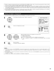
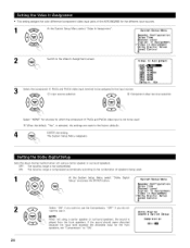
...which the component (Y, PB/C8 and P£/C£) video input is not to be used . 1 At the System Setup Menu select "Dolby Digital System Setup Menu Setup" and press the ENTER button. OFF: The dynamic range is not compressed. ON: The dynamic range is compressed automatically ... level exceeds the allowable input for the different input sources. 1 At the System Setup Menu select "Video In Assignment". • This setting assigns the color difference (component} video input jacks of the AVR-2803/983 for the front speakers, set "Compression" to the combination of speakers being...
...which the component (Y, PB/C8 and P£/C£) video input is not to be used . 1 At the System Setup Menu select "Dolby Digital System Setup Menu Setup" and press the ENTER button. OFF: The dynamic range is not compressed. ON: The dynamic range is compressed automatically ... level exceeds the allowable input for the different input sources. 1 At the System Setup Menu select "Video In Assignment". • This setting assigns the color difference (component} video input jacks of the AVR-2803/983 for the front speakers, set "Compression" to the combination of speakers being...
Operating Instructions
Page 30
... be pressed at any time during the system setup process to complete the process. _ s_ue_ At the System Setup Menu, press the SYSTEM SETUP button. ,_ The changed settings are entered and the on-screen display turns off. • On-screen display signals Signals input to the AVR-2803 VIDEO signal input iack (yellow) I x 2 o 3 x 4 O (o: Signal x: No...
... be pressed at any time during the system setup process to complete the process. _ s_ue_ At the System Setup Menu, press the SYSTEM SETUP button. ,_ The changed settings are entered and the on-screen display turns off. • On-screen display signals Signals input to the AVR-2803 VIDEO signal input iack (yellow) I x 2 o 3 x 4 O (o: Signal x: No...
Operating Instructions
Page 48
... ZONE. (See page 25.) • When a sold separately room to-room remote control unit (DENON RC-616, 6t7 or 618) is wired and connected between the MAIN ZONE and ZONE 2, the...controlled from ZONE 2 using SPEAKER OUT) MAIN ZONE PRREOMGORTEAMMABLE CONTROL UNIT ,N' I_ RG_16 m AVR-2803 _f SYSTEM REMOTE CONTROL UNIT RC 924 ...... SPEAKER cable Refer to CONNECTIONS on installation and ...this case, Surround Back Speaker Out cannot be used when "ZONE2" is selected at System Setup Menu "Power Amp Assignment". ROOM_O ROOM REMOTE CONTROL SYSTEM (separately sold) control line ZONE2 SPEAKER...
... ZONE. (See page 25.) • When a sold separately room to-room remote control unit (DENON RC-616, 6t7 or 618) is wired and connected between the MAIN ZONE and ZONE 2, the...controlled from ZONE 2 using SPEAKER OUT) MAIN ZONE PRREOMGORTEAMMABLE CONTROL UNIT ,N' I_ RG_16 m AVR-2803 _f SYSTEM REMOTE CONTROL UNIT RC 924 ...... SPEAKER cable Refer to CONNECTIONS on installation and ...this case, Surround Back Speaker Out cannot be used when "ZONE2" is selected at System Setup Menu "Power Amp Assignment". ROOM_O ROOM REMOTE CONTROL SYSTEM (separately sold) control line ZONE2 SPEAKER...
Operating Instructions
Page 51
AFDM 4_ TSOBNECH t OUT 4NRML (OF F) ) [_ Yes_ TIlls is performed from the main unit or the remote control unit. Set the surround parameter mode. 8URROLIND p,_%_IEIER 8um_o "DOLBY PL I I C I NEMA EQ. (Main unit) _u_'_ (Remote control unit) IDiOispDlayE c i The on-screen display differs according to whether the operation is the screen when operated with tile remote control unit 4 Select the play mode. SELECT "DOLBY PL II OPTIONS4 (Main unit) DispEay i,i0[::,E,::i (Remote control unit) i,i0[::,EDOLi..:iPML AFDM
AFDM 4_ TSOBNECH t OUT 4NRML (OF F) ) [_ Yes_ TIlls is performed from the main unit or the remote control unit. Set the surround parameter mode. 8URROLIND p,_%_IEIER 8um_o "DOLBY PL I I C I NEMA EQ. (Main unit) _u_'_ (Remote control unit) IDiOispDlayE c i The on-screen display differs according to whether the operation is the screen when operated with tile remote control unit 4 Select the play mode. SELECT "DOLBY PL II OPTIONS4 (Main unit) DispEay i,i0[::,E,::i (Remote control unit) i,i0[::,EDOLi..:iPML AFDM
Operating Instructions
Page 64
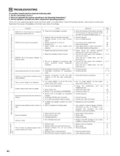
... power back on • Connect securely • Connect securely • Check left and right connections • Set "on screen display" on the system setup menu screen to on * Check the insertion of the power cord plug • Turn the power on • Unplug the headphones headphones iack • ... set to off on the system setup menu screen • You are using headphones • Mute mode is set 's powel, then ventilate it well to the Operating instructions ? 3. o_ E oE o The on • Turn off the set • Monitor TV not connected to AVR-2803/983 • Ground wire of ...
... power back on • Connect securely • Connect securely • Check left and right connections • Set "on screen display" on the system setup menu screen to on * Check the insertion of the power cord plug • Turn the power on • Unplug the headphones headphones iack • ... set to off on the system setup menu screen • You are using headphones • Mute mode is set 's powel, then ventilate it well to the Operating instructions ? 3. o_ E oE o The on • Turn off the set • Monitor TV not connected to AVR-2803/983 • Ground wire of ...


