
Operating Instructions
Page 9
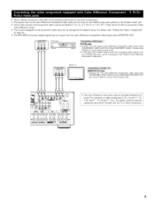
... operating instructions included with component video Outputs such as a TV/DBS tuner, etc, can be changed at the system setup. For details, see "Setting the video In Assignment" on page 24. • The AVR+2803's on some TVs, monitors or video components ("CR, CB and Y', "R- • When making connections, also refer to the...
... operating instructions included with component video Outputs such as a TV/DBS tuner, etc, can be changed at the system setup. For details, see "Setting the video In Assignment" on page 24. • The AVR+2803's on some TVs, monitors or video components ("CR, CB and Y', "R- • When making connections, also refer to the...
Operating Instructions
Page 16
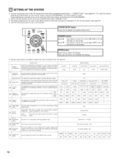
...completed as described in "CONNECTIONS" (see page 63). • Use the following buttons to set up the listening room's AV system centered around the AVR-2803/983. • Check that the controls on the remote Auto Surround Mode = ON On Screen Display ON Set the Trigger Out output for playing deep... bass signals Delay %me This parameter is set up the system: _s SETU P button t to display the system setup menu. [] SETTING UP THE SYSTEM • Once all connections with which the bass sound of the vanous speakers is to be reset to the default...
...completed as described in "CONNECTIONS" (see page 63). • Use the following buttons to set up the listening room's AV system centered around the AVR-2803/983. • Check that the controls on the remote Auto Surround Mode = ON On Screen Display ON Set the Trigger Out output for playing deep... bass signals Delay %me This parameter is set up the system: _s SETU P button t to display the system setup menu. [] SETTING UP THE SYSTEM • Once all connections with which the bass sound of the vanous speakers is to be reset to the default...
Operating Instructions
Page 17
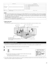
...memory Set whether or not to lock tile system setup settlrlgs so that all playback devices connected to the AVR-2803/983's video input connectors. (For instructions on connecting the monitor TV, see page 30.) • The AVR-2803/983'S on-screen display function is designed for ... To stop system setup before it by selecting the desired menu from a video source (VDP, etc.) connected to both the AVR-2803/983'S S-Video and video monitor output jacks and signals are input to the AVR-2803/983 from the System Setup Menu screen. @ APuretosetTsuner _ Setup Lock System setup FM stations are ...
...memory Set whether or not to lock tile system setup settlrlgs so that all playback devices connected to the AVR-2803/983's video input connectors. (For instructions on connecting the monitor TV, see page 30.) • The AVR-2803/983'S on-screen display function is designed for ... To stop system setup before it by selecting the desired menu from a video source (VDP, etc.) connected to both the AVR-2803/983'S S-Video and video monitor output jacks and signals are input to the AVR-2803/983 from the System Setup Menu screen. @ APuretosetTsuner _ Setup Lock System setup FM stations are ...
Operating Instructions
Page 23
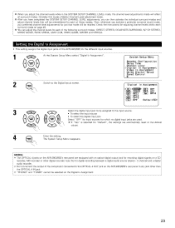
Check the instructions for adjusting channel levels within each surround mode on page 49. After you have completed the SYSTEM SETUP CHANNEL LEVEL adjustments, you can adjust the channel levels for each of the following surround modes: DIRECT, STEREO, DOLBY/DTS SURROUND, 5/7... adjust channel levels that mode will be remembered for each of the AVR-2803/983 for the different input sources. 1 At the System Setup Menu select "Digital In Assignment". 2 Switch to the Digital Inputs screen. System Setup Menu Speaker Configuration Delay Time Channel Level ErDigital In Assignment Video In ...
Check the instructions for adjusting channel levels within each surround mode on page 49. After you have completed the SYSTEM SETUP CHANNEL LEVEL adjustments, you can adjust the channel levels for each of the following surround modes: DIRECT, STEREO, DOLBY/DTS SURROUND, 5/7... adjust channel levels that mode will be remembered for each of the AVR-2803/983 for the different input sources. 1 At the System Setup Menu select "Digital In Assignment". 2 Switch to the Digital Inputs screen. System Setup Menu Speaker Configuration Delay Time Channel Level ErDigital In Assignment Video In ...
Operating Instructions
Page 24
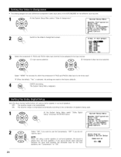
... the color difference (component} video input jacks of speakers being used . -_ When the default, "Yes", is not compressed. The System Setup Menu reappears. 4 ENTER the setting. Compression 24 ON: The dynamic range is NplOayTeEd: from the front speakers. OFF: The dynamic range ...a center speaker or surround speakers, the sound is compressed automatically according to the combination of the AVR-2803/983 for the different input sources. 1 At the System Setup Menu select "Video In Assignment". Speaker Configuration Delay Time Channel Level Digital In Assignment Video In ...
... the color difference (component} video input jacks of speakers being used . -_ When the default, "Yes", is not compressed. The System Setup Menu reappears. 4 ENTER the setting. Compression 24 ON: The dynamic range is NplOayTeEd: from the front speakers. OFF: The dynamic range ...a center speaker or surround speakers, the sound is compressed automatically according to the combination of the AVR-2803/983 for the different input sources. 1 At the System Setup Menu select "Video In Assignment". Speaker Configuration Delay Time Channel Level Digital In Assignment Video In ...
Operating Instructions
Page 30
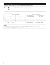
... be pressed at any time during the system setup process to complete the process. _ s_ue_ At the System Setup Menu, press the SYSTEM SETUP button. ,_ The changed settings are entered and the on-screen display turns off. • On-screen display signals Signals input to the AVR-2803 VIDEO signal input iack (yellow) I x 2 o 3 x 4 O (o: Signal x: No...
... be pressed at any time during the system setup process to complete the process. _ s_ue_ At the System Setup Menu, press the SYSTEM SETUP button. ,_ The changed settings are entered and the on-screen display turns off. • On-screen display signals Signals input to the AVR-2803 VIDEO signal input iack (yellow) I x 2 o 3 x 4 O (o: Signal x: No...
Operating Instructions
Page 48
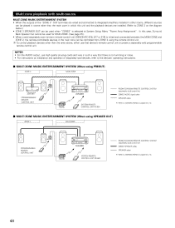
... ZONE. (See page 25.) • When a sold separately room to-room remote control unit (DENON RC-616, 6t7 or 618) is selected at System Setup Menu "Power Amp Assignment". MULTI ZONE MUSIC ENTERTAINMENT SYSTEM • When the outputs of separately sold ...devices, refer to the devices' operating instructions. • MULTI ZONE MUSIC ENTERTAINMENT ZONE 2 SYSTEM (When using PREOUT} MAIN ZONE _NTEGRATED AMPLIFIER PROGRAMMABLE REMOTE CONTROL UNiT ,_ ttN' I_ AVR-2803 ...
... ZONE. (See page 25.) • When a sold separately room to-room remote control unit (DENON RC-616, 6t7 or 618) is selected at System Setup Menu "Power Amp Assignment". MULTI ZONE MUSIC ENTERTAINMENT SYSTEM • When the outputs of separately sold ...devices, refer to the devices' operating instructions. • MULTI ZONE MUSIC ENTERTAINMENT ZONE 2 SYSTEM (When using PREOUT} MAIN ZONE _NTEGRATED AMPLIFIER PROGRAMMABLE REMOTE CONTROL UNiT ,_ ttN' I_ AVR-2803 ...
Operating Instructions
Page 51
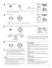
Set the surround parameter mode. 8URROLIND p,_%_IEIER 8um_o "DOLBY PL I I C I NEMA EQ. (Main unit) _u_'_ (Remote control unit) IDiOispDlayE c i The on-screen display differs according to whether the operation is the screen when operated with tile remote control unit 4 Select the play mode. AFDM 4_ TSOBNECH t OUT 4NRML (OF F) ) [_ Yes_ TIlls is performed from the main unit or the remote control unit. SELECT "DOLBY PL II OPTIONS4 (Main unit) DispEay i,i0[::,E,::i (Remote control unit) i,i0[::,EDOLi..:iPML AFDM
Set the surround parameter mode. 8URROLIND p,_%_IEIER 8um_o "DOLBY PL I I C I NEMA EQ. (Main unit) _u_'_ (Remote control unit) IDiOispDlayE c i The on-screen display differs according to whether the operation is the screen when operated with tile remote control unit 4 Select the play mode. AFDM 4_ TSOBNECH t OUT 4NRML (OF F) ) [_ Yes_ TIlls is performed from the main unit or the remote control unit. SELECT "DOLBY PL II OPTIONS4 (Main unit) DispEay i,i0[::,E,::i (Remote control unit) i,i0[::,EDOLi..:iPML AFDM
Operating Instructions
Page 64
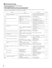
...back on • Connect securely • Connect securely • Check left and right connections • Set "on screen display" on the system setup menu screen to on _" 8 o DISPLAY lit but sound not produced 8 DISPLAY not lit and power indicator is cooled down, turn the power ...8226; Connect securely • Contact your store of battery inser[ed in securely d when power switch set • Monitor TV not connected to AVR-2803/983 • Ground wire of turntable not connected properly • Incomplete PHONO jack connection • TV or radio transmission antenna nearby •...
...back on • Connect securely • Connect securely • Check left and right connections • Set "on screen display" on the system setup menu screen to on _" 8 o DISPLAY lit but sound not produced 8 DISPLAY not lit and power indicator is cooled down, turn the power ...8226; Connect securely • Contact your store of battery inser[ed in securely d when power switch set • Monitor TV not connected to AVR-2803/983 • Ground wire of turntable not connected properly • Incomplete PHONO jack connection • TV or radio transmission antenna nearby •...


