

Owners Manual
Page 2
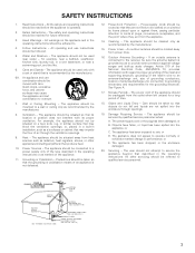
... LE NUMERO DE SERIE DE L'APPAREIL INSCRIT A L'ARRIERE DU COFFRET DE FAÇON A POUVOIR LE CONSULTER EN CAS DE PROBLEME." 2 NOTE ON USE / OBSERVATIONS RELATIVES A L'UTILISATION • Avoid high temperatures. This Class B digital apparatus meets all requirements of the FCC Rules. "SERIAL NO. The ..., and dust. • Protéger l'appareil contre l'humidité, l'eau et lapoussière. • Unplug the power cord when not using the set for long periods of time. • Débrancher le cordon d'alimentation lorsque l'appareil n'est pas utilisé pendant de longues pé...
... LE NUMERO DE SERIE DE L'APPAREIL INSCRIT A L'ARRIERE DU COFFRET DE FAÇON A POUVOIR LE CONSULTER EN CAS DE PROBLEME." 2 NOTE ON USE / OBSERVATIONS RELATIVES A L'UTILISATION • Avoid high temperatures. This Class B digital apparatus meets all requirements of the FCC Rules. "SERIAL NO. The ..., and dust. • Protéger l'appareil contre l'humidité, l'eau et lapoussière. • Unplug the power cord when not using the set for long periods of time. • Débrancher le cordon d'alimentation lorsque l'appareil n'est pas utilisé pendant de longues pé...
Owners Manual
Page 3
...grounding of the lead-in installation, such as recommended by the manufacturer. 6A. Follow Instructions - Water and Moisture - The appliance should be used near water - The appliance should be mounted to a wall or ceiling only as a bookcase or cabinet that may impede the flow of...produce heat. 10. Objects have fallen, or liquid has been spilled into the enclosure through the ventilation openings. 9. Servicing - All operating and use instructions should be unplugged from power lines. 16. Heat - Power Lines - Object and Liquid Entry - or D. NATIONAL ELECTRICAL CODE ANTENNA ...
...grounding of the lead-in installation, such as recommended by the manufacturer. 6A. Follow Instructions - Water and Moisture - The appliance should be used near water - The appliance should be mounted to a wall or ceiling only as a bookcase or cabinet that may impede the flow of...produce heat. 10. Objects have fallen, or liquid has been spilled into the enclosure through the ventilation openings. 9. Servicing - All operating and use instructions should be unplugged from power lines. 16. Heat - Power Lines - Object and Liquid Entry - or D. NATIONAL ELECTRICAL CODE ANTENNA ...

Owners Manual
Page 4
... Memory 47 ⁄4 Initialization of features, we recommend that before connecting and disconnecting connection cords. • Store this unit or any other electronic equipment using microprocessors is used near a tuner or TV. Always set . • Before turning the power switch on Handling 5 v Features 5 b Connections 6~11 n Part Names and Functions ... tuner or TV. • Set the antenna wires from the tuner or TV away from the actual set for choosing the DENON AVR-2801/981 Digital Surround A / V receiver. We recommend using indoor antennas or 300 Ω/ohms feeder wires.
... Memory 47 ⁄4 Initialization of features, we recommend that before connecting and disconnecting connection cords. • Store this unit or any other electronic equipment using microprocessors is used near a tuner or TV. Always set . • Before turning the power switch on Handling 5 v Features 5 b Connections 6~11 n Part Names and Functions ... tuner or TV. • Set the antenna wires from the tuner or TV away from the actual set for choosing the DENON AVR-2801/981 Digital Surround A / V receiver. We recommend using indoor antennas or 300 Ω/ohms feeder wires.

Owners Manual
Page 5
DTS (Digital Theater Systems) DTS provides up to 5.1 channels of wide-range, high fidelity surround sound. If the volume is changed. Dolby Digital Using advanced digital processing algorithms, Dolby Digital provides up during this time, the output will be very high after the muting circuit stops functioning. If this , ...
DTS (Digital Theater Systems) DTS provides up to 5.1 channels of wide-range, high fidelity surround sound. If the volume is changed. Dolby Digital Using advanced digital processing algorithms, Dolby Digital provides up during this time, the output will be very high after the muting circuit stops functioning. If this , ...

Owners Manual
Page 6
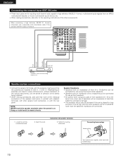
...Refer to this unit's tape playback (CDR/TAPE IN) jacks using pin plug cords. AC 120V 60HZ AC OUTLETS Turntable (MM cartridge) Ground wire ANTENNA EXT. Connecting a turntable Connect the turntable's output cord to the AVR-2801/981's PHONO jacks, the L (left , right with ...digital output. NOTES: • Use 75 Ω/ohms cable pin cords for coaxial connections. • Use optical cables for optical connections, removing the cap before connecting. 6...
...Refer to this unit's tape playback (CDR/TAPE IN) jacks using pin plug cords. AC 120V 60HZ AC OUTLETS Turntable (MM cartridge) Ground wire ANTENNA EXT. Connecting a turntable Connect the turntable's output cord to the AVR-2801/981's PHONO jacks, the L (left , right with ...digital output. NOTES: • Use 75 Ω/ohms cable pin cords for coaxial connections. • Use optical cables for optical connections, removing the cap before connecting. 6...

Owners Manual
Page 7
... 9kHz 10kHz FR LOOP ANT. MONITOR OUT • Connect the TV's video input jack (VIDEO INPUT) to the VIDEO (yellow) VCR-1 OUT jack using pin plug cords. • A DVD player can result in a drop in video quality. • When making connections, also refer to the operating instructions... input jacks • Only audio signals are two sets of the other components. ENGLISH Connecting video components • To connect the video signal, connect using a 75 Ω/ohms video coaxial pin plug cord. • Connect the TV's or DBS tuner's audio output jacks (AUDIO OUTPUT) to the...
... 9kHz 10kHz FR LOOP ANT. MONITOR OUT • Connect the TV's video input jack (VIDEO INPUT) to the VIDEO (yellow) VCR-1 OUT jack using pin plug cords. • A DVD player can result in a drop in video quality. • When making connections, also refer to the operating instructions... input jacks • Only audio signals are two sets of the other components. ENGLISH Connecting video components • To connect the video signal, connect using a 75 Ω/ohms video coaxial pin plug cord. • Connect the TV's or DBS tuner's audio output jacks (AUDIO OUTPUT) to the...

Owners Manual
Page 8
... video component equipped with S-Video jacks • When making connections, also refer to the operating instructions of the other . • Precaution when using S-jacks This unit's S-jacks (input and output) and video pin jacks (input and output) have independent circuit structures, so that is also possible...VDP) S-VIDEO OUT Connecting a monitor TV MONITOR OUT • Connect the TV's S video input (S-VIDEO INPUT) to the S-VIDEO TV/DBS IN jack using a S jack connection cord. S-VIDEO OUT Monitor TV S-VIDEO IN Connecting a TV/DBS tuner • Connect the TV's or DBS tuner's S video ...
... video component equipped with S-Video jacks • When making connections, also refer to the operating instructions of the other . • Precaution when using S-jacks This unit's S-jacks (input and output) and video pin jacks (input and output) have independent circuit structures, so that is also possible...VDP) S-VIDEO OUT Connecting a monitor TV MONITOR OUT • Connect the TV's S video input (S-VIDEO INPUT) to the S-VIDEO TV/DBS IN jack using a S jack connection cord. S-VIDEO OUT Monitor TV S-VIDEO IN Connecting a TV/DBS tuner • Connect the TV's or DBS tuner's S video ...

Owners Manual
Page 9
... external AM antenna is provided to call the CATV system installer's attention to the point of the F-type, connect using the included antenna adapter. Note to CATV system installer: This reminder is used, do not disconnect the AM loop antenna. • Make sure AM loop antenna lead terminals do not touch metal...
... external AM antenna is provided to call the CATV system installer's attention to the point of the F-type, connect using the included antenna adapter. Note to CATV system installer: This reminder is used, do not disconnect the AM loop antenna. • Make sure AM loop antenna lead terminals do not touch metal...
Owners Manual
Page 10
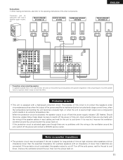
... when the power is monaural. Loosen by turning clockwise. Mismatching of polarities will lead to damage. • The protector circuit may be connected for use as surround and center speakers. • Speakers with an impedance of 6 to 16 Ω/ohms can be connected for... Connecting the external input (EXT. IN) jacks • These input jacks are for long periods of time at the same time, since use as front speakers. • Be careful when using two pairs of front speakers (A + B) at high volumes when speakers with other components. R ANTENNA 9kHz EXT. SW C VDP AM R SR ...
... when the power is monaural. Loosen by turning clockwise. Mismatching of polarities will lead to damage. • The protector circuit may be connected for use as surround and center speakers. • Speakers with an impedance of 6 to 16 Ω/ohms can be connected for... Connecting the external input (EXT. IN) jacks • These input jacks are for long periods of time at the same time, since use as front speakers. • Be careful when using two pairs of front speakers (A + B) at high volumes when speakers with other components. R ANTENNA 9kHz EXT. SW C VDP AM R SR ...
Owners Manual
Page 11
... circuit. If the protection circuit is very hot. Protector circuit • This unit is cut off the power and contact a DENON service center. If the protector circuit is activated, the speaker output is equipped with the wiring or the ventilation around the set... CENTER L L R R SUB SURROUND WOOFER FRONT PRE OUT CENTER FRONT RBL FRONT RAL SPEAKER SYSTEMS • Precautions when connecting speakers If a speaker is used at high volumes when speakers with an impedance lower than 4 Ω/ohms) are connected. Turn off . The purpose of the other components. IN R...
... circuit. If the protection circuit is very hot. Protector circuit • This unit is cut off the power and contact a DENON service center. If the protector circuit is activated, the speaker output is equipped with the wiring or the ventilation around the set... CENTER L L R R SUB SURROUND WOOFER FRONT PRE OUT CENTER FRONT RBL FRONT RAL SPEAKER SYSTEMS • Precautions when connecting speakers If a speaker is used at high volumes when speakers with an impedance lower than 4 Ω/ohms) are connected. Turn off . The purpose of the other components. IN R...

Owners Manual
Page 13
...buttons 24) SPEAKER select button 31) Surround buttons 24) INPUT MODE selector buttons 32) Mode selector switches 27) Tuner system buttons 24) USE/LEARN selector button 28) Test tone button 36) SYSTEM SETUP button 14) Master volume control buttons 33) MUTING button 34) SURROUND PARAMETER ...SETUP button 27) STATUS button 34) NOTE • The shaded buttons do not function with the AVR-2801/981. (Nothing happens when they are pressed.) The button indicated , however, can be used with the learning function. 13 Remote control unit • For details on the functions of these...
...buttons 24) SPEAKER select button 31) Surround buttons 24) INPUT MODE selector buttons 32) Mode selector switches 27) Tuner system buttons 24) USE/LEARN selector button 28) Test tone button 36) SYSTEM SETUP button 14) Master volume control buttons 33) MUTING button 34) SURROUND PARAMETER ...SETUP button 27) STATUS button 34) NOTE • The shaded buttons do not function with the AVR-2801/981. (Nothing happens when they are pressed.) The button indicated , however, can be used with the learning function. 13 Remote control unit • For details on the functions of these...
Owners Manual
Page 14
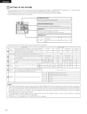
...90.1/90.1 MHz y Auto Tuner Presets FM stations are required to set up the listening room's AV system centered around the AVR-2801/981. • Use the following buttons to switch the display on the screen. • System setup items and default values (set the composition of... 0 dB Center 0 dB Surround L Surround R 0 dB 0 dB This assigns the digital input jacks for use this to 11), make the various settings described below on the monitor screen using the AVR-2801/981's on the screen. Large Default settings Center Sp. Surround Sp. AUX OFF This sets whether or not...
...90.1/90.1 MHz y Auto Tuner Presets FM stations are required to set up the listening room's AV system centered around the AVR-2801/981. • Use the following buttons to switch the display on the screen. • System setup items and default values (set the composition of... 0 dB Center 0 dB Surround L Surround R 0 dB 0 dB This assigns the digital input jacks for use this to 11), make the various settings described below on the monitor screen using the AVR-2801/981's on the screen. Large Default settings Center Sp. Surround Sp. AUX OFF This sets whether or not...
Owners Manual
Page 15
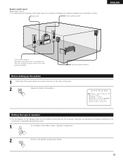
... speaker systems Set these at the sides of the TV or screen with their front surfaces as flush with the front of speakers actually being used. 1 At the System Setup Menu select "Speaker Configuration". 2 ENTER Switch to the combination of the screen as possible. Setting the type of speakers • The...
... speaker systems Set these at the sides of the TV or screen with their front surfaces as flush with the front of speakers actually being used. 1 At the System Setup Menu select "Speaker Configuration". 2 ENTER Switch to the combination of the screen as possible. Setting the type of speakers • The...
Owners Manual
Page 16
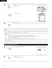
Select this when using speakers that can be achieved even when "Small" is selected, low frequencies of below 80 Hz with ...(setting the volume to a level low enough so as not to damage the speakers) to the subwoofer. Select this when using the SMALL setting for all five main speakers and Subwooofer On with sufficient volume. None...... Subwoofer Surround Sp. Small...... Select this... to the speaker's capacity for the front, center and surround speakers. * For the majority of speaker system configurations, using speakers that cannot reproduce low sounds of below ) signals.
Select this when using speakers that can be achieved even when "Small" is selected, low frequencies of below 80 Hz with ...(setting the volume to a level low enough so as not to damage the speakers) to the subwoofer. Select this when using the SMALL setting for all five main speakers and Subwooofer On with sufficient volume. None...... Subwoofer Surround Sp. Small...... Select this... to the speaker's capacity for the front, center and surround speakers. * For the majority of speaker system configurations, using speakers that cannot reproduce low sounds of below ) signals.
Owners Manual
Page 19
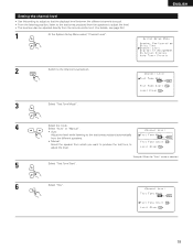
... be adjusted directly from which you want to produce the test tone to adjust the level. 5 Select "Test Tone Start". Setting the channel level • Use this setting to adjust so that the playback level between the different channels is selected 6 Select "Yes". 19
... be adjusted directly from which you want to produce the test tone to adjust the level. 5 Select "Test Tone Start". Setting the channel level • Use this setting to adjust so that the playback level between the different channels is selected 6 Select "Yes". 19

Owners Manual
Page 20
... intervals the first time and second time around, 2second intervals the third time around and on: 1 FL 1C 1 FR 1 SR 1 SL 1 SW Use the CURSOR buttons to adjust all the speakers to adjust the subwoofer's own volume control. * When you activate a particular surround sound mode, your preferred channel...is selected: Test tones are completed, press the ENTER button. Then, whenever you adjust the channel levels while in units of each of the AVR-2801/981 for just that the volume from the different speakers sounds the same. 8 ENTER Example: When the volume is set to -12 dB while...
... intervals the first time and second time around, 2second intervals the third time around and on: 1 FL 1C 1 FR 1 SR 1 SL 1 SW Use the CURSOR buttons to adjust all the speakers to adjust the subwoofer's own volume control. * When you activate a particular surround sound mode, your preferred channel...is selected: Test tones are completed, press the ENTER button. Then, whenever you adjust the channel levels while in units of each of the AVR-2801/981 for just that the volume from the different speakers sounds the same. 8 ENTER Example: When the volume is set to -12 dB while...

Owners Manual
Page 21
.... • To select the input source • To select the digital input jack Select "OFF" for input sources for which no digital input jacks are used. * If "Yes" is selected for "Default", the settings are automatically reset to the Digital In Assignment screen. 2 ENTER Switch to the default values. The System... Setup Menu reappears. 21 The System Setup Menu reappears. Setting the on-screen display (OSD) • Use this to turn the on-screen display (messages other than the menu screens) on the Digital Inputs screen.
.... • To select the input source • To select the digital input jack Select "OFF" for input sources for which no digital input jacks are used. * If "Yes" is selected for "Default", the settings are automatically reset to the Digital In Assignment screen. 2 ENTER Switch to the default values. The System... Setup Menu reappears. 21 The System Setup Menu reappears. Setting the on-screen display (OSD) • Use this to turn the on-screen display (messages other than the menu screens) on the Digital Inputs screen.

Owners Manual
Page 22
...to specify "Auto Tuner Presets" from the "System Setup Menu" screen. 2 ENTER Press the ENTER button. ENGLISH Auto tuner presets Use this to automatically search for FM broadcasts and store up to 40 stations at any time during the system setup process to complete ... the SYSTEM SETUP button. * The changed settings are entered and the on-screen display turns off. • On-screen display signals Signals input to the AVR-2801/981 VIDEO signal input jack (yellow) S-video signal input jack 1 E E 2 C E 3 E C 4 C C (C: Signal E: No signal) On-screen display signal output VIDEO ...
...to specify "Auto Tuner Presets" from the "System Setup Menu" screen. 2 ENTER Press the ENTER button. ENGLISH Auto tuner presets Use this to automatically search for FM broadcasts and store up to 40 stations at any time during the system setup process to complete ... the SYSTEM SETUP button. * The changed settings are entered and the on-screen display turns off. • On-screen display signals Signals input to the AVR-2801/981 VIDEO signal input jack (yellow) S-video signal input jack 1 E E 2 C E 3 E C 4 C C (C: Signal E: No signal) On-screen display signal output VIDEO ...

Owners Manual
Page 23
NOTES: • It may be used to operate not only the AVR-2801/981 but this depends on . The factory-installed codes are in malfunction, so keep the set . • When inserting the batteries, be sure to do not plan to use a new battery together with a function for an extended ...simultaneously. Furthermore, it for learning the control signals of remote control units of up to 30 degrees with respect to operate non-DENON remote control compatible video components. Using the remote control unit Approx. 7 m/22 feet 30° 30° • Point the remote control unit at ...
NOTES: • It may be used to operate not only the AVR-2801/981 but this depends on . The factory-installed codes are in malfunction, so keep the set . • When inserting the batteries, be sure to do not plan to use a new battery together with a function for an extended ...simultaneously. Furthermore, it for learning the control signals of remote control units of up to 30 degrees with respect to operate non-DENON remote control compatible video components. Using the remote control unit Approx. 7 m/22 feet 30° 30° • Point the remote control unit at ...

Owners Manual
Page 24
... tuner only, the following buttons can also be operated. ENGLISH Operating DENON audio components • Turn on the power of components may not be operated with this remote control. 1. AUDIO DECK CDR/MD CD MUTING AVR/AVC VIDEO TUNING DVD TV VDP VCR SYSTEM SETUP SURROUND PARAMETER BAND... MODE MEMORY TITLE MENU/GUIDE CH SELECT ENTER SELECT STATUS ON SCREEN DISPLAY RETURN USE/LEARN T.TONE DVD SET UP 3 2 3 Operate the audio component...
... tuner only, the following buttons can also be operated. ENGLISH Operating DENON audio components • Turn on the power of components may not be operated with this remote control. 1. AUDIO DECK CDR/MD CD MUTING AVR/AVC VIDEO TUNING DVD TV VDP VCR SYSTEM SETUP SURROUND PARAMETER BAND... MODE MEMORY TITLE MENU/GUIDE CH SELECT ENTER SELECT STATUS ON SCREEN DISPLAY RETURN USE/LEARN T.TONE DVD SET UP 3 2 3 Operate the audio component...


