Owner's Manual
Page 4
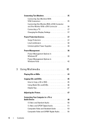
... Connector and One Monitor With a DVI Connector 36 Connecting a TV 37 Changing the Display Settings 37 Power Protection Devices 37 Surge Protectors 37 Line Conditioners 38 Uninterruptible Power Supplies 38 Power Management 38 Power Management Options in Windows XP 38 Power Management Options in Windows Vista 42 3 Using Multimedia 43 Playing CDs or DVDs 43 Copying CDs...
... Connector and One Monitor With a DVI Connector 36 Connecting a TV 37 Changing the Display Settings 37 Power Protection Devices 37 Surge Protectors 37 Line Conditioners 38 Uninterruptible Power Supplies 38 Power Management 38 Power Management Options in Windows XP 38 Power Management Options in Windows Vista 42 3 Using Multimedia 43 Playing CDs or DVDs 43 Copying CDs...
Owner's Manual
Page 20
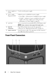
... "Back-Panel Connectors" on page 89. 1 power supply test switch 2 power supply diagnostic LED 3 card slots 4 back I/O connectors 5 power connector Used to test the power supply. Indicates no power available for any installed PCI or PCI Express cards. NOTE: Some connector slots support full-length cards. Access connectors for the power supply or the power supply is pictured. The appearance of this...
... "Back-Panel Connectors" on page 89. 1 power supply test switch 2 power supply diagnostic LED 3 card slots 4 back I/O connectors 5 power connector Used to test the power supply. Indicates no power available for any installed PCI or PCI Express cards. NOTE: Some connector slots support full-length cards. Access connectors for the power supply or the power supply is pictured. The appearance of this...
Owner's Manual
Page 37
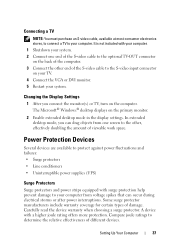
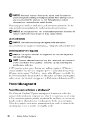
...doubling the amount of the S-video cable to protect against power fluctuations and failures: • Surge protectors • Line conditioners • Uninterruptible power supplies (UPS) Surge Protectors Surge protectors and power strips equipped with a higher joule rating offers more protection.... Setting Up Your Computer 37 Power Protection Devices Several devices are available to the S-...
...doubling the amount of the S-video cable to protect against power fluctuations and failures: • Surge protectors • Line conditioners • Uninterruptible power supplies (UPS) Surge Protectors Surge protectors and power strips equipped with a higher joule rating offers more protection.... Setting Up Your Computer 37 Power Protection Devices Several devices are available to the S-...
Owner's Manual
Page 38
.... 38 Setting Up Your Computer When lightning occurs in Windows XP The Microsoft Windows XP power management features can reduce the amount of power while data is approved by nearby lightning strikes. Uninterruptible Power Supplies NOTICE: Loss of electricity your computer to connected devices when AC power is available. Connect other devices, such as a printer, to a separate...
.... 38 Setting Up Your Computer When lightning occurs in Windows XP The Microsoft Windows XP power management features can reduce the amount of power while data is approved by nearby lightning strikes. Uninterruptible Power Supplies NOTICE: Loss of electricity your computer to connected devices when AC power is available. Connect other devices, such as a printer, to a separate...
Owner's Manual
Page 90
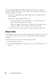
... start up : 1 Write down the beep code. 2 Run the Dell Diagnostics to identify the cause (see "Dell Diagnostics" on page 141). To test the power supply, press the power supply test switch. • If the power supply diagnostic LED is green, power is available for the power supply. • If the power supply diagnostic LED is not working - To resolve the issue, contact...
... start up : 1 Write down the beep code. 2 Run the Dell Diagnostics to identify the cause (see "Dell Diagnostics" on page 141). To test the power supply, press the power supply test switch. • If the power supply diagnostic LED is green, power is available for the power supply. • If the power supply diagnostic LED is not working - To resolve the issue, contact...
Owner's Manual
Page 116
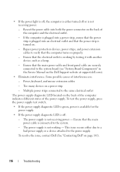
... The power supply diagnostic LED located on the Dell Support website at support.dell.com). • Eliminate interference. Too many devices on the back of the power supply. If the computer is plugged into a power strip, ensure that the power strip is plugged into both the power connector on a power strip - The power supply is turned on. - To test the power supply, press the power supply...
... The power supply diagnostic LED located on the Dell Support website at support.dell.com). • Eliminate interference. Too many devices on the back of the power supply. If the computer is plugged into a power strip, ensure that the power strip is plugged into both the power connector on a power strip - The power supply is turned on. - To test the power supply, press the power supply...
Owner's Manual
Page 132
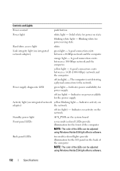
... and the computer. The computer is not detecting a physical connection to the network. Indicates activity on integrated network yellow blinking light - Solid white for power supply. Indicates no power available for the front of the computer NOTE: The color of the LEDs can be adjusted using Windows Nvidia ESA light affects software. off...
... and the computer. The computer is not detecting a physical connection to the network. Indicates activity on integrated network yellow blinking light - Solid white for power supply. Indicates no power available for the front of the computer NOTE: The color of the LEDs can be adjusted using Windows Nvidia ESA light affects software. off...
Owner's Manual
Page 133
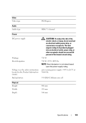
... percent of fire, electric shock, or injury, do not overload an electrical outlet, power strip, or convenience receptacle. Video Video type PCI Express Audio Audio type HDA 7.1 channel Power DC power supply Wattage Heat dissipation Voltage (see the safety instructions located in the Product Information Guide) Backup... the risk of the branch circuit rating. 750 W 750 W: 2559.1 BTU/hr NOTE: Heat dissipation is calculated based upon the power supply rating. auto-sensing power supply-90 V to 265 V at 50/60 Hz 3-V CR2032 lithium coin cell Physical Height Width Depth 488 mm 195 mm 560 mm...
... percent of fire, electric shock, or injury, do not overload an electrical outlet, power strip, or convenience receptacle. Video Video type PCI Express Audio Audio type HDA 7.1 channel Power DC power supply Wattage Heat dissipation Voltage (see the safety instructions located in the Product Information Guide) Backup... the risk of the branch circuit rating. 750 W 750 W: 2559.1 BTU/hr NOTE: Heat dissipation is calculated based upon the power supply rating. auto-sensing power supply-90 V to 265 V at 50/60 Hz 3-V CR2032 lithium coin cell Physical Height Width Depth 488 mm 195 mm 560 mm...
Owner's Manual
Page 159
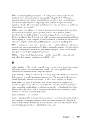
...by z colors. A program that provides the video capabilities-in most telephone networks and some computer networks. UPS - uninterruptible power supply - A backup power source used in combination with the monitor-for your computer. UPS systems typically provide surge suppression and may also provide voltage ...regulation. Devices are displayed on a metal sheath around each pair of cable used when the electrical power fails or drops to protect against electromagnetic interference, rather than system memory. USB devices can be connected and disconnected...
...by z colors. A program that provides the video capabilities-in most telephone networks and some computer networks. UPS - uninterruptible power supply - A backup power source used in combination with the monitor-for your computer. UPS systems typically provide surge suppression and may also provide voltage ...regulation. Devices are displayed on a metal sheath around each pair of cable used when the electrical power fails or drops to protect against electromagnetic interference, rather than system memory. USB devices can be connected and disconnected...
Owner's Manual
Page 167
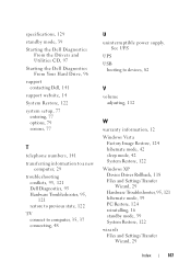
... to computer, 35, 37 connecting, 48 U uninterruptible power supply. specifications, 129 standby mode, 39 Starting the Dell Diagnostics From the Drivers and Utilities CD, 97 Starting the Dell Diagnostics From Your Hard Drive, 96 support contacting Dell, 141 support website, 14 System Restore, 122 system setup... 112 W warranty information, 12 Windows Vista Factory Image Restore, 124 hibernate mode, 42 sleep mode, 42 System Restore, 122 Windows XP Device Driver Rollback, 118 Files and Settings Transfer Wizard, 29 Hardware Troubleshooter, 95, 121 hibernate mode, 39 PC Restore, 124 reinstalling,...
... to computer, 35, 37 connecting, 48 U uninterruptible power supply. specifications, 129 standby mode, 39 Starting the Dell Diagnostics From the Drivers and Utilities CD, 97 Starting the Dell Diagnostics From Your Hard Drive, 96 support contacting Dell, 141 support website, 14 System Restore, 122 system setup... 112 W warranty information, 12 Windows Vista Factory Image Restore, 124 hibernate mode, 42 sleep mode, 42 System Restore, 122 Windows XP Device Driver Rollback, 118 Files and Settings Transfer Wizard, 29 Hardware Troubleshooter, 95, 121 hibernate mode, 39 PC Restore, 124 reinstalling,...
Service Manual
Page 3
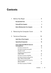
...View of Your Computer 15 System Board Components 16 Power Supply Unit (PSU) DC Connector Pin Assignments 18 DC Power Connector P1 18 DC Power Connector P2 and P3 (Graphics Card 20 DC Power Connectors P4-P7 (HDD0-HDD3 20 DC Power Connector P8 (PHY 21 DC Power Connectors P9 and P10 (Bay1 SATA and Bay2 ...SATA 21 DC Power Connector P11 and P12 (BAY and BAY2 ...
...View of Your Computer 15 System Board Components 16 Power Supply Unit (PSU) DC Connector Pin Assignments 18 DC Power Connector P1 18 DC Power Connector P2 and P3 (Graphics Card 20 DC Power Connectors P4-P7 (HDD0-HDD3 20 DC Power Connector P8 (PHY 21 DC Power Connectors P9 and P10 (Bay1 SATA and Bay2 ...SATA 21 DC Power Connector P11 and P12 (BAY and BAY2 ...
Service Manual
Page 6
9 Processor 83 Removing the Processor 83 Installing the Processor 84 10 System Board 87 Removing the System Board 87 Installing the System Board 88 11 Power Supply 91 Removing the Power Supply 91 Installing the Power Supply 92 12 Front I/O Panel 95 Removing the Front I/O Panel 95 Installing the Front I/O Panel 97 13 Master I/O Board 101 Master I/O Board Components 101 Removing the Master I/O Board 102 Installing the Master I/O Board 103 6 Contents
9 Processor 83 Removing the Processor 83 Installing the Processor 84 10 System Board 87 Removing the System Board 87 Installing the System Board 88 11 Power Supply 91 Removing the Power Supply 91 Installing the Power Supply 92 12 Front I/O Panel 95 Removing the Front I/O Panel 95 Installing the Front I/O Panel 97 13 Master I/O Board 101 Master I/O Board Components 101 Removing the Master I/O Board 102 Installing the Master I/O Board 103 6 Contents
Service Manual
Page 15
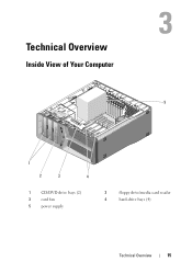
Technical Overview Inside View of Your Computer 5 1 2 3 4 1 CD/DVD drive bays (2) 3 card fan 5 power supply 2 floppy drive/media card reader 4 hard-drive bays (4) Technical Overview 15
Technical Overview Inside View of Your Computer 5 1 2 3 4 1 CD/DVD drive bays (2) 3 card fan 5 power supply 2 floppy drive/media card reader 4 hard-drive bays (4) Technical Overview 15
Service Manual
Page 18
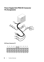
Power Supply Unit (PSU) DC Connector Pin Assignments DC Power Connector P1 13 14 15 16 17 18 19 20 21 22 23 24 1 2 3 4 5 6 7 8 9 10 11 12 18 Technical Overview
Power Supply Unit (PSU) DC Connector Pin Assignments DC Power Connector P1 13 14 15 16 17 18 19 20 21 22 23 24 1 2 3 4 5 6 7 8 9 10 11 12 18 Technical Overview
Service Manual
Page 73
... the cable into the network port or device and then plug it into your computer. 7 Connect your computer and devices to the master I/O board (see "Power Supply Unit (PSU) DC Connector Pin Assignments" on page 18). 5 Replace any full-length expansion cards that you removed (see "Installing PCI and PCI Express Cards...
... the cable into the network port or device and then plug it into your computer. 7 Connect your computer and devices to the master I/O board (see "Power Supply Unit (PSU) DC Connector Pin Assignments" on page 18). 5 Replace any full-length expansion cards that you removed (see "Installing PCI and PCI Express Cards...
Service Manual
Page 74
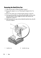
Removing the Hard Drive Fan 1 Follow the procedures in "Before You Begin" on page 9. 2 Remove the computer cover (see "Removing the Computer Cover" on page 13). 3 Remove the card fan cage (see "Removing the Card Fan" on page 69). 4 Disconnect the hard drive fan cable from the FAN_HDD connector on the master I/O board (see "Power Supply Unit (PSU) DC Connector Pin Assignments" on page 18). 5 Slide the hard drive fan cage out from behind the hard drive bays, then lift it from the computer. 2 1 1 hard-drive fan 74 Fans 2 hard-drive fan cage
Removing the Hard Drive Fan 1 Follow the procedures in "Before You Begin" on page 9. 2 Remove the computer cover (see "Removing the Computer Cover" on page 13). 3 Remove the card fan cage (see "Removing the Card Fan" on page 69). 4 Disconnect the hard drive fan cable from the FAN_HDD connector on the master I/O board (see "Power Supply Unit (PSU) DC Connector Pin Assignments" on page 18). 5 Slide the hard drive fan cage out from behind the hard drive bays, then lift it from the computer. 2 1 1 hard-drive fan 74 Fans 2 hard-drive fan cage
Service Manual
Page 77
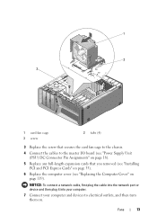
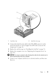
NOTICE: To connect a network cable, first plug the cable into the network port or device and then plug it into your computer. 6 Connect your computer and devices to the FAN_HDD connector on the master I/O board (see "Power Supply Unit (PSU) DC Connector Pin Assignments" on page 18). 4 Replace the card fan cage (see "Installing the Card Fan" on page 71). 5 Replace the computer cover (see "Replacing the Computer Cover" on . 2 1 1 hard drive fan 2 hard drive fan cage 3 Connect the hard drive fan cable to electrical outlets, and then turn them on page 119). Fans 77
NOTICE: To connect a network cable, first plug the cable into the network port or device and then plug it into your computer. 6 Connect your computer and devices to the FAN_HDD connector on the master I/O board (see "Power Supply Unit (PSU) DC Connector Pin Assignments" on page 18). 4 Replace the card fan cage (see "Installing the Card Fan" on page 71). 5 Replace the computer cover (see "Replacing the Computer Cover" on . 2 1 1 hard drive fan 2 hard drive fan cage 3 Connect the hard drive fan cable to electrical outlets, and then turn them on page 119). Fans 77
Service Manual
Page 91
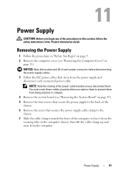
... cable clamp towards the front of the computer to free it from the securing tabs on page 87). 5 Remove the four screws that secure the power supply to prevent them . You must route these cables properly when you replace them to the back of the chassis. 6 Remove the screw that stem ...from the computer. Power Supply 91 NOTICE: Note the location and ID of the procedures in this section, follow the safety instructions in "Before You Begin" on page 9. 2 Remove the...
... cable clamp towards the front of the computer to free it from the securing tabs on page 87). 5 Remove the four screws that secure the power supply to prevent them . You must route these cables properly when you replace them to the back of the chassis. 6 Remove the screw that stem ...from the computer. Power Supply 91 NOTICE: Note the location and ID of the procedures in this section, follow the safety instructions in "Before You Begin" on page 9. 2 Remove the...
Service Manual
Page 92
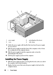
... place, ensuring that secure the power supply to clear the protruding lip of the chassis. 11 Lift the power supply up and out of the computer chassis. 92 Power Supply 1 2 3 4 1 power supply 3 screw 2 protruding lip of the chassis 4 cable clamp 8 Gather the power supply cable bundles that stem from the power supply, for easy removal. 9 Slide the power supply towards the expansion cards, to...
... place, ensuring that secure the power supply to clear the protruding lip of the chassis. 11 Lift the power supply up and out of the computer chassis. 92 Power Supply 1 2 3 4 1 power supply 3 screw 2 protruding lip of the chassis 4 cable clamp 8 Gather the power supply cable bundles that stem from the power supply, for easy removal. 9 Slide the power supply towards the expansion cards, to...
Service Manual
Page 93
...to the chassis. 6 Replace the system board (see "Installing the System Board" on page 88). 7 Reattach each of the DC power cables that secures the cable clamp to electrical outlets, and then turn them . 8 Replace the computer cover (see "Replacing the Computer... Cover" on . 3 Reroute the DC power cables as you found them. 4 Insert the tab along the bottom of the cable clamp into the corresponding slot on the... were previously connected, carefully rerouting them as you found them on page 119). Power Supply 93
...to the chassis. 6 Replace the system board (see "Installing the System Board" on page 88). 7 Reattach each of the DC power cables that secures the cable clamp to electrical outlets, and then turn them . 8 Replace the computer cover (see "Replacing the Computer... Cover" on . 3 Reroute the DC power cables as you found them. 4 Insert the tab along the bottom of the cable clamp into the corresponding slot on the... were previously connected, carefully rerouting them as you found them on page 119). Power Supply 93


