Owner's Manual
Page 1
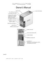
Dell™ Dimension™ 9150 Owner's Manual Service Tag CD or DVD eject button CD or DVD activity light FlexBays (2) for optional floppy drive or optional Media Card Reader microphone connector headphone connector diagnostic lights hard-drive activity light power button USB 2.0 connectors (2) cover latch release power connector sound-card connectors (5) network adapter USB 2.0 connectors (5) card slots for PCI Express x1 (1), PCI Express x16 (1), PCI Express x4 (1), PCI (3) Model DCTA www.dell.com | support.dell.com
Dell™ Dimension™ 9150 Owner's Manual Service Tag CD or DVD eject button CD or DVD activity light FlexBays (2) for optional floppy drive or optional Media Card Reader microphone connector headphone connector diagnostic lights hard-drive activity light power button USB 2.0 connectors (2) cover latch release power connector sound-card connectors (5) network adapter USB 2.0 connectors (5) card slots for PCI Express x1 (1), PCI Express x16 (1), PCI Express x4 (1), PCI (3) Model DCTA www.dell.com | support.dell.com

Owner's Manual
Page 3
Contents Finding Information 9 1 Setting Up and Using Your Computer 13 Setting Up a Printer 13 Printer Cable 13 Connecting a USB Printer 14 Connecting to the Internet 14 Setting Up Your Internet Connection 15 Playing CDs and DVDs 16 Adjusting the Volume 17 Adjusting the Picture ...
Contents Finding Information 9 1 Setting Up and Using Your Computer 13 Setting Up a Printer 13 Printer Cable 13 Connecting a USB Printer 14 Connecting to the Internet 14 Setting Up Your Internet Connection 15 Playing CDs and DVDs 16 Adjusting the Volume 17 Adjusting the Picture ...
Owner's Manual
Page 11
... NOTE: Select your operating system and support for components, such at premier.support.dell.com. Upgrade information for Dell™ 3.5-inch USB floppy drives, Intel® Pentium® M processors, optical drives, and USB devices. Certified drivers, patches, and software updates • Desktop System Software (DSS)- DSS provides critical updates for your region to System...
... NOTE: Select your operating system and support for components, such at premier.support.dell.com. Upgrade information for Dell™ 3.5-inch USB floppy drives, Intel® Pentium® M processors, optical drives, and USB devices. Certified drivers, patches, and software updates • Desktop System Software (DSS)- DSS provides critical updates for your region to System...

Owner's Manual
Page 13
See the documentation that it is compatible with a USB cable. If you purchased a printer cable at the same time you purchased your printer. Setting Up and Using Your Computer 13 Setting Up and Using ...
See the documentation that it is compatible with a USB cable. If you purchased a printer cable at the same time you purchased your printer. Setting Up and Using Your Computer 13 Setting Up and Using ...
Owner's Manual
Page 14
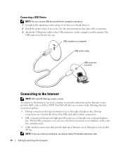
... the printer. With a DSL connection, you need an add-in PCI modem expansion card. 14 Setting Up and Using Your Computer The USB connectors fit only one or more of the following Internet connection options: • Dial-up connections that provide high-speed Internet access through...the operating system setup, if you need a modem or network connection and an Internet service provider (ISP), such as AOL or MSN. Connecting a USB Printer NOTE: You can access the Internet and use a dial-up connections are considerably slower than DSL and cable modem connections. • DSL ...
... the printer. With a DSL connection, you need an add-in PCI modem expansion card. 14 Setting Up and Using Your Computer The USB connectors fit only one or more of the following Internet connection options: • Dial-up connections that provide high-speed Internet access through...the operating system setup, if you need a modem or network connection and an Internet service provider (ISP), such as AOL or MSN. Connecting a USB Printer NOTE: You can access the Internet and use a dial-up connections are considerably slower than DSL and cable modem connections. • DSL ...

Owner's Manual
Page 48
... documentation for setup and troubleshooting information. NOTE: If you need technical assistance for your scanner is USB. See the scanner documentation for cable connection information. • Ensure that your printer, contact the printer's manufacturer. U N L O C K T H E S C A N N E R - For a USB printer, ensure that the electrical outlet is listed, right-click the printer icon. 3 Click Properties and...
... documentation for setup and troubleshooting information. NOTE: If you need technical assistance for your scanner is USB. See the scanner documentation for cable connection information. • Ensure that your printer, contact the printer's manufacturer. U N L O C K T H E S C A N N E R - For a USB printer, ensure that the electrical outlet is listed, right-click the printer icon. 3 Click Properties and...
Owner's Manual
Page 54
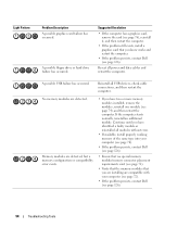
...works and restart the computer. • If the problem persists, contact Dell (see page 74), and then restart the computer. If the computer starts normally, reinstall an additional module. Reseat all USB devices, check cable connections, and then restart the computer. No memory ...modules are compatible with your computer (see page 72). • If the problem persists, contact Dell (see page 126). 54 Troubleshooting Tools Suggested Resolution ...
...works and restart the computer. • If the problem persists, contact Dell (see page 74), and then restart the computer. If the computer starts normally, reinstall an additional module. Reseat all USB devices, check cable connections, and then restart the computer. No memory ...modules are compatible with your computer (see page 72). • If the problem persists, contact Dell (see page 126). 54 Troubleshooting Tools Suggested Resolution ...

Owner's Manual
Page 66
...player is on the diagnostic code. It is adequately ventilated. For adequate cooling, do not use the back USB connectors for devices that you access the Dell Support website or call technical support. 66 Removing and Installing Parts NOTICE: Keep the vent area clean and dust...-free to the system. 5 IEEE 1394 connector (optional) 6 vents 7 USB 2.0 connectors (2) 8 power button 9 hard-drive activity light 10 diagnostic ...
...player is on the diagnostic code. It is adequately ventilated. For adequate cooling, do not use the back USB connectors for devices that you access the Dell Support website or call technical support. 66 Removing and Installing Parts NOTICE: Keep the vent area clean and dust...-free to the system. 5 IEEE 1394 connector (optional) 6 vents 7 USB 2.0 connectors (2) 8 power button 9 hard-drive activity light 10 diagnostic ...

Owner's Manual
Page 68
...ground yourself by touching an unpainted metal surface, such as the metal at least 30 cm (1 ft) of desk top space. 3 network connector 4 USB 2.0 connectors (5) 5 card slots (6) To attach your computer to a network or broadband device, connect one end of a network cable to dissipate any ..., periodically touch an unpainted metal surface to either the computer or the surface on the card. While you use the front USB connectors for bootable USB devices. Removing the Computer Cover CAUTION: Before you connect occasionally, such as printers and keyboards. It is recommended that you ...
...ground yourself by touching an unpainted metal surface, such as the metal at least 30 cm (1 ft) of desk top space. 3 network connector 4 USB 2.0 connectors (5) 5 card slots (6) To attach your computer to a network or broadband device, connect one end of a network cable to dissipate any ..., periodically touch an unpainted metal surface to either the computer or the surface on the card. While you use the front USB connectors for bootable USB devices. Removing the Computer Cover CAUTION: Before you connect occasionally, such as printers and keyboards. It is recommended that you ...
Owner's Manual
Page 71
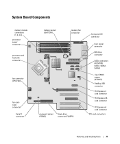
... (PSWD) floppy drive connector (FLOPPY) front panel I/O connector main power connector IDE drive connector SATA connectors (4) (SATA0, SATA1, SATA2, SATA3) clear CMOS jumper (RTCRST) FlexBay USB connector PCI Express x1 card connector PCI Express x16 card connector PCI Express x4 card connector PCI card connectors Removing and Installing Parts 71
... (PSWD) floppy drive connector (FLOPPY) front panel I/O connector main power connector IDE drive connector SATA connectors (4) (SATA0, SATA1, SATA2, SATA3) clear CMOS jumper (RTCRST) FlexBay USB connector PCI Express x1 card connector PCI Express x16 card connector PCI Express x4 card connector PCI card connectors Removing and Installing Parts 71

Owner's Manual
Page 99
... computers. Removing a Media Card Reader CAUTION: Before you touch any of the procedures in this section, follow the safety instructions in the Product Information Guide. USB cable *Media Card Reader *Not present on page 20. Media Card Reader For information on using the Media Card Reader, see page 89). NOTICE: To...
... computers. Removing a Media Card Reader CAUTION: Before you touch any of the procedures in this section, follow the safety instructions in the Product Information Guide. USB cable *Media Card Reader *Not present on page 20. Media Card Reader For information on using the Media Card Reader, see page 89). NOTICE: To...
Owner's Manual
Page 100
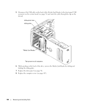
5 Disconnect the USB cable on the back of the drive, remove the Media Card Reader by sliding and holding the sliding plate. 7 Replace the drive panel (see page 91). 8 Replace the computer cover (see page 71) and route the cable through the clip on the system board (see page 107). 100 Removing and Installing Parts sliding plate lever sliding plate *Media Card Reader *Not present on all computers. 6 While pushing on the back of the Media Card Reader to the front panel USB connector on the shroud.
5 Disconnect the USB cable on the back of the drive, remove the Media Card Reader by sliding and holding the sliding plate. 7 Replace the drive panel (see page 91). 8 Replace the computer cover (see page 71) and route the cable through the clip on the system board (see page 107). 100 Removing and Installing Parts sliding plate lever sliding plate *Media Card Reader *Not present on all computers. 6 While pushing on the back of the Media Card Reader to the front panel USB connector on the shroud.

Owner's Manual
Page 102
... begin any of the Media Card Reader and to seat it in the computer. 9 Route the USB cable through the cable routing clip. 10 Replace the computer cover (see page 71). 7 Connect the FlexBay USB cable to the back of the procedures in this section, follow the safety instructions in to the... Media Card Reader connector on all computers. 8 Insert the Media Card Reader into the bay and slide the drive in the Product Information Guide. USB cable *Media Card Reader *Not present on the system board (see page 107).
... begin any of the Media Card Reader and to seat it in the computer. 9 Route the USB cable through the cable routing clip. 10 Replace the computer cover (see page 71). 7 Connect the FlexBay USB cable to the back of the procedures in this section, follow the safety instructions in to the... Media Card Reader connector on all computers. 8 Insert the Media Card Reader into the bay and slide the drive in the Product Information Guide. USB cable *Media Card Reader *Not present on the system board (see page 107).
Owner's Manual
Page 111
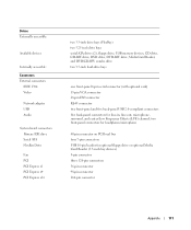
...PCI PCI Express x1 PCI Express x4 PCI Express x16 two 3.5-inch drive bays (FlexBay) two 5.25-inch drive bays serial ATA drives (2), floppy drive, USB memory devices, CD drive, CD-RW drive, DVD drive, DVD-RW drive, Media Card Reader, and DVD/CD-RW combo drive two 3.5-inch hard-...panel 6-pin serial connector (with optional card) 15-pin VGA connector 28-pin DVI connector RJ-45 connector two front-panel and five back-panel USB 2.0-compliant connectors five back-panel connectors for optional floppy drive or optional Media Card Reader (3.5-inch bay devices) 5-pin connector three 120-pin connectors ...
...PCI PCI Express x1 PCI Express x4 PCI Express x16 two 3.5-inch drive bays (FlexBay) two 5.25-inch drive bays serial ATA drives (2), floppy drive, USB memory devices, CD drive, CD-RW drive, DVD drive, DVD-RW drive, Media Card Reader, and DVD/CD-RW combo drive two 3.5-inch hard-...panel 6-pin serial connector (with optional card) 15-pin VGA connector 28-pin DVI connector RJ-45 connector two front-panel and five back-panel USB 2.0-compliant connectors five back-panel connectors for optional floppy drive or optional Media Card Reader (3.5-inch bay devices) 5-pin connector three 120-pin connectors ...
Owner's Manual
Page 116
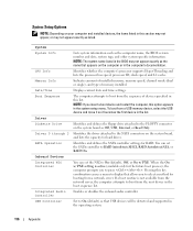
... the NIC to On (default), Off, or On w/ PXE. If a boot routine is active (available only for booting from a USB memory device, select the USB device and move it so it becomes the first device in the system setup menu. CPU Info Identifies whether the computer's processor supports... information. Identifies the drives attached to the SATA connectors on the system board, and lists the capacity for RAID. USB Controller Set to On (default) so that USB devices will be detected and supported in the computer's documentation. Date/Time Displays current date and time settings. System ...
... the NIC to On (default), Off, or On w/ PXE. If a boot routine is active (available only for booting from a USB memory device, select the USB device and move it so it becomes the first device in the system setup menu. CPU Info Identifies whether the computer's processor supports... information. Identifies the drives attached to the SATA connectors on the system board, and lists the capacity for RAID. USB Controller Set to On (default) so that USB devices will be detected and supported in the computer's documentation. Date/Time Displays current date and time settings. System ...

Owner's Manual
Page 117
... the current status of 1MB and 8MB, this option appears in the same way that access to be noisier. Off = Internal USB for the integrated video controller. The hard drive operates at its maximum speed. Appendix 117 This setting specifies which video controller is installed... hard drive to be assigned and verified. The hard drive operates at the level suggested by pressing when the computer starts. USB for FlexBay Video Primary Video Video Memory Size Performance SpeedStep HyperThreading Hard Drive Acoustics Security Admin Password System Password Password Status This ...
... the current status of 1MB and 8MB, this option appears in the same way that access to be noisier. Off = Internal USB for the integrated video controller. The hard drive operates at its maximum speed. Appendix 117 This setting specifies which video controller is installed... hard drive to be assigned and verified. The hard drive operates at the level suggested by pressing when the computer starts. USB for FlexBay Video Primary Video Video Memory Size Performance SpeedStep HyperThreading Hard Drive Acoustics Security Admin Password System Password Password Status This ...
Owner's Manual
Page 119
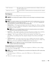
... device is found, the computer generates an error message that your computer to boot from the primary hard drive. The computer attempts to a USB connector (see page 113). 1 If you are booting to boot from the CD drive. Follow the on-screen instructions to display on the...from the floppy drive. If no floppy drive installed, the computer attempts to the next bootable device. • USB Flash Device - Appendix 119 Insert the memory device into a USB port and restart the computer. Boot Sequence This feature allows you modify any boot sequence settings, save the new...
... device is found, the computer generates an error message that your computer to boot from the primary hard drive. The computer attempts to a USB connector (see page 113). 1 If you are booting to boot from the CD drive. Follow the on-screen instructions to display on the...from the floppy drive. If no floppy drive installed, the computer attempts to the next bootable device. • USB Flash Device - Appendix 119 Insert the memory device into a USB port and restart the computer. Boot Sequence This feature allows you modify any boot sequence settings, save the new...
Owner's Manual
Page 120
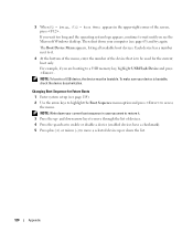
... you want to be bootable. Changing Boot Sequence for the current boot only. and down-arrow keys to access the menu. NOTE: To boot to a USB device, the device must be used for Future Boots 1 Enter system setup (see page 114). 2 Use the arrow keys to highlight the Boot Sequence menu... available boot devices. For example, if you are booting to wait until you wait too long and the operating system logo appears, continue to a USB memory key, highlight USB Flash Device and press . If you see page 63) and try again. Then shut down your device is to restore it. 3 Press the...
... you want to be bootable. Changing Boot Sequence for the current boot only. and down-arrow keys to access the menu. NOTE: To boot to a USB device, the device must be used for Future Boots 1 Enter system setup (see page 114). 2 Use the arrow keys to highlight the Boot Sequence menu... available boot devices. For example, if you are booting to wait until you wait too long and the operating system logo appears, continue to a USB memory key, highlight USB Flash Device and press . If you see page 63) and try again. Then shut down your device is to restore it. 3 Press the...
Owner's Manual
Page 145
...headphone, 66 IEEE 1394, 66 line-in, 67 line-out, 67 microphone, 66-67 network adapter, 68 power, 67 sound, 67 surround, 67 USB, 66, 68 copying CDs general information, 18 helpful tips, 20 how to, 18 copying DVDs general information, 18 helpful tips, 20 how to, ...18 cover replacing, 107 D Dell Dell Diagnostics, 56 support policy, 123 support site, 11 Dell Premier Support website, 9, 11 diagnostic lights, 53 diagnostics Dell, 56 lights, 53, 66 documentation online, 11 Product Information Guide, 9 Setup Diagram, 9 drive panel, ...
...headphone, 66 IEEE 1394, 66 line-in, 67 line-out, 67 microphone, 66-67 network adapter, 68 power, 67 sound, 67 surround, 67 USB, 66, 68 copying CDs general information, 18 helpful tips, 20 how to, 18 copying DVDs general information, 18 helpful tips, 20 how to, ...18 cover replacing, 107 D Dell Dell Diagnostics, 56 support policy, 123 support site, 11 Dell Premier Support website, 9, 11 diagnostic lights, 53 diagnostics Dell, 56 lights, 53, 66 documentation online, 11 Product Information Guide, 9 Setup Diagram, 9 drive panel, ...
Owner's Manual
Page 147
...Setup Wizard, 24 problems, 46 setting up, 23 Network Setup Wizard, 24 O operating system reinstalling Windows XP, 60 P password clearing, 121 jumper, 121 PC Restore, 61 PCI cards removing, 80 PCI Express ...47 Power Options Properties, 25 printer cable, 13 connecting, 13 problems, 48 setting up, 13 USB, 14 problems battery, 37 blue screen, 44 CD drive, 38 CD-RW drive, 39 computer crashes, 43-44 ...computer stops responding, 43 Dell Diagnostics, 56 diagnostic lights, 53 drives, 38 DVD drive, 38 e-mail, 39 error messages, 41 ...
...Setup Wizard, 24 problems, 46 setting up, 23 Network Setup Wizard, 24 O operating system reinstalling Windows XP, 60 P password clearing, 121 jumper, 121 PC Restore, 61 PCI cards removing, 80 PCI Express ...47 Power Options Properties, 25 printer cable, 13 connecting, 13 problems, 48 setting up, 13 USB, 14 problems battery, 37 blue screen, 44 CD drive, 38 CD-RW drive, 39 computer crashes, 43-44 ...computer stops responding, 43 Dell Diagnostics, 56 diagnostic lights, 53 drives, 38 DVD drive, 38 e-mail, 39 error messages, 41 ...

