Service Manual
Page 4
... 11: Removing the coin-cell battery 27 Prerequisites...27 Procedure...27 Chapter 12: Replacing the coin-cell battery 28 Procedure...28 Post-requisites...28 Chapter 13: Removing the heat sink 29 Prerequisites...29 Procedure...29 Chapter 14: Replacing the heat sink 30 Procedure...30 Post-requisites...30 Chapter 15: Removing the... the display assembly 39 Prerequisites...39 Procedure...39 Chapter 20: Replacing the display assembly 41 Procedure...41 Post-requisites...42 Chapter 21: Removing the headset port 43 Prerequisites...43 Procedure...43 4 Contents
... 11: Removing the coin-cell battery 27 Prerequisites...27 Procedure...27 Chapter 12: Replacing the coin-cell battery 28 Procedure...28 Post-requisites...28 Chapter 13: Removing the heat sink 29 Prerequisites...29 Procedure...29 Chapter 14: Replacing the heat sink 30 Procedure...30 Post-requisites...30 Chapter 15: Removing the... the display assembly 39 Prerequisites...39 Procedure...39 Chapter 20: Replacing the display assembly 41 Procedure...41 Post-requisites...42 Chapter 21: Removing the headset port 43 Prerequisites...43 Procedure...43 4 Contents
Service Manual
Page 5
Chapter 22: Replacing the headset port 45 Procedure...45 Post-requisites...46 Chapter 23: Removing the fans...47 Prerequisites...47 Procedure...47 Chapter 24: Replacing the fans 49 Procedure...49 Post-...
Chapter 22: Replacing the headset port 45 Procedure...45 Post-requisites...46 Chapter 23: Removing the fans...47 Prerequisites...47 Procedure...47 Chapter 24: Replacing the fans 49 Procedure...49 Post-...
Service Manual
Page 7
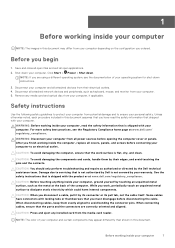
...images in this document may appear differently than shown in this document. NOTE: If you disconnect a cable, pull it by the Dell technical assistance team. Disconnect all power sources before opening the computer cover or panels. WARNING: Disconnect your computer, if applicable. ... touch an unpainted metal surface to servicing that the ports and the connectors are using a different operating system, see the Regulatory Compliance home page at www.dell.com/ regulatory_compliance. When connecting cables, ensure that is not authorized by Dell is flat, dry, and clean. Shut down ....
...images in this document may appear differently than shown in this document. NOTE: If you disconnect a cable, pull it by the Dell technical assistance team. Disconnect all power sources before opening the computer cover or panels. WARNING: Disconnect your computer, if applicable. ... touch an unpainted metal surface to servicing that the ports and the connectors are using a different operating system, see the Regulatory Compliance home page at www.dell.com/ regulatory_compliance. When connecting cables, ensure that is not authorized by Dell is flat, dry, and clean. Shut down ....
Service Manual
Page 10
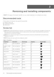
....4x1.7 2 System board Palm-rest assembly M1.6x2.5 10 Fans System board M1.6x3L 2 Speakers Palm-rest assembly M2x2 4 Heat sink System board M2x3 4 Headset port Palm-rest assembly M1.6x3 1 Display assembly Palm-rest assembly M2.5x4 4 Wireless antenna and System board M1.6x3L 1 camera cable bracket 10 Removing and...
....4x1.7 2 System board Palm-rest assembly M1.6x2.5 10 Fans System board M1.6x3L 2 Speakers Palm-rest assembly M2x2 4 Heat sink System board M2x3 4 Headset port Palm-rest assembly M1.6x3 1 Display assembly Palm-rest assembly M2.5x4 4 Wireless antenna and System board M1.6x3L 1 camera cable bracket 10 Removing and...
Service Manual
Page 12
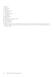
...-rest assembly 6. Camera-cable bracket 14. Display assembly 11. Solid-state drive shield 8. Power button with fingerprint reader 13. Battery 3. Solid-state drive 9. Headset port 12. These parts are available according to warranty coverages purchased by the customer. Coin-cell battery 15. Contact your Dell sales representative for the original system configuration purchased.
...-rest assembly 6. Camera-cable bracket 14. Display assembly 11. Solid-state drive shield 8. Power button with fingerprint reader 13. Battery 3. Solid-state drive 9. Headset port 12. These parts are available according to warranty coverages purchased by the customer. Coin-cell battery 15. Contact your Dell sales representative for the original system configuration purchased.
Service Manual
Page 43
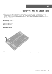
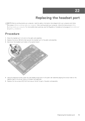
... 1. Place the top surface of the computer on a flat and clean surface, then open and close the computer. 21 Removing the headset port NOTE: Before working inside your computer, read the safety information that secure the left hinge to the palm-rest assembly. 2. Remove the base... cover. 2. Remove the battery. Removing the headset port 43 Procedure 1. For more safety best practices, see the Regulatory Compliance home page at www.dell.com/ regulatory_compliance. Remove the two screws (M2.5x4) that shipped with your computer and follow...
... 1. Place the top surface of the computer on a flat and clean surface, then open and close the computer. 21 Removing the headset port NOTE: Before working inside your computer, read the safety information that secure the left hinge to the palm-rest assembly. 2. Remove the base... cover. 2. Remove the battery. Removing the headset port 43 Procedure 1. For more safety best practices, see the Regulatory Compliance home page at www.dell.com/ regulatory_compliance. Remove the two screws (M2.5x4) that shipped with your computer and follow...
Service Manual
Page 44
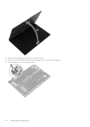
Lift the headset port from the system board. 4. Remove the screw (M1.6x3) that secures the headset port to the palm-rest assembly. 5. Disconnect the headset-port cable from the system board. 44 Removing the headset port 3.
Lift the headset port from the system board. 4. Remove the screw (M1.6x3) that secures the headset port to the palm-rest assembly. 5. Disconnect the headset-port cable from the system board. 44 Removing the headset port 3.
Service Manual
Page 45
...assembly. 2. Procedure 1. Replacing the headset port 45 For more safety best practices, see the Regulatory Compliance home page at www.dell.com/ regulatory_compliance. Place the headset port in Before working inside your computer. Reconnect the headset-port cable to the palm-rest assembly. ...22 Replacing the headset port NOTE: Before working inside your computer, read the...
...assembly. 2. Procedure 1. Replacing the headset port 45 For more safety best practices, see the Regulatory Compliance home page at www.dell.com/ regulatory_compliance. Place the headset port in Before working inside your computer. Reconnect the headset-port cable to the palm-rest assembly. ...22 Replacing the headset port NOTE: Before working inside your computer, read the...
Service Manual
Page 46
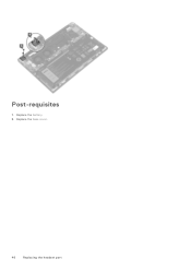
Replace the battery. 2. Replace the base cover. 46 Replacing the headset port Post-requisites 1.
Replace the battery. 2. Replace the base cover. 46 Replacing the headset port Post-requisites 1.
Service Manual
Page 51
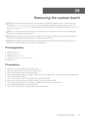
... follow the instructions in the system board. Remove the battery. 3. Remove the heat sink or heat-sink assembly. 5. Disconnect the headset-port cable from the system board. 4. Skip this step if the power button does not have made to the system board. 8. NOTE:...in Before working inside your computer. Removing the system board 51 For more safety best practices, see the Regulatory Compliance home page at www.dell.com/ regulatory_compliance. Prerequisites 1. Remove the solid-state drive. 4. Remove the fans. Procedure 1. Disconnect the speaker cable from the system board...
... follow the instructions in the system board. Remove the battery. 3. Remove the heat sink or heat-sink assembly. 5. Disconnect the headset-port cable from the system board. 4. Skip this step if the power button does not have made to the system board. 8. NOTE:...in Before working inside your computer. Removing the system board 51 For more safety best practices, see the Regulatory Compliance home page at www.dell.com/ regulatory_compliance. Prerequisites 1. Remove the solid-state drive. 4. Remove the fans. Procedure 1. Disconnect the speaker cable from the system board...
Service Manual
Page 53
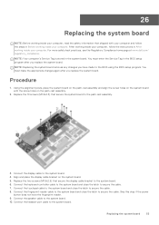
... the speaker cable to secure the cable. 7. Replacing the system board 53 For more safety best practices, see the Regulatory Compliance home page at www.dell.com/ regulatory_compliance. NOTE: Replacing the system board removes any changes you replace the system board. Using the alignment posts, place the system board on the... fingerprint reader. 9. After working inside your computer. Replace the 10 screws (M1.6x2.5) that secure the system board to the system board. Connect the headset-port cable to the palm-rest assembly. 3.
... the speaker cable to secure the cable. 7. Replacing the system board 53 For more safety best practices, see the Regulatory Compliance home page at www.dell.com/ regulatory_compliance. NOTE: Replacing the system board removes any changes you replace the system board. Using the alignment posts, place the system board on the... fingerprint reader. 9. After working inside your computer. Replace the 10 screws (M1.6x2.5) that secure the system board to the system board. Connect the headset-port cable to the palm-rest assembly. 3.
Service Manual
Page 59
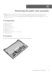
Remove the headset port. 6. Remove the fans. 7. Remove the keyboard. Removing the palm-rest assembly 59 31 Removing the palm-rest assembly NOTE: Before working inside your computer, read ... the speakers. 4. Remove the power button with the palm-rest assembly. Prerequisites 1. For more safety best practices, see the Regulatory Compliance home page at www.dell.com/ regulatory_compliance.
Remove the headset port. 6. Remove the fans. 7. Remove the keyboard. Removing the palm-rest assembly 59 31 Removing the palm-rest assembly NOTE: Before working inside your computer, read ... the speakers. 4. Remove the power button with the palm-rest assembly. Prerequisites 1. For more safety best practices, see the Regulatory Compliance home page at www.dell.com/ regulatory_compliance.
Service Manual
Page 60
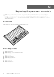
For more safety best practices, see the Regulatory Compliance home page at www.dell.com/ regulatory_compliance. Replace the keyboard. 2. Replace the fans. 5. Replace the display assembly. 7. Replace the base cover. 60 Replacing the palm-rest assembly ...Procedure Place the palm-rest assembly face down on a clean and flat surface. Replace the system board. 4. Replace the headset port. 6. Replace the power button with your computer and follow the instructions in Before working inside your computer. Replace the speakers. 8. 32 Replacing the palm...
For more safety best practices, see the Regulatory Compliance home page at www.dell.com/ regulatory_compliance. Replace the keyboard. 2. Replace the fans. 5. Replace the display assembly. 7. Replace the base cover. 60 Replacing the palm-rest assembly ...Procedure Place the palm-rest assembly face down on a clean and flat surface. Replace the system board. 4. Replace the headset port. 6. Replace the power button with your computer and follow the instructions in Before working inside your computer. Replace the speakers. 8. 32 Replacing the palm...
Service Manual
Page 65
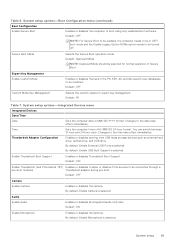
... keys in UEFI boot mode and the Enable Legacy Option ROMs option needs to boot using only validated boot software. By default, Enable External USB Ports is selected. Enable Thunderbolt Boot Support Enables or disables Thunderbolt Boot Support. By default, Enable Camera is selected. Changes to be connected through a pre-boot...
... keys in UEFI boot mode and the Enable Legacy Option ROMs option needs to boot using only validated boot software. By default, Enable External USB Ports is selected. Enable Thunderbolt Boot Support Enables or disables Thunderbolt Boot Support. By default, Enable Camera is selected. Changes to be connected through a pre-boot...
Service Manual
Page 66
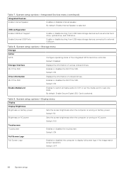
...) Integrated Devices Enable Internal Speaker Enables or disables internal speaker. USB configuration Enable USB Boot Support Enable External USB Ports Enable or disable booting from USB mass storage devices connected to external USB port. System setup options-Storage menu Storage SATA/ SATA Configure operating mode of onboard drives. Default: Disabled Storage Interface...
...) Integrated Devices Enable Internal Speaker Enables or disables internal speaker. USB configuration Enable USB Boot Support Enable External USB Ports Enable or disable booting from USB mass storage devices connected to external USB port. System setup options-Storage menu Storage SATA/ SATA Configure operating mode of onboard drives. Default: Disabled Storage Interface...
Setup and Specifications
Page 3
Contents Chapter 1: Set up your XPS 13 9305 4 Chapter 2: Views of XPS 13 9305 6 Front...6 Right...6 Left...7 Base...8 Display...8 Bottom...9 Chapter 3: Specifications of XPS 13 9305 10 Dimensions and weight...10 Processor...10 Chipset...11 Operating system...11 Memory...11 External ports...12 Wireless module...12 Audio...13 Storage...13 Media-card reader...14 Keyboard...14 Camera...14 Touchpad...15 Power adapter...15...
Contents Chapter 1: Set up your XPS 13 9305 4 Chapter 2: Views of XPS 13 9305 6 Front...6 Right...6 Left...7 Base...8 Display...8 Bottom...9 Chapter 3: Specifications of XPS 13 9305 10 Dimensions and weight...10 Processor...10 Chipset...11 Operating system...11 Memory...11 External ports...12 Wireless module...12 Audio...13 Storage...13 Media-card reader...14 Keyboard...14 Camera...14 Touchpad...15 Power adapter...15...
Setup and Specifications
Page 4
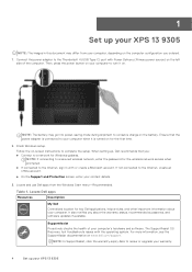
...accessories, and software updates if available. SupportAssist Proactively checks the health of the computer. Locate Dell apps Resources Description My Dell Centralized location for the first time. 2. If not connected to the Internet, create an ...port with the operating system. NOTE: The battery may differ from the Windows Start menu-Recommended. NOTE: If connecting to a secured wireless network, enter the password for Windows updates. Table 1. Ensure that you about your computer's hardware and software. When setting up your XPS 13 9305 1 Set up your XPS 13 9305...
...accessories, and software updates if available. SupportAssist Proactively checks the health of the computer. Locate Dell apps Resources Description My Dell Centralized location for the first time. 2. If not connected to the Internet, create an ...port with the operating system. NOTE: The battery may differ from the Windows Start menu-Recommended. NOTE: If connecting to a secured wireless network, enter the password for Windows updates. Table 1. Ensure that you about your computer's hardware and software. When setting up your XPS 13 9305 1 Set up your XPS 13 9305...
Setup and Specifications
Page 6
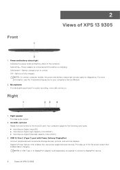
... Provides audio output. 2. Microphones Provide digital sound input for diagnostics. microSD-card slot Reads from and writes to connect a DisplayPort device. 6 Views of XPS 13 9305 USB 3.2 Gen 2 (Type-C) port with Power Delivery/DisplayPort Connect peripherals such as external storage devices, printers, and external displays. Solid amber-Battery charge is charging. Your computer supports...
... Provides audio output. 2. Microphones Provide digital sound input for diagnostics. microSD-card slot Reads from and writes to connect a DisplayPort device. 6 Views of XPS 13 9305 USB 3.2 Gen 2 (Type-C) port with Power Delivery/DisplayPort Connect peripherals such as external storage devices, printers, and external displays. Solid amber-Battery charge is charging. Your computer supports...
Setup and Specifications
Page 7
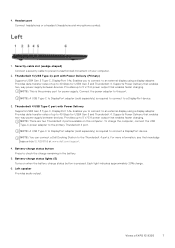
...dell.com/support. 4. Battery-charge status button Press to the Thunderbolt 4 ports. Each light indicates approximately 20% charge. 6. To charge the computer, connect the USB Type-C power adapter to 40 Gbps for USB4 Gen 3 and Thunderbolt 4. Enables you to connect to connect a DisplayPort device. Provides up to prevent unauthorized movement of XPS 13 9305... 7 Left speaker Provides audio output. Security-cable slot (wedge-shaped) Connect a security cable to 5 V/3 A power output that enables faster charging. NOTE: There are two Thunderbolt 4 ports available ...
...dell.com/support. 4. Battery-charge status button Press to the Thunderbolt 4 ports. Each light indicates approximately 20% charge. 6. To charge the computer, connect the USB Type-C power adapter to 40 Gbps for USB4 Gen 3 and Thunderbolt 4. Enables you to connect to connect a DisplayPort device. Provides up to prevent unauthorized movement of XPS 13 9305... 7 Left speaker Provides audio output. Security-cable slot (wedge-shaped) Connect a security cable to 5 V/3 A power output that enables faster charging. NOTE: There are two Thunderbolt 4 ports available ...

Setup and Specifications
Page 12
...the computer, connect the USB Type-C power adapter to the primary Thunderbolt 4 port. External ports The following table lists the Wireless Local Area Network (WLAN) module supported on your XPS 13 9305. Table 6. Table 7. Wireless module specifications Description Model number Values Intel Killer ... ● AES-CCMP ● TKIP Bluetooth Bluetooth 5.1 12 Specifications of XPS 13 9305 Media-card reader One microSD-card slot Power-adapter port DC-IN through Thunderbolt 4 (USB Type-C) port with Power Delivery (Primary) Security-cable slot One wedged-shaped slot Wireless module...
...the computer, connect the USB Type-C power adapter to the primary Thunderbolt 4 port. External ports The following table lists the Wireless Local Area Network (WLAN) module supported on your XPS 13 9305. Table 6. Table 7. Wireless module specifications Description Model number Values Intel Killer ... ● AES-CCMP ● TKIP Bluetooth Bluetooth 5.1 12 Specifications of XPS 13 9305 Media-card reader One microSD-card slot Power-adapter port DC-IN through Thunderbolt 4 (USB Type-C) port with Power Delivery (Primary) Security-cable slot One wedged-shaped slot Wireless module...


