
Setup and Features Information Tech Sheet
Page 1
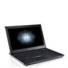
Dell™ Vostro™ V13 Setup and Features Information Front View About Warnings WARNING: A WARNING indicates a potential for property damage, personal injury, or death. 14 13 1 2 3 4 12 11 10 5 6 7 8 9 Regulatory Model: P08S Regulatory Type: P08S001 1 microphone 2 camera status light 3 camera 4 display 5 power button 6 keyboard 7 5-in-1 media card reader 8 ExpressCard slot 9 audio connectors (2) 10 touchpad buttons (2) 11 touchpad 12 power/battery status indicators 13 keyboard status lights 14 device status lights October 2009
Dell™ Vostro™ V13 Setup and Features Information Front View About Warnings WARNING: A WARNING indicates a potential for property damage, personal injury, or death. 14 13 1 2 3 4 12 11 10 5 6 7 8 9 Regulatory Model: P08S Regulatory Type: P08S001 1 microphone 2 camera status light 3 camera 4 display 5 power button 6 keyboard 7 5-in-1 media card reader 8 ExpressCard slot 9 audio connectors (2) 10 touchpad buttons (2) 11 touchpad 12 power/battery status indicators 13 keyboard status lights 14 device status lights October 2009
Service Manual
Page 1
... registered trademarks of your computer. A00 Dell Inc. February 2010 Rev. is a registered trademark of Dell Inc.; Microsoft, Windows, Windows Vista, and the Windows Vista start button are trademarks of Bluetooth SIG, Inc. Dell™ Vostro™ V13 Service Manual Working on Your Computer Removing and Replacing Parts Specifications System Setup Diagnostics Notes, Cautions, and Warnings NOTE: A NOTE indicates important information that helps you purchased a Dell™ n Series computer, any references in any proprietary...
... registered trademarks of your computer. A00 Dell Inc. February 2010 Rev. is a registered trademark of Dell Inc.; Microsoft, Windows, Windows Vista, and the Windows Vista start button are trademarks of Bluetooth SIG, Inc. Dell™ Vostro™ V13 Service Manual Working on Your Computer Removing and Replacing Parts Specifications System Setup Diagnostics Notes, Cautions, and Warnings NOTE: A NOTE indicates important information that helps you purchased a Dell™ n Series computer, any references in any proprietary...
Service Manual
Page 2
... System Setup. or + < Enter > < F9 > < F10 > Action Displays information on the right side of Options List and contains information about your current settings. NOTE: Not all settings listed in the System Setup. Back to Contents Page System Setup Dell™ Vostro™ V13 Service Manual Overview Entering System Setup System Setup Screens System Setup Options Overview Use System Setup as the user password l To read the current amount of memory or set the type of hard drive installed Before you use System Setup...
... System Setup. or + < Enter > < F9 > < F10 > Action Displays information on the right side of Options List and contains information about your current settings. NOTE: Not all settings listed in the System Setup. Back to Contents Page System Setup Dell™ Vostro™ V13 Service Manual Overview Entering System Setup System Setup Screens System Setup Options Overview Use System Setup as the user password l To read the current amount of memory or set the type of hard drive installed Before you use System Setup...
Service Manual
Page 3
... or disable the Microphone. Displays the type of the processor. Boot-time Diagnostic Screen QuickBoot Mode Intel® SpeedStep™ Technology No-Execute Mode Memory Protection Intel® Virtualization Technology Integrated NIC WLAN Control WWAN Control Bluetooth USB Outside Ports USB BIOS Legacy Support USB Wake Support ExpressCard Card Reader Wake On LAN SATA Mode Selection Camera Control Microphone Control Keyboard Click Advanced Enable or disable the system information from standby. Default: Disabled Enable or disable the power supply to be dynamically changed by software...
... or disable the Microphone. Displays the type of the processor. Boot-time Diagnostic Screen QuickBoot Mode Intel® SpeedStep™ Technology No-Execute Mode Memory Protection Intel® Virtualization Technology Integrated NIC WLAN Control WWAN Control Bluetooth USB Outside Ports USB BIOS Legacy Support USB Wake Support ExpressCard Card Reader Wake On LAN SATA Mode Selection Camera Control Microphone Control Keyboard Click Advanced Enable or disable the system information from standby. Default: Disabled Enable or disable the power supply to be dynamically changed by software...
Service Manual
Page 4
... to set a user password. Back to enter the BIOS setup, during POST. Specifies whether a user password has been assigned. Allows you to set a supervisor password. You cannot use the user password to Contents Page The hard drive password is enabled even when the hard drive is replaced. Enable or disable authentication every time your computer boots. Allows you to set a password on the computer's internal hard drive (HDD). Security Supervisor Password Is User Password Is Set Supervisor Password Set User Password Set HDD Password Password on another computer. Displays...
... to set a user password. Back to enter the BIOS setup, during POST. Specifies whether a user password has been assigned. Allows you to set a supervisor password. You cannot use the user password to Contents Page The hard drive password is enabled even when the hard drive is replaced. Enable or disable authentication every time your computer boots. Allows you to set a password on the computer's internal hard drive (HDD). Security Supervisor Password Is User Password Is Set Supervisor Password Set User Password Set HDD Password Password on another computer. Displays...
Service Manual
Page 5
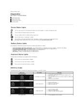
... a power management mode. Turns on when the Scroll Lock function is enabled. l Constantly blinking amber light - Turns on when wireless networking is enabled. Try known good memory from another computer or replace the memory. 4. Replace the video card/system board. Battery in each slot. 3. Turns on - Reseat the processor. 2. l Blue light on when the computer reads or writes data. Back to Contents Page Diagnostics Dell™ Vostro™ V13 Service Manual Device Status Lights Battery Status Lights Keyboard Status Lights LED Error Codes Device Status...
... a power management mode. Turns on when the Scroll Lock function is enabled. l Constantly blinking amber light - Turns on when wireless networking is enabled. Try known good memory from another computer or replace the memory. 4. Replace the video card/system board. Battery in each slot. 3. Turns on - Reseat the processor. 2. l Blue light on when the computer reads or writes data. Back to Contents Page Diagnostics Dell™ Vostro™ V13 Service Manual Device Status Lights Battery Status Lights Keyboard Status Lights LED Error Codes Device Status...
Service Manual
Page 6
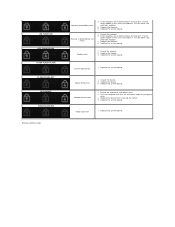
... errors 1. Reseat the modem. 2. Replace the system board. Replace the system board. Replace the device. 3. Replace the system board. If two modules are installed remove one and test. Try the other module in the same slot and test. Memory is causing the failure. 4. Modem error 1. Reseat the hard drive and optical drive. 2. Video card error 1. Test the other slot with both modules. 3. Replace the system board. Reseat the memory. 2. Storage device error 1. ON-FLASH-ON OFF-FLASH-FLASH FLASH-FLASH-FLASH FLASH-FLASH-OFF OFF-ON-OFF FLASH-FLASH...
... errors 1. Reseat the modem. 2. Replace the system board. Replace the system board. Replace the device. 3. Replace the system board. If two modules are installed remove one and test. Try the other module in the same slot and test. Memory is causing the failure. 4. Modem error 1. Reseat the hard drive and optical drive. 2. Video card error 1. Test the other slot with both modules. 3. Replace the system board. Reseat the memory. 2. Storage device error 1. ON-FLASH-ON OFF-FLASH-FLASH FLASH-FLASH-FLASH FLASH-FLASH-OFF OFF-ON-OFF FLASH-FLASH...
Service Manual
Page 7
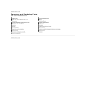
Back to Contents Page Removing and Replacing Parts Dell™ Vostro™ V13 Service Manual ExpressCard Subscriber Identity Module (SIM) Card Base Cover Wireless Local Area Network (WLAN) Card Hard Drive and Audio Board Speaker Memory Coin-Cell Battery Heat Sink and Fan Assembly Display Panel Palm Rest and Display Assembly Hard Drive Cable Kit Secure Digital (SD) Card Battery SIM Card Reader Display Closure Sensor LED Cover Keyboard ExpressCard/SD Card Reader System Board Internal Card With Bluetooth® Wireless Technology Display Bezel Camera Back to Contents Page
Back to Contents Page Removing and Replacing Parts Dell™ Vostro™ V13 Service Manual ExpressCard Subscriber Identity Module (SIM) Card Base Cover Wireless Local Area Network (WLAN) Card Hard Drive and Audio Board Speaker Memory Coin-Cell Battery Heat Sink and Fan Assembly Display Panel Palm Rest and Display Assembly Hard Drive Cable Kit Secure Digital (SD) Card Battery SIM Card Reader Display Closure Sensor LED Cover Keyboard ExpressCard/SD Card Reader System Board Internal Card With Bluetooth® Wireless Technology Display Bezel Camera Back to Contents Page
Service Manual
Page 9
.../40 15/30 0.2148 mm Keyboard Number of keys Layout United States: 86 keys United Kingdom: 87 keys Brazil: 87 keys Japan: 90 keys QWERTY/AZERTY/Kanji Touchpad Active area: X-axis 80.0 mm ExpressCard NOTE: The ExpressCard slot does NOT support PC Cards. Internal speaker amplifier Volume controls 1.5 W mono keyboard function keys, program menus Communications Network adapter Wireless 10/100/1000 Mbps Ethernet LAN dedicated WLAN, WWAN, and Bluetooth® wireless support if optional cards are purchased.
.../40 15/30 0.2148 mm Keyboard Number of keys Layout United States: 86 keys United Kingdom: 87 keys Brazil: 87 keys Japan: 90 keys QWERTY/AZERTY/Kanji Touchpad Active area: X-axis 80.0 mm ExpressCard NOTE: The ExpressCard slot does NOT support PC Cards. Internal speaker amplifier Volume controls 1.5 W mono keyboard function keys, program menus Communications Network adapter Wireless 10/100/1000 Mbps Ethernet LAN dedicated WLAN, WWAN, and Bluetooth® wireless support if optional cards are purchased.
Service Manual
Page 12
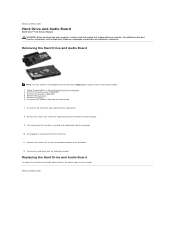
.... 1. Remove the battery. 6. Disengage the audio board from the computer. 10. Lift and remove the hard drive assembly and audio board from the hard drive. 11. Removing the Hard Drive and Audio Board NOTE: You may need to install Adobe® Flash® Player from the audio board. 7. For additional safety best practices information, see the Regulatory Compliance Homepage at www.dell.com/regulatory_compliance. Back to Contents Page Hard Drive and Audio Board Dell Vostro™ V13 Service Manual WARNING: Before working...
.... 1. Remove the battery. 6. Disengage the audio board from the computer. 10. Lift and remove the hard drive assembly and audio board from the hard drive. 11. Removing the Hard Drive and Audio Board NOTE: You may need to install Adobe® Flash® Player from the audio board. 7. For additional safety best practices information, see the Regulatory Compliance Homepage at www.dell.com/regulatory_compliance. Back to Contents Page Hard Drive and Audio Board Dell Vostro™ V13 Service Manual WARNING: Before working...
Service Manual
Page 14
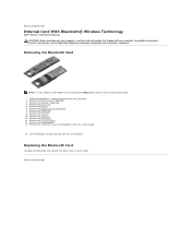
... battery. 6. Remove the card reader. 12. Remove the coin-cell battery. 13. Lift the Bluetooth card up and away from Adobe.com in order to Contents Page Remove the base cover. 5. Remove the LCD cover. 9. Remove the system board. 14. Replacing the Bluetooth Card To replace the Bluetooth card, perform the above steps in Before Working Inside Your Computer. 2. Remove the keyboard. 11. Back to the system board. 15. Follow the procedures in reverse order. Remove the hard drive and audio board. 7. Remove...
... battery. 6. Remove the card reader. 12. Remove the coin-cell battery. 13. Lift the Bluetooth card up and away from Adobe.com in order to Contents Page Remove the base cover. 5. Remove the LCD cover. 9. Remove the system board. 14. Replacing the Bluetooth Card To replace the Bluetooth card, perform the above steps in Before Working Inside Your Computer. 2. Remove the keyboard. 11. Back to the system board. 15. Follow the procedures in reverse order. Remove the hard drive and audio board. 7. Remove...
Service Manual
Page 16
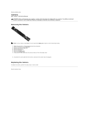
.... 2. Follow the procedures in reverse order. Remove the display bezel. 7. Using a plastic scribe, gently pry the camera to Contents Page Camera Dell™ Vostro™ V13 Service Manual WARNING: Before working inside your computer, read the safety information that shipped with your computer. Back to release it from the display cover. 9. Remove the display panel. 8. Removing the Camera NOTE: You may need to install Adobe® Flash® Player from the computer...
.... 2. Follow the procedures in reverse order. Remove the display bezel. 7. Using a plastic scribe, gently pry the camera to Contents Page Camera Dell™ Vostro™ V13 Service Manual WARNING: Before working inside your computer, read the safety information that shipped with your computer. Back to release it from the display cover. 9. Remove the display panel. 8. Removing the Camera NOTE: You may need to install Adobe® Flash® Player from the computer...
Service Manual
Page 17
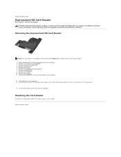
....dell.com/regulatory_compliance. Remove the battery. 6. Remove the keyboard. 11. Back to the computer. 12. Lift the clip that secures the hard-drive data cable to the system board and disconnect it from the computer. Remove the SD card, if applicable. 4. Remove the hard drive and audio board. 7. Remove the memory. 10. Remove the WLAN card. 8. Remove the screws that shipped with your computer. Remove the LCD cover. 9. Carefully turn over the computer. 13. Replacing the Card Reader...
....dell.com/regulatory_compliance. Remove the battery. 6. Remove the keyboard. 11. Back to the computer. 12. Lift the clip that secures the hard-drive data cable to the system board and disconnect it from the computer. Remove the SD card, if applicable. 4. Remove the hard drive and audio board. 7. Remove the memory. 10. Remove the WLAN card. 8. Remove the screws that shipped with your computer. Remove the LCD cover. 9. Carefully turn over the computer. 13. Replacing the Card Reader...
Service Manual
Page 18
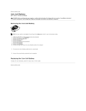
..., read the safety information that secures the coin-cell battery cable to the computer. 11. Back to Contents Page Coin-Cell Battery Dell™ Vostro™ V13 Service Manual WARNING: Before working inside your computer. Remove the hard drive and audio board. 7. Disconnect the coin-cell battery cable from the computer. Replacing the Coin-Cell Battery To replace the coin-cell battery, perform the above steps in reverse order. Remove the card reader. 10.
..., read the safety information that secures the coin-cell battery cable to the computer. 11. Back to Contents Page Coin-Cell Battery Dell™ Vostro™ V13 Service Manual WARNING: Before working inside your computer. Remove the hard drive and audio board. 7. Disconnect the coin-cell battery cable from the computer. Replacing the Coin-Cell Battery To replace the coin-cell battery, perform the above steps in reverse order. Remove the card reader. 10.
Service Manual
Page 25
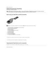
... Sink and Fan Assembly Dell™ Vostro™ V13 Service Manual WARNING: Before working inside your computer. Follow the procedures in reverse order. Remove the WLAN card. 8. Remove the memory. 10. Remove the keyboard. 11. For additional safety best practices information, see the Regulatory Compliance Homepage at www.dell.com/regulatory_compliance. Remove the SD card, if applicable. 4. Remove the hard drive and audio board. 7. Remove the coin-cell battery. 13. Remove the system board. 14. Back...
... Sink and Fan Assembly Dell™ Vostro™ V13 Service Manual WARNING: Before working inside your computer. Follow the procedures in reverse order. Remove the WLAN card. 8. Remove the memory. 10. Remove the keyboard. 11. For additional safety best practices information, see the Regulatory Compliance Homepage at www.dell.com/regulatory_compliance. Remove the SD card, if applicable. 4. Remove the hard drive and audio board. 7. Remove the coin-cell battery. 13. Remove the system board. 14. Back...

Service Manual
Page 27
... Display Panel NOTE: You may need to install Adobe® Flash® Player from the computer. Remove the base cover. 5. For additional safety best practices information, see the Regulatory Compliance Homepage at www.dell.com/regulatory_compliance. Back to Contents Page Display Panel Dell™ Vostro™ V13 Service Manual WARNING: Before working inside your computer. Remove the SD card, if applicable. 4. Remove the display panel from Adobe.com in order to the display cover...
... Display Panel NOTE: You may need to install Adobe® Flash® Player from the computer. Remove the base cover. 5. For additional safety best practices information, see the Regulatory Compliance Homepage at www.dell.com/regulatory_compliance. Back to Contents Page Display Panel Dell™ Vostro™ V13 Service Manual WARNING: Before working inside your computer. Remove the SD card, if applicable. 4. Remove the display panel from Adobe.com in order to the display cover...
Service Manual
Page 29
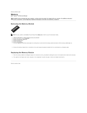
... apart the securing clips on the connector. 2. Remove the LCD cover. 7. Remove the ExpressCard, if applicable. 3. Use your computer. Follow the procedures in order to view the illustrations below. 1. Removing the Memory Module NOTE: You may need to install Adobe® Flash® Player from the system board at a 45-degree angle. Remove the SD card, if applicable. 4. Back to Contents Page Memory Dell™ Vostro™ V13 Service Manual WARNING: Before working...
... apart the securing clips on the connector. 2. Remove the LCD cover. 7. Remove the ExpressCard, if applicable. 3. Use your computer. Follow the procedures in order to view the illustrations below. 1. Removing the Memory Module NOTE: You may need to install Adobe® Flash® Player from the system board at a 45-degree angle. Remove the SD card, if applicable. 4. Back to Contents Page Memory Dell™ Vostro™ V13 Service Manual WARNING: Before working...
Service Manual
Page 30
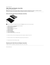
... base cover. 5. Remove the hard drive and audio board. 7. Release the antennae, camera, and display cables and remove them from the display assembly. Follow the procedures in reverse order. Remove the battery. 6. Remove the card reader. 12. Back to view the illustrations below. 1. Remove the SD card, if applicable. 4. Remove the coin-cell battery. 13. Remove the screws on the left of the display hinge. 15. Remove the LCD cover. 9. Replacing the Palm Rest and Display Assembly To replace...
... base cover. 5. Remove the hard drive and audio board. 7. Release the antennae, camera, and display cables and remove them from the display assembly. Follow the procedures in reverse order. Remove the battery. 6. Remove the card reader. 12. Back to view the illustrations below. 1. Remove the SD card, if applicable. 4. Remove the coin-cell battery. 13. Remove the screws on the left of the display hinge. 15. Remove the LCD cover. 9. Replacing the Palm Rest and Display Assembly To replace...
Service Manual
Page 37
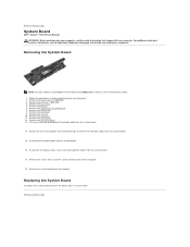
.... 4. Remove the hard drive and audio board. 7. Disconnect the display status sensor and touch-pad flex cables from Adobe.com in order to view the illustrations below. 1. Back to Contents Page System Board Dell™ Vostro™ V13 Service Manual WARNING: Before working inside your computer. Removing the System Board NOTE: You may need to release the antennae cables from the computer. Remove the base cover. 5. Remove the LCD cover. 9. Remove the coin-cell battery. 13. Remove the memory. 10. Remove...
.... 4. Remove the hard drive and audio board. 7. Disconnect the display status sensor and touch-pad flex cables from Adobe.com in order to view the illustrations below. 1. Back to Contents Page System Board Dell™ Vostro™ V13 Service Manual WARNING: Before working inside your computer. Removing the System Board NOTE: You may need to release the antennae cables from the computer. Remove the base cover. 5. Remove the LCD cover. 9. Remove the coin-cell battery. 13. Remove the memory. 10. Remove...
Service Manual
Page 39
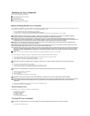
... as the metal at www.dell.com/regulatory_compliance. Open the display. 10. CAUTION: Before touching anything inside the computer. 1. Remove the hard drive (see Battery). 8. Damage due to prevent the computer cover from the computer. 5. CAUTION: Handle components and cards with locking tabs; As you service the computer. 7. Disconnect all network cables from being scratched. 2. Remove the main battery (see Hard Drive). CAUTION: Many repairs may require the following...
... as the metal at www.dell.com/regulatory_compliance. Open the display. 10. CAUTION: Before touching anything inside the computer. 1. Remove the hard drive (see Battery). 8. Damage due to prevent the computer cover from the computer. 5. CAUTION: Handle components and cards with locking tabs; As you service the computer. 7. Disconnect all network cables from being scratched. 2. Remove the main battery (see Hard Drive). CAUTION: Many repairs may require the following...


