Setup and Features Information Tech Sheet
Page 1
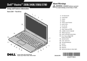
... (2) 2 camera light 3 camera 4 display 5 volume control buttons 6 power button 7 security slot 8 cooling vent 9 video connector (VGA) 10 e-SATA connector (shared) 11 USB 2.0 connector 12 power and battery status lights 13 5-in-1 Secure Digital (SD) memory card reader 14 wireless switch 15 audio connectors 16 touchpad buttons (2) 17 speaker 18 touchpad 19 keyboard 20 keyboard and device status lights Regulatory Model: P09S, P10G, P09F, P06E Regulatory Type: P09S001, P10G001, P09F001, P06E001 FILE LOCATION: C:\Documents and Settings\kandasamy_m\Desktop\Winery_A01\Info Dev Template Last Updated...
... (2) 2 camera light 3 camera 4 display 5 volume control buttons 6 power button 7 security slot 8 cooling vent 9 video connector (VGA) 10 e-SATA connector (shared) 11 USB 2.0 connector 12 power and battery status lights 13 5-in-1 Secure Digital (SD) memory card reader 14 wireless switch 15 audio connectors 16 touchpad buttons (2) 17 speaker 18 touchpad 19 keyboard 20 keyboard and device status lights Regulatory Model: P09S, P10G, P09F, P06E Regulatory Type: P09S001, P10G001, P09F001, P06E001 FILE LOCATION: C:\Documents and Settings\kandasamy_m\Desktop\Winery_A01\Info Dev Template Last Updated...
Setup and Features Information Tech Sheet
Page 3
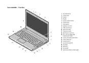
Vostro 3400/3500 - Front View 21 1 2 3 4 20 19 18 17 16 15 14 10 11 12 13 5 6 7 8 9 FILE LOCATION: C:\Documents and Settings\kandasamy_m\Desktop\Winery_A01\Info Dev 1 microphones (2) 2 camera light 3 camera 4 display 5 volume control buttons 6 power button 7 right speaker 8 network connector 9 USB 2.0 connector 10 optical drive/bay 11 fingerprint reader 12 ExpressCard connector 13 8-in-1 Secure Digital (SD) memory card reader 14 power and battery status lights 15 audio connectors 16 wireless switch 17 touchpad buttons (2) 18 touchpad 19 keyboard 20...
Vostro 3400/3500 - Front View 21 1 2 3 4 20 19 18 17 16 15 14 10 11 12 13 5 6 7 8 9 FILE LOCATION: C:\Documents and Settings\kandasamy_m\Desktop\Winery_A01\Info Dev 1 microphones (2) 2 camera light 3 camera 4 display 5 volume control buttons 6 power button 7 right speaker 8 network connector 9 USB 2.0 connector 10 optical drive/bay 11 fingerprint reader 12 ExpressCard connector 13 8-in-1 Secure Digital (SD) memory card reader 14 power and battery status lights 15 audio connectors 16 wireless switch 17 touchpad buttons (2) 18 touchpad 19 keyboard 20...
Setup and Features Information Tech Sheet
Page 5
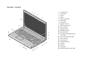
... 16 15 14 5 6 7 11 12 13 8 9 10 FILE LOCATION: C:\Documents and Settings\kandasamy_m\Desktop\Winery_A01\Info Dev 1 microphones (2) 2 camera light 3 camera 4 display 5 volume control lights 6 power button 7 right speaker 8 network connector 9 USB 2.0 connectors (2) 10 optical drive/bay 11 fingerprint reader 12 IEEE 1394 connector 13 ExpressCard slot 14 8-in-1 Secure Digital (SD) memory card reader 15 power and battery status lights 16 audio connectors 17 wireless switch 18 touchpad buttons (2) 19 touchpad 20 keyboard 21 left speaker 22 keyboard and device status lights Vostro 3700 -
... 16 15 14 5 6 7 11 12 13 8 9 10 FILE LOCATION: C:\Documents and Settings\kandasamy_m\Desktop\Winery_A01\Info Dev 1 microphones (2) 2 camera light 3 camera 4 display 5 volume control lights 6 power button 7 right speaker 8 network connector 9 USB 2.0 connectors (2) 10 optical drive/bay 11 fingerprint reader 12 IEEE 1394 connector 13 ExpressCard slot 14 8-in-1 Secure Digital (SD) memory card reader 15 power and battery status lights 16 audio connectors 17 wireless switch 18 touchpad buttons (2) 19 touchpad 20 keyboard 21 left speaker 22 keyboard and device status lights Vostro 3700 -
Setup and Features Information Tech Sheet
Page 7
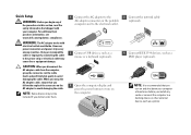
... not be included if you did not order them. 1 Connect the AC adapter to the AC adapter connector on the portable computer and to the electrical outlet. 3 Connect USB devices, such as a mouse or a keyboard (optional). 5 Open the computer display and press the power button to avoid damaging the cable. NOTE: Some devices may cause fire or equipment damage. Quick Setup WARNING: Before you begin any of the...
... not be included if you did not order them. 1 Connect the AC adapter to the AC adapter connector on the portable computer and to the electrical outlet. 3 Connect USB devices, such as a mouse or a keyboard (optional). 5 Open the computer display and press the power button to avoid damaging the cable. NOTE: Some devices may cause fire or equipment damage. Quick Setup WARNING: Before you begin any of the...

Service Manual
Page 1
...; If you make better use of Microsoft Corporation in the United States and/or other than its own. Dell™ Vostro™ 3700 Service Manual Working on Your Computer Specifications Removing and Replacing Parts System Setup Diagnostics Notes, Cautions, and Warnings NOTE: A NOTE indicates important information that helps you purchased a Dell™ n Series computer, any references in this document to Microsoft® Windows® operating systems are not...
...; If you make better use of Microsoft Corporation in the United States and/or other than its own. Dell™ Vostro™ 3700 Service Manual Working on Your Computer Specifications Removing and Replacing Parts System Setup Diagnostics Notes, Cautions, and Warnings NOTE: A NOTE indicates important information that helps you purchased a Dell™ n Series computer, any references in this document to Microsoft® Windows® operating systems are not...
Service Manual
Page 2
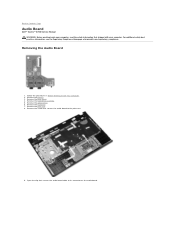
... practices information, see the Regulatory Compliance Homepage at www.dell.com/regulatory_compliance. Remove the base cover. 4. Removing the Audio Board 1. Remove the hard drive assembly. 5. Remove the keyboard. 7. Open the clip that secures the audio board to Contents Page Audio Board Dell™ Vostro™ 3700 Service Manual WARNING: Before working inside your computer, read the safety information that shipped with your computer. Back to the palm rest. 9. Remove the battery. 3. Remove the palm rest. 8.
... practices information, see the Regulatory Compliance Homepage at www.dell.com/regulatory_compliance. Remove the base cover. 4. Removing the Audio Board 1. Remove the hard drive assembly. 5. Remove the keyboard. 7. Open the clip that secures the audio board to Contents Page Audio Board Dell™ Vostro™ 3700 Service Manual WARNING: Before working inside your computer, read the safety information that shipped with your computer. Back to the palm rest. 9. Remove the battery. 3. Remove the palm rest. 8.

Service Manual
Page 9
.... 2. Select a menu to work incorrectly. Back to Contents Page System Setup Dell™ Vostro™ 3700 Service Manual Overview Entering System Setup System Setup Screens System Setup Options Overview Use System Setup as the user password l To read the current amount of memory or set the type of hard drive installed Before you use System Setup, it to display. Help - Save current configuration and exit System Setup. Certain changes can view information about your current settings. Options Field - and downarrow keys. CAUTION: Unless...
.... 2. Select a menu to work incorrectly. Back to Contents Page System Setup Dell™ Vostro™ 3700 Service Manual Overview Entering System Setup System Setup Screens System Setup Options Overview Use System Setup as the user password l To read the current amount of memory or set the type of hard drive installed Before you use System Setup, it to display. Help - Save current configuration and exit System Setup. Certain changes can view information about your current settings. Options Field - and downarrow keys. CAUTION: Unless...

Service Manual
Page 10
... video card. Enable or disable the external USB ports. Enable or disable the module bay. Main System Dell Bios Version Name System Date System Time Processor Type Processor Cores Processor ID Processor Speed Processor Minimum Clock Speed Processor Maximum Clock Speed L2 Cache Size L3 Cache Size System Memory Memory Speed Memory Channel Mode DIMM A Size DIMM B Size Internal HDD Fixed Bay Device Video Controller Video BIOS Version Video Memory Panel Type Native Resolution Audio Controller WWAN Bluetooth Device Wireless Device AC Adapter Type Displays the computer model number. Displays...
... video card. Enable or disable the external USB ports. Enable or disable the module bay. Main System Dell Bios Version Name System Date System Time Processor Type Processor Cores Processor ID Processor Speed Processor Minimum Clock Speed Processor Maximum Clock Speed L2 Cache Size L3 Cache Size System Memory Memory Speed Memory Channel Mode DIMM A Size DIMM B Size Internal HDD Fixed Bay Device Video Controller Video BIOS Version Video Memory Panel Type Native Resolution Audio Controller WWAN Bluetooth Device Wireless Device AC Adapter Type Displays the computer model number. Displays...

Service Manual
Page 11
... the hard drive is installed on self test (POST) which decreases the amount of time needed to boot the computer. EIST Execute Disable Bit Intel® Virtualization Technology Power Management USB Wake Support Wake On LAN Post Behavior Adapter Warnings Fast Boot Keyboard Click Wireless Internal Bluetooth Internal WLAN Internal WWAN Allows the clock speed of the processor to be remotely turned on. Default: Enabled Allows the computer to be dynamically changed by software...
... the hard drive is installed on self test (POST) which decreases the amount of time needed to boot the computer. EIST Execute Disable Bit Intel® Virtualization Technology Power Management USB Wake Support Wake On LAN Post Behavior Adapter Warnings Fast Boot Keyboard Click Wireless Internal Bluetooth Internal WLAN Internal WWAN Allows the clock speed of the processor to be remotely turned on. Default: Enabled Allows the computer to be dynamically changed by software...
Service Manual
Page 12
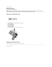
Remove the optical drive. 6. Remove the audio board. 9. Replacing the Bluetooth Card To replace the Bluetooth card, perform the above steps in Before Working Inside Your Computer. 2. Remove the battery. 3. Remove the hard drive. 5. Lift the Bluetooth® card up and away from the audio board. Follow the procedures in reverse order. Remove the palm rest. 8. Back to Contents Page Bluetooth Card Dell™ Vostro™ 3700 Service Manual WARNING: Before working inside your computer, read the safety information that shipped with...
Remove the optical drive. 6. Remove the audio board. 9. Replacing the Bluetooth Card To replace the Bluetooth card, perform the above steps in Before Working Inside Your Computer. 2. Remove the battery. 3. Remove the hard drive. 5. Lift the Bluetooth® card up and away from the audio board. Follow the procedures in reverse order. Remove the palm rest. 8. Back to Contents Page Bluetooth Card Dell™ Vostro™ 3700 Service Manual WARNING: Before working inside your computer, read the safety information that shipped with...
Service Manual
Page 13
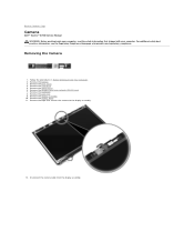
... the camera cable from the display assembly. Removing the Camera 1. Follow the procedures in Before Working Inside Your Computer. 2. Remove the keyboard. 8. Remove the display assembly. 10. Remove the wireless local area network (WLAN) card. 7. For additional safety best practices information, see the Regulatory Compliance Homepage at www.dell.com/regulatory_compliance. Remove the base cover. 4. Remove the optical drive. 6. Remove the tape that secures the camera to Contents Page Camera Dell™ Vostro™ 3700 Service Manual...
... the camera cable from the display assembly. Removing the Camera 1. Follow the procedures in Before Working Inside Your Computer. 2. Remove the keyboard. 8. Remove the display assembly. 10. Remove the wireless local area network (WLAN) card. 7. For additional safety best practices information, see the Regulatory Compliance Homepage at www.dell.com/regulatory_compliance. Remove the base cover. 4. Remove the optical drive. 6. Remove the tape that secures the camera to Contents Page Camera Dell™ Vostro™ 3700 Service Manual...
Service Manual
Page 17
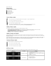
... board error 1. Turns on - l Light off only the Bluetooth wireless technology function, right-click the icon in a power management mode. For example, if four lights are installed Next Step 1. Turns on , the battery has 80 percent of its charge remaining. Appearance ON-FLASH-FLASH Description No SODIMMs are on when the Caps Lock function is enabled. Replace the system board. 3. Back to Contents Page Diagnostics Dell™ Vostro™ 3700 Service Manual Device Status Lights Battery Status Lights Battery Charge and Health Keyboard Status Lights LED Error Codes Device...
... board error 1. Turns on - l Light off only the Bluetooth wireless technology function, right-click the icon in a power management mode. For example, if four lights are installed Next Step 1. Turns on , the battery has 80 percent of its charge remaining. Appearance ON-FLASH-FLASH Description No SODIMMs are on when the Caps Lock function is enabled. Replace the system board. 3. Back to Contents Page Diagnostics Dell™ Vostro™ 3700 Service Manual Device Status Lights Battery Status Lights Battery Charge and Health Keyboard Status Lights LED Error Codes Device...

Service Manual
Page 18
... the hard drive and just the optical drive. 3. Try the other module in the same slot and test. Storage device error 1. Replace the system board. FLASH-ON-FLASH OFF-FLASH-OFF ON-FLASH-ON OFF-FLASH-FLASH FLASH-FLASH-FLASH FLASH-FLASH-OFF OFF-ON-OFF FLASH-FLASH-ON Back to Contents Page Display panel error 1. Reseat the display cable. 2. Replace the display panel. 3. Replace the video card/system board. Try the other module in the same slot and test. Replace the system board. Replace the system board. Option ROM error 1. Replace the system board.
... the hard drive and just the optical drive. 3. Try the other module in the same slot and test. Storage device error 1. Replace the system board. FLASH-ON-FLASH OFF-FLASH-OFF ON-FLASH-ON OFF-FLASH-FLASH FLASH-FLASH-FLASH FLASH-FLASH-OFF OFF-ON-OFF FLASH-FLASH-ON Back to Contents Page Display panel error 1. Reseat the display cable. 2. Replace the display panel. 3. Replace the video card/system board. Try the other module in the same slot and test. Replace the system board. Replace the system board. Option ROM error 1. Replace the system board.
Service Manual
Page 19
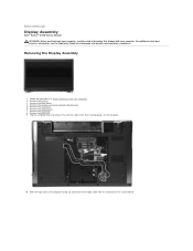
... Your Computer. 2. Remove the hard drive. 6. Remove the optical drive. 7. With the right side of the computer facing up, disconnect the display cable from their routing guides on the system board. For additional safety best practices information, see the Regulatory Compliance Homepage at www.dell.com/regulatory_compliance. Remove the base cover. 4. Back to Contents Page Display Assembly Dell™ Vostro™ 3700 Service Manual WARNING: Before working inside your...
... Your Computer. 2. Remove the hard drive. 6. Remove the optical drive. 7. With the right side of the computer facing up, disconnect the display cable from their routing guides on the system board. For additional safety best practices information, see the Regulatory Compliance Homepage at www.dell.com/regulatory_compliance. Remove the base cover. 4. Back to Contents Page Display Assembly Dell™ Vostro™ 3700 Service Manual WARNING: Before working inside your...
Service Manual
Page 31
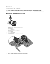
... cover. 4. Back to the system board. Disconnect the fan cable from its connector on the system board. 14. Remove the keyboard. 9. Removing the Heat Sink and Fan Assembly 1. Remove the coin-cell battery. 5. Loosen the screws that shipped with your computer, read the safety information that secure the heat sink and fan assembly to Contents Page Heat Sink and Fan Assembly Dell™ Vostro™ 3700 Service Manual...
... cover. 4. Back to the system board. Disconnect the fan cable from its connector on the system board. 14. Remove the keyboard. 9. Removing the Heat Sink and Fan Assembly 1. Remove the coin-cell battery. 5. Loosen the screws that shipped with your computer, read the safety information that secure the heat sink and fan assembly to Contents Page Heat Sink and Fan Assembly Dell™ Vostro™ 3700 Service Manual...

Service Manual
Page 33
... that secures the IO board to Contents Page IO Board Dell™ Vostro™ 3700 Service Manual WARNING: Before working inside your computer. Remove the palm rest. 10. Remove the wireless local area network (WLAN) card. 8. Lift the IO board and turn it over. Removing the IO Board 1. Remove the battery. 3. Remove the keyboard. 9. Remove the system board. 13. Remove the display assembly. 11. Remove the ExpressCard cage. 12. Remove the coin-cell battery. 5. Remove the hard drive. 6. For additional safety...
... that secures the IO board to Contents Page IO Board Dell™ Vostro™ 3700 Service Manual WARNING: Before working inside your computer. Remove the palm rest. 10. Remove the wireless local area network (WLAN) card. 8. Lift the IO board and turn it over. Removing the IO Board 1. Remove the battery. 3. Remove the keyboard. 9. Remove the system board. 13. Remove the display assembly. 11. Remove the ExpressCard cage. 12. Remove the coin-cell battery. 5. Remove the hard drive. 6. For additional safety...
Service Manual
Page 46
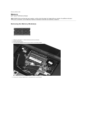
... board. Remove the battery. 3. Follow the procedures in Before Working Inside Your Computer. 2. For additional safety best practices information, see the Regulatory Compliance Homepage at www.dell.com/regulatory_compliance. Removing the Memory Module(s) 1. Push apart the memory retention clips to Contents Page Memory Dell™ Vostro™ 3700 Service Manual WARNING: Before working inside your computer, read the safety information that shipped with your computer. Remove the base cover...
... board. Remove the battery. 3. Follow the procedures in Before Working Inside Your Computer. 2. For additional safety best practices information, see the Regulatory Compliance Homepage at www.dell.com/regulatory_compliance. Removing the Memory Module(s) 1. Push apart the memory retention clips to Contents Page Memory Dell™ Vostro™ 3700 Service Manual WARNING: Before working inside your computer, read the safety information that shipped with your computer. Remove the base cover...

Service Manual
Page 69
... ExpressCard slot Cards supported 34 mm ExpressCards Ports and Connectors Audio Video IEEE 1394a Network adapter USB Memory card reader Mini-Card microphone connector, stereo headphone/speakers connector 15-pin VGA connector 19-pin HDMI connector one 4-pin connector RJ-45 connector four USB 2.0-compliant connector one eSATA/USB 2.0-compliant connector 8-in-1 memory card reader PCI-E half-mini card support for WLAN Drives Hard drive Optical drives Display Type Active area (X/Y) Dimensions Height Width Diagonal Maximum resolution Maximum brightness Operating angle...
... ExpressCard slot Cards supported 34 mm ExpressCards Ports and Connectors Audio Video IEEE 1394a Network adapter USB Memory card reader Mini-Card microphone connector, stereo headphone/speakers connector 15-pin VGA connector 19-pin HDMI connector one 4-pin connector RJ-45 connector four USB 2.0-compliant connector one eSATA/USB 2.0-compliant connector 8-in-1 memory card reader PCI-E half-mini card support for WLAN Drives Hard drive Optical drives Display Type Active area (X/Y) Dimensions Height Width Diagonal Maximum resolution Maximum brightness Operating angle...

Service Manual
Page 76
... main battery before you connect a cable, ensure that both connectors are disconnecting this document assumes that came with care. CAUTION: Before touching anything inside your computer and then unplug the cable from the computer. 5. Remove the hard drive (see Battery). 8. You should only perform troubleshooting and simple repairs as authorized in on the locking tabs before you turn the computer upside-down the operating...
... main battery before you connect a cable, ensure that both connectors are disconnecting this document assumes that came with care. CAUTION: Before touching anything inside your computer and then unplug the cable from the computer. 5. Remove the hard drive (see Battery). 8. You should only perform troubleshooting and simple repairs as authorized in on the locking tabs before you turn the computer upside-down the operating...

Service Manual
Page 77
... use only the battery designed for this particular Dell computer. Connect any external devices, such as a port replicator, battery slice, or media base, and replace any external devices, cards, and cables before turning on your computer. 3. The computer turns off when you connect any cards, such as shown below, and then click Shut Down. Connect any replacement procedure, ensure you shut down your operating system, press and hold the power button for other Dell...
... use only the battery designed for this particular Dell computer. Connect any external devices, such as a port replicator, battery slice, or media base, and replace any external devices, cards, and cables before turning on your computer. 3. The computer turns off when you connect any cards, such as shown below, and then click Shut Down. Connect any replacement procedure, ensure you shut down your operating system, press and hold the power button for other Dell...


