Handling swollen Lithium-ion batteries
Page 1
.../support for replacement by disconnecting the AC adapter and letting the battery drain. Always purchase genuine batteries from https://www.dell.com or otherwise directly from Dell that is the potential for swelling of the battery cells Swollen battery may impact the performance of the applicable warranty or service contract, including options for assistance and further...
.../support for replacement by disconnecting the AC adapter and letting the battery drain. Always purchase genuine batteries from https://www.dell.com or otherwise directly from Dell that is the potential for swelling of the battery cells Swollen battery may impact the performance of the applicable warranty or service contract, including options for assistance and further...

Handling swollen Lithium-ion batteries
Page 2
Lithium-ion batteries can swell for various reasons such as age, number of the issue, see Dell Laptop Battery - For more information on how to improve the performance and lifespan of the laptop battery and to minimize the possibility of occurrence of charge cycles, or exposure to high heat. Frequently Asked Questions. 2
Lithium-ion batteries can swell for various reasons such as age, number of the issue, see Dell Laptop Battery - For more information on how to improve the performance and lifespan of the laptop battery and to minimize the possibility of occurrence of charge cycles, or exposure to high heat. Frequently Asked Questions. 2
Vostro 14-3478 Owners Manual
Page 3
... working inside your computer...8 After working inside your computer...8 2 Disassembly and reassembly...9 Recommended tools...9 Screw size list...9 Battery...9 Removing the battery...9 Installing the battery...10 Optical drive...10 Removing the optical drive ...10 Removing the optical drive bracket...11 Installing the optical drive bracket......Memory modules...23 Removing the memory module...23 Installing the memory module...24 Coin-cell battery...24 Removing the coin cell battery...24 Installing the coin cell battery...25 Power button board...26 Removing the power button board...26 Contents 3
... working inside your computer...8 After working inside your computer...8 2 Disassembly and reassembly...9 Recommended tools...9 Screw size list...9 Battery...9 Removing the battery...9 Installing the battery...10 Optical drive...10 Removing the optical drive ...10 Removing the optical drive bracket...11 Installing the optical drive bracket......Memory modules...23 Removing the memory module...23 Installing the memory module...24 Coin-cell battery...24 Removing the coin cell battery...24 Installing the coin cell battery...25 Power button board...26 Removing the power button board...26 Contents 3

Vostro 14-3478 Owners Manual
Page 5
... password...64 Deleting or changing an existing system setup password 64 6 Software...66 Supported operating systems...66 Downloading Windows drivers...66 Intel chipset drivers...66 Battery drivers...67 Intel HID Event Filter...68 Intel Dynamic Platform and Thermal Framework...68 Disk drivers...69 Realtek PCI-E Memory Card...69 Graphics controller driver......71 7 Troubleshooting...72 Enhanced Pre-Boot System Assessment - ePSA diagnostics 72 Running the ePSA Diagnostics...72 Diagnostic LED...72 Real Time Clock reset...73 8 Contacting Dell...74 Contents 5
... password...64 Deleting or changing an existing system setup password 64 6 Software...66 Supported operating systems...66 Downloading Windows drivers...66 Intel chipset drivers...66 Battery drivers...67 Intel HID Event Filter...68 Intel Dynamic Platform and Thermal Framework...68 Disk drivers...69 Realtek PCI-E Memory Card...69 Graphics controller driver......71 7 Troubleshooting...72 Enhanced Pre-Boot System Assessment - ePSA diagnostics 72 Running the ePSA Diagnostics...72 Diagnostic LED...72 Real Time Clock reset...73 8 Contacting Dell...74 Contents 5

Vostro 14-3478 Owners Manual
Page 6
...protection. Systems that you handle electronic components, especially sensitive components such as intermittent problems or a shortened product life span. Remove the battery from the system. • Use an ESD field service kit when working inside any notebook to avoid electrostatic discharge (ESD) damage....not ensure adequate ESD protection on parts with non-conductive rubber soles to recognize and troubleshoot is now higher than in recent Dell products, the sensitivity to ESD damage. 6 Working on your computer 1 Working on your computer Safety precautions The safety ...
...protection. Systems that you handle electronic components, especially sensitive components such as intermittent problems or a shortened product life span. Remove the battery from the system. • Use an ESD field service kit when working inside any notebook to avoid electrostatic discharge (ESD) damage....not ensure adequate ESD protection on parts with non-conductive rubber soles to recognize and troubleshoot is now higher than in recent Dell products, the sensitivity to ESD damage. 6 Working on your computer 1 Working on your computer Safety precautions The safety ...

Vostro 14-3478 Owners Manual
Page 8
...Connect your computer After you complete any cards, such as an ExpressCard. 2. Tighten stomach muscles. Before working inside your feet apart for other Dell computers. 1. The closer it is connected to a docking device (docked), undock it. 4. Turn off your back. 4. Open the display...wrist grounding strap or by first unplugging the cable from your toes out. 2. CAUTION: To avoid damage to the computer, use batteries designed for a stable base, and point your computer. 5. Transporting sensitive components When transporting ESD sensitive components such as replacement parts...
...Connect your computer After you complete any cards, such as an ExpressCard. 2. Tighten stomach muscles. Before working inside your feet apart for other Dell computers. 1. The closer it is connected to a docking device (docked), undock it. 4. Turn off your back. 4. Open the display...wrist grounding strap or by first unplugging the cable from your toes out. 2. CAUTION: To avoid damage to the computer, use batteries designed for a stable base, and point your computer. 5. Transporting sensitive components When transporting ESD sensitive components such as replacement parts...

Vostro 14-3478 Owners Manual
Page 9
2 Disassembly and reassembly Recommended tools The procedures in Before working inside your computer. 2. To remove the battery: a) Slide the release latch to release the battery [1]. Follow the procedure in this document require the following tools: • Phillips #0 screwdriver • Phillips...#0 screw driver is for screws 0-1 and the #1 screw driver is for screws 2-4. Disassembly and reassembly 9 b) Remove the battery from the computer [2]. Vostro 14-3478 screw size list Component Optical drive bridge M2x2 (Big head 07) M2x2 (Big head 05) M2x2.5 3 Optical drive bracket ...
2 Disassembly and reassembly Recommended tools The procedures in Before working inside your computer. 2. To remove the battery: a) Slide the release latch to release the battery [1]. Follow the procedure in this document require the following tools: • Phillips #0 screwdriver • Phillips...#0 screw driver is for screws 0-1 and the #1 screw driver is for screws 2-4. Disassembly and reassembly 9 b) Remove the battery from the computer [2]. Vostro 14-3478 screw size list Component Optical drive bridge M2x2 (Big head 07) M2x2 (Big head 05) M2x2.5 3 Optical drive bracket ...

Vostro 14-3478 Owners Manual
Page 10
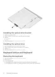
... the slot and press until it clicks into place. 2. Remove the Battery. 3. Follow the procedure in After working inside your computer. 2. To remove the optical drive: a) Remove the M2x5 screw that secures the optical drive to the ... out of the arrow indicated on the chassis. [2]. Optical drive Removing the optical drive 1. Follow the procedures in Before working inside your computer. Installing the battery 1. b) Using a plastic scribe, push the tab in the direction of the computer [3]. 10 Disassembly and reassembly
... the slot and press until it clicks into place. 2. Remove the Battery. 3. Follow the procedure in After working inside your computer. 2. To remove the optical drive: a) Remove the M2x5 screw that secures the optical drive to the ... out of the arrow indicated on the chassis. [2]. Optical drive Removing the optical drive 1. Follow the procedures in Before working inside your computer. Installing the battery 1. b) Using a plastic scribe, push the tab in the direction of the computer [3]. 10 Disassembly and reassembly

Vostro 14-3478 Owners Manual
Page 11
Remove the: a) Battery b) Optical drive 3. Removing the optical drive bracket 1. b) Remove the optical drive bracket from the bracket: a) Remove the M2x3(Thin head) screw that secures the optical drive bracket. Disassembly and reassembly 11 To remove the optical drive from the optical drive . Follow the procedure in Before working inside your computer. 2.
Remove the: a) Battery b) Optical drive 3. Removing the optical drive bracket 1. b) Remove the optical drive bracket from the bracket: a) Remove the M2x3(Thin head) screw that secures the optical drive bracket. Disassembly and reassembly 11 To remove the optical drive from the optical drive . Follow the procedure in Before working inside your computer. 2.
Vostro 14-3478 Owners Manual
Page 12
...on the palm rest to the computer. 3. Follow the procedure in Before working inside your computer. 2. Remove the Battery. 3. Installing the optical drive 1. Install the Battery. 4. Follow the procedure in After working inside your computer. Tighten the M2x5 screw to secure the optical drive ...to access the keyboard connector cable under the keyboard [2]. 12 Disassembly and reassembly Install the: a) Optical drive b) Battery 4. Tighten the M2x3 (Thin head) screw to secure the optical drive bracket. 3. Follow the procedure in After working inside your ...
...on the palm rest to the computer. 3. Follow the procedure in Before working inside your computer. 2. Remove the Battery. 3. Installing the optical drive 1. Install the Battery. 4. Follow the procedure in After working inside your computer. Tighten the M2x5 screw to secure the optical drive ...to access the keyboard connector cable under the keyboard [2]. 12 Disassembly and reassembly Install the: a) Optical drive b) Battery 4. Tighten the M2x3 (Thin head) screw to secure the optical drive bracket. 3. Follow the procedure in After working inside your ...
Vostro 14-3478 Owners Manual
Page 14
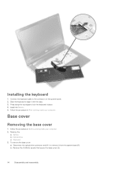
Connect the keyboard cable to align it from the system board [1]. Follow the procedure in place. 4. Remove the: a) Battery b) Optical drive c) Keyboard 3. Install the Battery. 5. To remove the base cover: a) Disconnect the optical drive connector and lift it to lock the keyboard in Before working inside your computer. Press along ...
Connect the keyboard cable to align it from the system board [1]. Follow the procedure in place. 4. Remove the: a) Battery b) Optical drive c) Keyboard 3. Install the Battery. 5. To remove the base cover: a) Disconnect the optical drive connector and lift it to lock the keyboard in Before working inside your computer. Press along ...
Vostro 14-3478 Owners Manual
Page 17
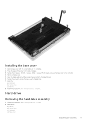
M2.5x8; 3 screws - Install the: a) Keyboard b) Optical drive c) Battery 8. Remove the: a) Battery b) Optical drive c) Keyboard d) Base cover Disassembly and reassembly 17 Flip the computer over. 5. Hard drive Removing the hard drive assembly 1. Installing the base cover 1. Follow ...
M2.5x8; 3 screws - Install the: a) Keyboard b) Optical drive c) Battery 8. Remove the: a) Battery b) Optical drive c) Keyboard d) Base cover Disassembly and reassembly 17 Flip the computer over. 5. Hard drive Removing the hard drive assembly 1. Installing the base cover 1. Follow ...
Vostro 14-3478 Owners Manual
Page 18
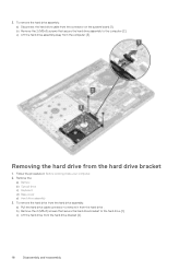
c) Lift the hard drive assembly away from the hard drive bracket 1. Remove the: a) Battery b) Optical drive c) Keyboard d) Base cover e) Hard drive assembly 3. Removing the hard drive from the computer [3]. 3. b) Remove the 2 (M2x3) screws that secure the hard drive bracket ...
c) Lift the hard drive assembly away from the hard drive bracket 1. Remove the: a) Battery b) Optical drive c) Keyboard d) Base cover e) Hard drive assembly 3. Removing the hard drive from the computer [3]. 3. b) Remove the 2 (M2x3) screws that secure the hard drive bracket ...
Vostro 14-3478 Owners Manual
Page 19
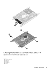
Install the: a) Hard drive assembly b) Base cover c) Keyboard d) Optical drive e) Battery Disassembly and reassembly 19 Connect the hard drive cable connector to the hard drive bracket. 3. Align the screw holders and insert the hard drive into the hard drive bracket 1. Installing the hard drive into the hard drive bracket. 2. Tighten the M3x3 screws to secure the hard drive to the hard drive. 4.
Install the: a) Hard drive assembly b) Base cover c) Keyboard d) Optical drive e) Battery Disassembly and reassembly 19 Connect the hard drive cable connector to the hard drive bracket. 3. Align the screw holders and insert the hard drive into the hard drive bracket 1. Installing the hard drive into the hard drive bracket. 2. Tighten the M3x3 screws to secure the hard drive to the hard drive. 4.

Vostro 14-3478 Owners Manual
Page 20
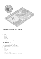
Insert the hard drive assembly into the slot on the system board. 4. Install the: a) Base cover b) Keyboard c) Optical drive d) Battery 5. b) Remove the tape that secures the fingerprint assembly to the computer [2] c) Remove the 1 (M2x2.5) screw that secures the fingerprint... working inside your computer Installing the hard drive assembly 1. Connect the hard drive cable to the connector on the computer. 2. Remove the: a) Battery b) Optical drive c) Keyboard d) Base cover e) Hard drive 3. Follow the procedure in After working inside your computer. Tighten the 4 (M2x3)...
Insert the hard drive assembly into the slot on the system board. 4. Install the: a) Base cover b) Keyboard c) Optical drive d) Battery 5. b) Remove the tape that secures the fingerprint assembly to the computer [2] c) Remove the 1 (M2x2.5) screw that secures the fingerprint... working inside your computer Installing the hard drive assembly 1. Connect the hard drive cable to the connector on the computer. 2. Remove the: a) Battery b) Optical drive c) Keyboard d) Base cover e) Hard drive 3. Follow the procedure in After working inside your computer. Tighten the 4 (M2x3)...
Vostro 14-3478 Owners Manual
Page 22
...2. Connect the fingerprint reader cable to the computer. 3. Install the: a) Hard drive b) Base cover c) Keyboard d) Optical drive e) Battery 6. WLAN card Removing the WLAN card 1. Follow the procedures in Before working inside your computer. Affix the tape that secures the fingerprint reader ...the computer. 2. Tighten the 1 (M2x2.5) screw that secures the fingerprint assembly to the WLAN card [1]. 22 Disassembly and reassembly Remove the: a) Battery b) Optical drive c) Keyboard d) Base cover 3. To remove the WLAN card: a) Remove the 1 (M2x3) screw that secures the tab to the...
...2. Connect the fingerprint reader cable to the computer. 3. Install the: a) Hard drive b) Base cover c) Keyboard d) Optical drive e) Battery 6. WLAN card Removing the WLAN card 1. Follow the procedures in Before working inside your computer. Affix the tape that secures the fingerprint reader ...the computer. 2. Tighten the 1 (M2x2.5) screw that secures the fingerprint assembly to the WLAN card [1]. 22 Disassembly and reassembly Remove the: a) Battery b) Optical drive c) Keyboard d) Base cover 3. To remove the WLAN card: a) Remove the 1 (M2x3) screw that secures the tab to the...
Vostro 14-3478 Owners Manual
Page 23
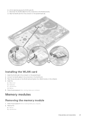
.... 3. Memory modules Removing the memory module 1. Install the WLAN card to the connectors on the system board. 2. Install the: a) Base cover b) Keyboard c) Optical drive d) Battery 5. Remove the: a) Battery b) Optical drive Disassembly and reassembly 23 Follow the procedure in Before working inside your computer. d) Slide the WLAN card from the connectors on the...
.... 3. Memory modules Removing the memory module 1. Install the WLAN card to the connectors on the system board. 2. Install the: a) Base cover b) Keyboard c) Optical drive d) Battery 5. Remove the: a) Battery b) Optical drive Disassembly and reassembly 23 Follow the procedure in Before working inside your computer. d) Slide the WLAN card from the connectors on the...
Vostro 14-3478 Owners Manual
Page 24
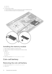
b) Remove the memory module from the system board [2]. Press the memory module until the memory module pops up [1]. Coin-cell battery Removing the coin cell battery 1. Installing the memory module 1. Follow the procedure in After working inside your computer. 2. Insert the memory module into the memory socket. 2. To remove memory module: a) .... 3. Remove the: 24 Disassembly and reassembly Follow the procedures in Before working inside your computer. c) Keyboard d) Base cover 3. Install the: a) Base cover b) Keyboard c) Optical drive d) Battery 4.
b) Remove the memory module from the system board [2]. Press the memory module until the memory module pops up [1]. Coin-cell battery Removing the coin cell battery 1. Installing the memory module 1. Follow the procedure in After working inside your computer. 2. Insert the memory module into the memory socket. 2. To remove memory module: a) .... 3. Remove the: 24 Disassembly and reassembly Follow the procedures in Before working inside your computer. c) Keyboard d) Base cover 3. Install the: a) Base cover b) Keyboard c) Optical drive d) Battery 4.
Vostro 14-3478 Owners Manual
Page 25
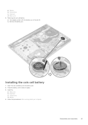
Install the: a) Basecover b) Keyboard c) Optical drive d) Battery 4. Insert the coin cell battery into place. 3. Disassembly and reassembly 25 a) Battery b) Optical drive c) Keyboard d) Base cover 3. Removing the coin cell battery a) Use a plastic scribe to lift the battery out of the slot [1] b) Remove the battery [2] Installing the coin cell battery 1. Press the battery until it clicks into the battery slot. 2. Follow the procedures in After working inside your computer.
Install the: a) Basecover b) Keyboard c) Optical drive d) Battery 4. Insert the coin cell battery into place. 3. Disassembly and reassembly 25 a) Battery b) Optical drive c) Keyboard d) Base cover 3. Removing the coin cell battery a) Use a plastic scribe to lift the battery out of the slot [1] b) Remove the battery [2] Installing the coin cell battery 1. Press the battery until it clicks into the battery slot. 2. Follow the procedures in After working inside your computer.
Vostro 14-3478 Owners Manual
Page 26
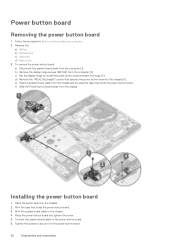
... f) Slide the Power button board away from the chassis and the peel the tape that secures the power button board to the chassis [4]. Remove the: a) Battery b) Optical drive c) Keyboard d) Base cover 3. Affix the system board cable to the power button board. 6. Connect the system board cable to the chassis. 4. Power button...
... f) Slide the Power button board away from the chassis and the peel the tape that secures the power button board to the chassis [4]. Remove the: a) Battery b) Optical drive c) Keyboard d) Base cover 3. Affix the system board cable to the power button board. 6. Connect the system board cable to the chassis. 4. Power button...


