
User Manual
Page 1
... status light 2. USB 2.0 connectors (2) 6. optical drive 7. touchpad buttons (2) 13. power button Regulatory Model: P22G,P18F Regulatory Type: P22G004, P18F004 2012 - 02 microphone 10. Vostro 2420 - camera 3. Dell Vostro 2420/2520 Setup And Features Information About Warnings WARNING: A WARNING indicates a potential for property damage, personal injury, or death. speakers (2) 5. optical drive eject button 8. audio connectors...
... status light 2. USB 2.0 connectors (2) 6. optical drive 7. touchpad buttons (2) 13. power button Regulatory Model: P22G,P18F Regulatory Type: P22G004, P18F004 2012 - 02 microphone 10. Vostro 2420 - camera 3. Dell Vostro 2420/2520 Setup And Features Information About Warnings WARNING: A WARNING indicates a potential for property damage, personal injury, or death. speakers (2) 5. optical drive eject button 8. audio connectors...

User Manual
Page 3
camera 3. optical drive 6. optical drive eject button 7. microphone 11. Vostro 2520 - memory card reader 12. device status lights 13. speakers (2) 5. Front View 1. keyboard 14. touchpad buttons (2) 10. camera status light 2. display 4. USB 2.0 connectors (2) 8. touchpad 9. power button 3 Front And Back View Figure 3.
camera 3. optical drive 6. optical drive eject button 7. microphone 11. Vostro 2520 - memory card reader 12. device status lights 13. speakers (2) 5. Front View 1. keyboard 14. touchpad buttons (2) 10. camera status light 2. display 4. USB 2.0 connectors (2) 8. touchpad 9. power button 3 Front And Back View Figure 3.
Owner's Manual
Page 3
... Hinge Cover...11 Removing the Keyboard...11 Installing the Keyboard...13 Removing the Optical Drive...13 Installing the Optical Drive...14 Removing the Memory Module...14 Installing the Memory Module...15 Removing the Palmrest...15 Installing the Palmrest...16 Removing the Power-Button Board...17 Installing the Power-Button Board...18 Removing...
... Hinge Cover...11 Removing the Keyboard...11 Installing the Keyboard...13 Removing the Optical Drive...13 Installing the Optical Drive...14 Removing the Memory Module...14 Installing the Memory Module...15 Removing the Palmrest...15 Installing the Palmrest...16 Removing the Power-Button Board...17 Installing the Power-Button Board...18 Removing...
Owner's Manual
Page 10
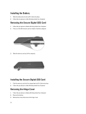
... into place. 2. Remove the screw that secures the hinge cover. 10 Removing the Secure Digital (SD) Card 1. Push the memory card into place. 2. Slide the memory card out of the computer. Press in on the SD memory card to release it clicks into the compartment until it from the computer. 3. Remove the battery. 3.
... into place. 2. Remove the screw that secures the hinge cover. 10 Removing the Secure Digital (SD) Card 1. Push the memory card into place. 2. Slide the memory card out of the computer. Press in on the SD memory card to release it clicks into the compartment until it from the computer. 3. Remove the battery. 3.
Owner's Manual
Page 14
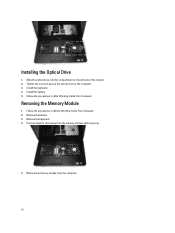
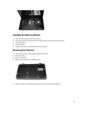
Remove the keyboard. 4. Install the keyboard. 4. Follow the procedures in Before Working Inside Your Computer. 2. Follow the procedures in After Working Inside Your Computer. Tighten the screw to secure the optical drive to the computer. 3. Removing the Memory Module 1. Install the battery. 5. Installing the Optical Drive 1. Slide the optical drive into the compartment on the left side of the chassis. 2. Remove the memory module from the memory module until it pops up. 5. Remove the battery. 3. Pry the retention clips away from the computer. 14
Remove the keyboard. 4. Install the keyboard. 4. Follow the procedures in Before Working Inside Your Computer. 2. Follow the procedures in After Working Inside Your Computer. Tighten the screw to secure the optical drive to the computer. 3. Removing the Memory Module 1. Install the battery. 5. Installing the Optical Drive 1. Slide the optical drive into the compartment on the left side of the chassis. 2. Remove the memory module from the memory module until it pops up. 5. Remove the battery. 3. Pry the retention clips away from the computer. 14
Owner's Manual
Page 15
Removing the Palmrest 1. Install the keyboard. 4. Follow the procedures in place. 3. Remove the keyboard. 4. Press down on the memory module until the retention clips secure the memory module in After Working Inside Your Computer. Flip the computer and disconnect the power board cable (1) and the touchpad cable (2). 15 Install the battery. 5. Installing the Memory Module 1. Follow the procedures in Before Working Inside Your Computer. 2. Remove the battery. 3. Remove the screws that secure the bottom base. 5. Insert the memory module into the memory socket. 2.
Removing the Palmrest 1. Install the keyboard. 4. Follow the procedures in place. 3. Remove the keyboard. 4. Press down on the memory module until the retention clips secure the memory module in After Working Inside Your Computer. Flip the computer and disconnect the power board cable (1) and the touchpad cable (2). 15 Install the battery. 5. Installing the Memory Module 1. Follow the procedures in Before Working Inside Your Computer. 2. Remove the battery. 3. Remove the screws that secure the bottom base. 5. Insert the memory module into the memory socket. 2.
Owner's Manual
Page 26
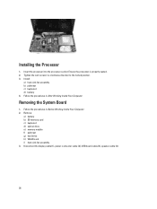
... Tighten the cam-screw in After Working Inside Your Computer. Follow the procedures in a clockwise direction to the locked position. 3. Remove: a) battery b) SD memory card c) keyboard d) optical drive e) memory module f) palmrest g) hard drive h) WLAN card i) heat-sink fan assembly 3. Insert the processor into the processor socket. Follow the procedures in Before Working...
... Tighten the cam-screw in After Working Inside Your Computer. Follow the procedures in a clockwise direction to the locked position. 3. Remove: a) battery b) SD memory card c) keyboard d) optical drive e) memory module f) palmrest g) hard drive h) WLAN card i) heat-sink fan assembly 3. Insert the processor into the processor socket. Follow the procedures in Before Working...
Owner's Manual
Page 28
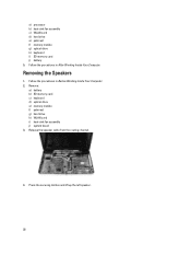
Follow the procedures in Before Working Inside Your Computer. 2. Release the speaker cable from the routing channel. 4. Removing the Speakers 1. Remove: a) battery b) SD memory card c) keyboard d) optical drive e) memory module f) palmrest g) hard drive h) WLAN card i) heat-sink fan assembly j) system board 3. Press the securing latches and lift up the left speaker. 28 a) processor...
Follow the procedures in Before Working Inside Your Computer. 2. Release the speaker cable from the routing channel. 4. Removing the Speakers 1. Remove: a) battery b) SD memory card c) keyboard d) optical drive e) memory module f) palmrest g) hard drive h) WLAN card i) heat-sink fan assembly j) system board 3. Press the securing latches and lift up the left speaker. 28 a) processor...
Owner's Manual
Page 30
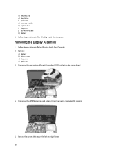
Removing the Display Assembly 1. Remove the screws that secure the left and right hinges. 30 d) WLAN card e) hard drive f) palmrest g) memory module h) optical drive i) keyboard j) SD memory card k) battery 4. Follow the procedures in Before Working Inside Your Computer. 2. Follow the procedures in After Working Inside Your Computer. Disconnect the WLAN antennae and release it from the system board. 4. Remove: a) battery b) hinge cover c) keyboard d) palmrest 3. Disconnect the low-voltage differential signaling (LVDS) cable from the routing channel on the chassis. 5.
Removing the Display Assembly 1. Remove the screws that secure the left and right hinges. 30 d) WLAN card e) hard drive f) palmrest g) memory module h) optical drive i) keyboard j) SD memory card k) battery 4. Follow the procedures in Before Working Inside Your Computer. 2. Follow the procedures in After Working Inside Your Computer. Disconnect the WLAN antennae and release it from the system board. 4. Remove: a) battery b) hinge cover c) keyboard d) palmrest 3. Disconnect the low-voltage differential signaling (LVDS) cable from the routing channel on the chassis. 5.

Owner's Manual
Page 42
...collapses a drop‐down list, if applicable. Re-sets the date on the computer. Displays the service tag of the processor. Displays the memory installed on the computer's internal calendar. System Setup Options Main System Information System Date System Time BIOS Version Product Name Service Tag Asset Tag CPU... Type CPU Speed CPU ID L1 Cache Size L2 Cache Size L3 Cache Size Extended Memory System Memory Memory Speed Fixed HDD SATA ODD AC Adapter Type Displays the computer model number. Displays the BIOS revision. Re-sets the time on the...
...collapses a drop‐down list, if applicable. Re-sets the date on the computer. Displays the service tag of the processor. Displays the memory installed on the computer's internal calendar. System Setup Options Main System Information System Date System Time BIOS Version Product Name Service Tag Asset Tag CPU... Type CPU Speed CPU ID L1 Cache Size L2 Cache Size L3 Cache Size Extended Memory System Memory Memory Speed Fixed HDD SATA ODD AC Adapter Type Displays the computer model number. Displays the BIOS revision. Re-sets the time on the...
Owner's Manual
Page 48
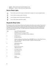
... and blinks when the computer is in progress or failure System board failure, covers BIOS corruption or ROM error 2 No RAM detected No memory detected 3 Chipset Error (North and South Bridge Chipset, DMA/IMR/ Timer Error) , Time-Of-Day Clock test failure , Gate A20... failure , Super I/O chip failure , Keyboard controller test failure System board failure 4 RAM Read/Write failure Memory failure 5 Real-time clock power fail CMOS battery failure 6 Video BIOS test failure Video card failure 7 Processor failure Processor failure 8 Display ...
... and blinks when the computer is in progress or failure System board failure, covers BIOS corruption or ROM error 2 No RAM detected No memory detected 3 Chipset Error (North and South Bridge Chipset, DMA/IMR/ Timer Error) , Time-Of-Day Clock test failure , Gate A20... failure , Super I/O chip failure , Keyboard controller test failure System board failure 4 RAM Read/Write failure Memory failure 5 Real-time clock power fail CMOS battery failure 6 Video BIOS test failure Video card failure 7 Processor failure Processor failure 8 Display ...
Owner's Manual
Page 49
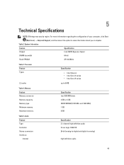
Memory Feature Memory connector Memory capacity Memory type Minimum memory Maximum memory Specification two SODIMM slots 2 GB or 4 GB DDR3 SDRAM (1333 MHz and 1600 MHz) 1 GB 8 GB Table 5. System Information Feature Specification Chipset Intel HM75 Express ...
Memory Feature Memory connector Memory capacity Memory type Minimum memory Maximum memory Specification two SODIMM slots 2 GB or 4 GB DDR3 SDRAM (1333 MHz and 1600 MHz) 1 GB 8 GB Table 5. System Information Feature Specification Chipset Intel HM75 Express ...


