
Setup and Features Information Tech Sheet
Page 6
...: Before you begin any of the procedures in the air vents. Fan noise is running. For additional best practices information see www.dell.com/regulatory_compliance. WARNING: The AC adapter works with your Dell™ computer in a low-airflow environment, such as a closed ...briefcase, while it is normal and does not indicate a problem with the fan or the computer. 9 8 7 4 5 6 1 2 3 ...
...: Before you begin any of the procedures in the air vents. Fan noise is running. For additional best practices information see www.dell.com/regulatory_compliance. WARNING: The AC adapter works with your Dell™ computer in a low-airflow environment, such as a closed ...briefcase, while it is normal and does not indicate a problem with the fan or the computer. 9 8 7 4 5 6 1 2 3 ...
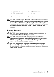
Setup and Quick Reference Guide
Page 9
... in this section, follow the safety instructions that shipped with your computer. About Your Computer 9 The computer turns on the fan when the computer gets hot. CAUTION: Before removing or replacing the battery, turn off the computer, disconnect the AC adapter ... any of fire or explosion. Restricting the airflow can damage the computer or cause a fire. Do not use a battery from other external cables from Dell. Fan noise is running. 1 wireless switch 3 USB connectors (2) 5 AC Adapter connector 7 video connector 2 ExpressCard/54 slot 4 air vents 6 network connector...
... in this section, follow the safety instructions that shipped with your computer. About Your Computer 9 The computer turns on the fan when the computer gets hot. CAUTION: Before removing or replacing the battery, turn off the computer, disconnect the AC adapter ... any of fire or explosion. Restricting the airflow can damage the computer or cause a fire. Do not use a battery from other external cables from Dell. Fan noise is running. 1 wireless switch 3 USB connectors (2) 5 AC Adapter connector 7 video connector 2 ExpressCard/54 slot 4 air vents 6 network connector...
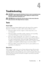
Setup and Quick Reference Guide
Page 31
... shipped with your computer from the electrical outlet before opening the cover. Troubleshooting CAUTION: To guard against the likelihood of electric shock, laceration by moving fan blades, or other expected injuries, always unplug your computer. One possible beep code consists of repetitive three short beeps.
... shipped with your computer from the electrical outlet before opening the cover. Troubleshooting CAUTION: To guard against the likelihood of electric shock, laceration by moving fan blades, or other expected injuries, always unplug your computer. One possible beep code consists of repetitive three short beeps.
Service Manual
Page 1
...trademarks or registered trademarks of Microsoft Corporation in this text: Dell, the DELL logo, and Vostro are not applicable. Bluetooth is a registered trademark of your computer. A00 Dell™ Vostro™ 2510 Service Manual Troubleshooting Before Working on Your Computer Hard Drive ...Wireless Local Area Network (WLAN) Card Fan Processor Heat Sink Processor Module Memory Hinge Cover Keyboard Display...
...trademarks or registered trademarks of Microsoft Corporation in this text: Dell, the DELL logo, and Vostro are not applicable. Bluetooth is a registered trademark of your computer. A00 Dell™ Vostro™ 2510 Service Manual Troubleshooting Before Working on Your Computer Hard Drive ...Wireless Local Area Network (WLAN) Card Fan Processor Heat Sink Processor Module Memory Hinge Cover Keyboard Display...
Service Manual
Page 13
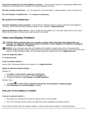
...headphone connector. Adjust the Windows display settings - Click Start Control Panel Appearance and Themes. 2. Contact Dell Support. Run the Hardware Troubleshooter - Try different settings for troubleshooting purposes. Ensure that the sound is securely inserted ...Resolution and Colors settings, as needed. Turn off nearby fans, fluorescent lights, or halogen lamps to the computer. 2. For information about your computer at www.dell.com/regulatory_compliance. If you want to support.dell.com. Windows Vista: 1. Disconnect headphones from the headphone...
...headphone connector. Adjust the Windows display settings - Click Start Control Panel Appearance and Themes. 2. Contact Dell Support. Run the Hardware Troubleshooter - Try different settings for troubleshooting purposes. Ensure that the sound is securely inserted ...Resolution and Colors settings, as needed. Turn off nearby fans, fluorescent lights, or halogen lamps to the computer. 2. For information about your computer at www.dell.com/regulatory_compliance. If you want to support.dell.com. Windows Vista: 1. Disconnect headphones from the headphone...
Service Manual
Page 24
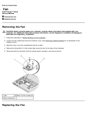
... three M2.5 x 5-mm screws that secure the fan to Contents Page Fan Dell™ Vostro™ 2510 Service Manual Removing the Fan Replacing the Fan Removing the Fan CAUTION: Before working inside your computer. Disconnect the fan connector from the system board connector, and remove the fan. 1 fan 2 M2.5 x 5-mm screws (3) 3 fan connector Replacing the Fan For additional safety best practices information, see...
... three M2.5 x 5-mm screws that secure the fan to Contents Page Fan Dell™ Vostro™ 2510 Service Manual Removing the Fan Replacing the Fan Removing the Fan CAUTION: Before working inside your computer. Disconnect the fan connector from the system board connector, and remove the fan. 1 fan 2 M2.5 x 5-mm screws (3) 3 fan connector Replacing the Fan For additional safety best practices information, see...

Service Manual
Page 25
... your computer, read the safety information that you have completed the removal procedure Removing the Fan. 1. For additional safety best practices information, see the Regulatory Compliance Homepage at www.dell.com/regulatory_compliance. This procedure assumes that shipped with the holes on the base of the ...computer. 3. Replace the three M2.5 x 5-mm screws to secure the fan to the base of the computer. 2. Back to ...
... your computer, read the safety information that you have completed the removal procedure Removing the Fan. 1. For additional safety best practices information, see the Regulatory Compliance Homepage at www.dell.com/regulatory_compliance. This procedure assumes that shipped with the holes on the base of the ...computer. 3. Replace the three M2.5 x 5-mm screws to secure the fan to the base of the computer. 2. Back to ...
Service Manual
Page 26
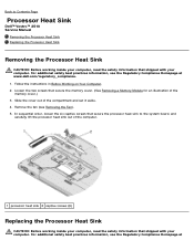
... In sequential order, loosen the six captive screws that secure the processor heat sink to Contents Page Processor Heat Sink Dell™ Vostro™ 2510 Service Manual Removing the Processor Heat Sink Replacing the Processor Heat Sink Removing the Processor Heat Sink CAUTION: Before working ... with your computer. For additional safety best practices information, see the Regulatory Compliance Homepage at www.dell.com/regulatory_compliance. 1. For additional safety best practices information, see Removing the Fan). 5. Remove the fan (see the Regulatory Compliance Homepage at
... In sequential order, loosen the six captive screws that secure the processor heat sink to Contents Page Processor Heat Sink Dell™ Vostro™ 2510 Service Manual Removing the Processor Heat Sink Replacing the Processor Heat Sink Removing the Processor Heat Sink CAUTION: Before working ... with your computer. For additional safety best practices information, see the Regulatory Compliance Homepage at www.dell.com/regulatory_compliance. 1. For additional safety best practices information, see Removing the Fan). 5. Remove the fan (see the Regulatory Compliance Homepage at

Service Manual
Page 27
Replace the memory cover and tighten the screws. Back to Contents Page www.dell.com/regulatory_compliance. Align the six captive screws on the processor heat sink with the screw holes on the system board and tighten the screws in sequential order. 2. This procedure assumes that you have completed the removal procedure Removing the Processor Heat Sink. 1. Replace the fan (see Replacing the Fan). 3.
Replace the memory cover and tighten the screws. Back to Contents Page www.dell.com/regulatory_compliance. Align the six captive screws on the processor heat sink with the screw holes on the system board and tighten the screws in sequential order. 2. This procedure assumes that you have completed the removal procedure Removing the Processor Heat Sink. 1. Replace the fan (see Replacing the Fan). 3.
Service Manual
Page 28
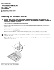
...thermal-cooling assembly (see Removing the Fan). 5. To loosen the ZIF socket, use a small, flat-blade screwdriver and rotate the ZIF-socket cam screw counterclockwise until it comes to Contents Page Processor Module Dell™ Vostro™ 2510 Service Manual Removing the Processor Module Replacing...Assembly). Loosen the two screws that it aside. 4. For additional safety best practices information, see the Regulatory Compliance Homepage at www.dell.com/regulatory_compliance. 1. NOTICE: To avoid damage to the processor, hold the screwdriver so that secure the memory cover. (See ...
...thermal-cooling assembly (see Removing the Fan). 5. To loosen the ZIF socket, use a small, flat-blade screwdriver and rotate the ZIF-socket cam screw counterclockwise until it comes to Contents Page Processor Module Dell™ Vostro™ 2510 Service Manual Removing the Processor Module Replacing...Assembly). Loosen the two screws that it aside. 4. For additional safety best practices information, see the Regulatory Compliance Homepage at www.dell.com/regulatory_compliance. 1. NOTICE: To avoid damage to the processor, hold the screwdriver so that secure the memory cover. (See ...

Service Manual
Page 30
Replace the fan (see Replacing the Processor Thermal-Cooling Assembly). 4. turning the cam screw. 2. Back to the system board. 3. Replace the memory cover and tighten the screws. Tighten the ZIF socket by turning the cam screw clockwise to secure the processor module to Contents Page Replace the processor thermal-cooling assembly (see Replacing the Fan). 5.
Replace the fan (see Replacing the Processor Thermal-Cooling Assembly). 4. turning the cam screw. 2. Back to the system board. 3. Replace the memory cover and tighten the screws. Tighten the ZIF socket by turning the cam screw clockwise to secure the processor module to Contents Page Replace the processor thermal-cooling assembly (see Replacing the Fan). 5.
Service Manual
Page 49
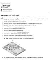
... top of the palm rest. Follow the instructions in - 1 card slot. 4. Remove the keyboard (see the Regulatory Compliance Homepage at www.dell.com/regulatory_compliance. 1. Remove the hard drive cover. NOTE: The screw locations may vary slightly from the bottom of the hard drive cover. 3.....5 x 5-mm screws that shipped with a "P" from the fan. 9. Remove the WLAN card (see Removing the Hinge Cover). 6. Remove the hinge cover (see Removing a WLAN Card). 5. Back to Contents Page Palm Rest Dell™ Vostro™ 2510 Service Manual Removing the Palm Rest Replacing the Palm Rest Removing...
... top of the palm rest. Follow the instructions in - 1 card slot. 4. Remove the keyboard (see the Regulatory Compliance Homepage at www.dell.com/regulatory_compliance. 1. Remove the hard drive cover. NOTE: The screw locations may vary slightly from the bottom of the hard drive cover. 3.....5 x 5-mm screws that shipped with a "P" from the fan. 9. Remove the WLAN card (see Removing the Hinge Cover). 6. Remove the hinge cover (see Removing a WLAN Card). 5. Back to Contents Page Palm Rest Dell™ Vostro™ 2510 Service Manual Removing the Palm Rest Replacing the Palm Rest Removing...
Service Manual
Page 51
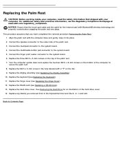
...the three M2.5 x 5-mm screws on the bottom of the palm rest. 3. Replace the WLAN card (see the Regulatory Compliance Homepage at www.dell.com/regulatory_compliance. Replacing the Palm Rest CAUTION: Before working inside your computer. Replace the M2.5 x 5-mm screw in the hole labeled with your... computer, read the safety information that shipped with a "P" on the fan. 9. Connect the finger print reader connector to the under side of the computer to the system board. 5. NOTICE: Ensure that you removed from...
...the three M2.5 x 5-mm screws on the bottom of the palm rest. 3. Replace the WLAN card (see the Regulatory Compliance Homepage at www.dell.com/regulatory_compliance. Replacing the Palm Rest CAUTION: Before working inside your computer. Replace the M2.5 x 5-mm screw in the hole labeled with your... computer, read the safety information that shipped with a "P" on the fan. 9. Connect the finger print reader connector to the under side of the computer to the system board. 5. NOTICE: Ensure that you removed from...
Service Manual
Page 58
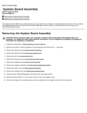
... the Palm Rest). 10. Remove the palm rest (see Removing the Fan). 6. For additional safety best practices information, see Removing the Keyboard). 8. Remove the keyboard (see the Regulatory Compliance Homepage at www.dell.com/regulatory_compliance. 1. Remove the optical drive (see Removing the Hinge Cover...of the system board. 13. The replacement kit for transferring the Service Tag to Contents Page System Board Assembly Dell™ Vostro™ 2510 Service Manual Removing the System Board Assembly Replacing the System Board Assembly The system board's BIOS chip contains the...
... the Palm Rest). 10. Remove the palm rest (see Removing the Fan). 6. For additional safety best practices information, see Removing the Keyboard). 8. Remove the keyboard (see the Regulatory Compliance Homepage at www.dell.com/regulatory_compliance. 1. Remove the optical drive (see Removing the Hinge Cover...of the system board. 13. The replacement kit for transferring the Service Tag to Contents Page System Board Assembly Dell™ Vostro™ 2510 Service Manual Removing the System Board Assembly Replacing the System Board Assembly The system board's BIOS chip contains the...
Service Manual
Page 59
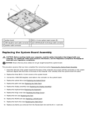
.... Replace the three M2.5 x 5-mm screws on the system board. 4. Replace the fan (see Replacing the Hinge Cover). 9. Insert the left side of the system board into the base of the computer, then carefully lower the system board ... the system board are aligned with your computer, read the safety information that shipped with the holes on the base of the computer at www.dell.com/regulatory_compliance. For additional safety best practices information, see Replacing the Hard Drive). 12. Connect the 1394/USB daughter-card cable to the connector on...
.... Replace the three M2.5 x 5-mm screws on the system board. 4. Replace the fan (see Replacing the Hinge Cover). 9. Insert the left side of the system board into the base of the computer, then carefully lower the system board ... the system board are aligned with your computer, read the safety information that shipped with the holes on the base of the computer at www.dell.com/regulatory_compliance. For additional safety best practices information, see Replacing the Hard Drive). 12. Connect the 1394/USB daughter-card cable to the connector on...
Service Manual
Page 66
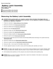
...the Hinge Cover). 6. Remove the hinge cover (see Removing the Fan). 5. For additional safety best practices information, see Removing a WLAN Card). 4. Remove the WLAN card (see the Regulatory Compliance Homepage at www.dell.com/regulatory_compliance. 1. Remove the display assembly (see Removing the ...spring. Remove the hard drive (see Removing the Hard Drive). 3. Back to Contents Page Battery Latch Assembly Dell™ Vostro™ 2510 Service Manual Removing the Battery Latch Assembly Replacing the Battery Latch Assembly Removing the Battery Latch Assembly CAUTION: Before ...
...the Hinge Cover). 6. Remove the hinge cover (see Removing the Fan). 5. For additional safety best practices information, see Removing a WLAN Card). 4. Remove the WLAN card (see the Regulatory Compliance Homepage at www.dell.com/regulatory_compliance. 1. Remove the display assembly (see Removing the ...spring. Remove the hard drive (see Removing the Hard Drive). 3. Back to Contents Page Battery Latch Assembly Dell™ Vostro™ 2510 Service Manual Removing the Battery Latch Assembly Replacing the Battery Latch Assembly Removing the Battery Latch Assembly CAUTION: Before ...

Service Manual
Page 68
Back to Contents Page Replace the WLAN card (see Replacing the Hinge Cover). 12. Replace the hinge cover (see Replacing a WLAN Card). Replace the hard drive (see Replacing the Fan). 13. 11. Replace the fan (see Replacing the Hard Drive). 14.
Back to Contents Page Replace the WLAN card (see Replacing the Hinge Cover). 12. Replace the hinge cover (see Replacing a WLAN Card). Replace the hard drive (see Replacing the Fan). 13. 11. Replace the fan (see Replacing the Hard Drive). 14.
Service Manual
Page 69
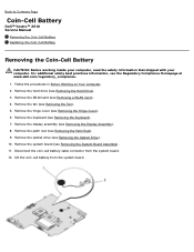
... from the system board. 12. Disconnect the coin-cell battery cable connector from the system board. Remove the fan (see Removing the Palm Rest). 9. Back to Contents Page Coin-Cell Battery Dell™ Vostro™ 2510 Service Manual Removing the Coin-Cell Battery Replacing the Coin-Cell Battery Removing the Coin-Cell Battery CAUTION...
... from the system board. 12. Disconnect the coin-cell battery cable connector from the system board. Remove the fan (see Removing the Palm Rest). 9. Back to Contents Page Coin-Cell Battery Dell™ Vostro™ 2510 Service Manual Removing the Coin-Cell Battery Replacing the Coin-Cell Battery Removing the Coin-Cell Battery CAUTION...
Service Manual
Page 70
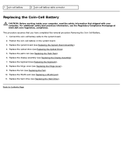
Replace the display assembly (see Replacing the Fan). 10. Replace the fan (see Replacing the Display Assembly). 7. Replace the WLAN card (see Replacing the Optical Drive). 5. This procedure assumes that shipped with your computer, read ... WLAN Card). 11. For additional safety best practices information, see Replacing the Palm Rest). 6. Replace the palm rest (see the Regulatory Compliance Homepage at www.dell.com/regulatory_compliance. Replace the hinge cover (see Replacing the Hard Drive). Replace the hard drive (see Replacing the Hinge Cover). 9. 1 coin-cell battery 2 coin...
Replace the display assembly (see Replacing the Fan). 10. Replace the fan (see Replacing the Display Assembly). 7. Replace the WLAN card (see Replacing the Optical Drive). 5. This procedure assumes that shipped with your computer, read ... WLAN Card). 11. For additional safety best practices information, see Replacing the Palm Rest). 6. Replace the palm rest (see the Regulatory Compliance Homepage at www.dell.com/regulatory_compliance. Replace the hinge cover (see Replacing the Hard Drive). Replace the hard drive (see Replacing the Hinge Cover). 9. 1 coin-cell battery 2 coin...


